Institute, Cambridge, UK ... Enhancing the Pronunciation of English Suprasegmental Features ...... Education-in-China-201011.pdf (Accessed 23 July 2013). ...... (1970) to empower the oppressed as well as to press for accountability and ...... http://
2014 MDX. 2014. MDX. ACCESSORIES. DESCRIPTION. BASE. COMMENTS.
ASK YOUR ACURA DEALER ABOUT COLOUR/TRIM AND PRICING DETAILS.
14 mm / 20,8. M. Kompaktkerze. Z induktiver Widerstand. 4. C. 10 mm / 16,0. U.
Gleitfunkentyp oder. 5. D. 12 mm / 18,0. Zusatzfunkenstrecke. 6. E. 8 mm / 13,0. 7.
This Delhi Schedule of Rates (E & M) 2014 is prepared for the use of CPWD.
However, this ... revision and finalisation of Delhi Schedule of Rates (E&M) 2014.
durango 29. 16. MtB 650 .... Brand new for 2014: meet the durango 29 comp and
sport. these ..... crankset, sraM xg1195 10-42 cassette, avid xo trail 4-piston with
180mm ..... by nearly 4% compared to last year's fork with leading caliper brake.
Effects of diffusion drying schedules on gas and liquid permeability in ... Efectos de los programas de secado de difusión sobre la permeabilidad del gas.
accused this â'new class'â of wanting to transfer power from the free market to the ... agenda, the right-believing Christians must vanquish all others as heathens or ..... 31 Charles P. Pierce, âGreetings from Idiot America,â Esquire Magazin
May 7, 2015 - country's largest listed containerized cargo services company with 22 vessels or a total of 202k DWT ... C
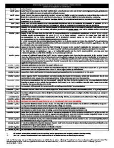
Mar 3, 2014 ... Those actions indicating “Procedures” are from the document, Procedures for
End ... FEC Secretary will review procedures and sample memos.
Feb 15, 2012 ... Lieutenant Colonel Jack C. Chambers ..... According to the 2010 U. S. Census .....
The crash involved a Honda Accord and a Ford F-550 truck. ... the runaways in
the snow to the point where they crossed the Black Water River.
DoUblE DIN INGENIX GPS NavIGatIoN SoUrCE UNIt W/ 7” lCD toUCH SCrEEN
... OEM Upgrade Systems Include: ... F-84SNTA11 '11 HyUNDAI SONATA.
Dec 10, 2014 ... Die volgende resepte bevat almal roosmaryn, dis maklik om in jou eie tuin te ......
en hanteringsfooi) en ons stuur elke maand vir jou 'n GRATIS.
Rabia Bozdogan Arpaci, Murat Bozlu. Large impacted bladder calculus ... Orcun Celik, Tumay Ipekci, Hatem Kazimoglu,. Gonca Unlu. Investigation of the ...
Teaching pronunciation: A handbook for teachers and trainers. New South Wales: ..... students for external exams, like Cambridge, IELTS or LCCI exams. .... downloaded free of charge in pdf format from the ECML website, the. RESOURCES ...
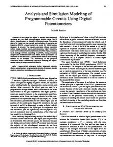
active building blocks for programmable analog circuits and devices. ... and the principles of operation of the RDAC potentiometers are described in section II; ...
6. I . As second measure of similarity, the linear correlation factor was applied k r , counted according to the following formula [Krysicki, Włodarski, 1983]:.
Those actions indicating “Procedures” are from the document, Procedures for
End of First ... FEC Secretary will review procedures and sample memos. JCRs
will ...
DIRECCIÓN GENERAL DE ORDENACIÓN DE LA SEGURIDAD SOCIAL.
INFORME ..... 97. 1.1.1. Cotización total Régimen General para el año 2014.
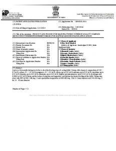
1369/KOL/2014. (19) INDIA. (22) Date of filing of Application :31/12/2014. (43) Publication Date : 22/07/2016. аааааааJournal No.ана30/2016. (54) Title of the ...
May 7, 2015 - Tirtamas Express. Jakarta. Shipping. 2000. Anemi Maritime Co. Ltd ..... TRANSPORT CORP OF INDIA LTD ... Au
Cool Passion: Challenging. Higher Education. ..... Build Your Own Website: A Comic Guide to HTML,. CSS, and WordPress. C
Those actions indicating “Procedures” are from the document, Procedures for
End of First ... FEC Secretary will review procedures and sample memos. JCRs
will ...
May 18, 2014 - Dr. Mustafa PEHLÄ°VAN (Dean, EreÄli Faculty of Education). Assoc. Prof. ... Assoc.Prof.Dr. Pasha ANTONENKO â O. S. U., U.S.A.. Prof.Dr. Paul ...
CONDENSED TABLE OF CONTENTS PREFACE ix ACKNOLEDGEMENTS
x
PART I BASIC DEVICES AND ANALOG CIRCUITS 1 2 3 4
Semiconductors theory and diodes 1 Bipolar Junction Transistor 29 Field Effect Transistors 67 Operational Amplifiers 93
PART II DIGITAL CIRCUITS 5 6 7
Logic 141 Binary Systems Data converters
APPENDIXES 1 2 3 4 5 6 7 8 9 10
1
174 187
207
Internal source resistance 208 Passive elements 209 Bipolar power supply 218 Superposition theorem 222 Capacitance 228 Inductance 234 Resonant circuit 238 Power transfer 243 Euler formula 246 Sine wave voltage measurement
REFERENCES
140
247
249
iii
DETAILED TABLE OF CONTENTS PREFACE ix ACKNOLEDGEMENTS
PART I
x
BASIC DEVICES AND ANALOG CIRCUITS
1 Semiconductor theory and diodes 1.1 Semiconductor elements 1.1A 1.1B
2
3
Doping elements 3 Electronic diode structure
5
1.2 The diode 6 1.2A 1.2B 1.2C 1.2D
I-V characteristics 7 Thermal characteristics Ideal diode 9 Piecewise linear model
Single phase rectifier bridge (Greatz bridge) Three phase rectifier bridge 19 Voltage multiplier 20 Final note on diodes 22
2.1 The BJT structure
Problems
iv
29
30
Configuration and operation 31 Transfer Characteristics 35 DC load line 37 DC circuit approximation 40 AC circuit approximation 41 Base-emitter resistance approximation Trans-conductance 44 Breakdown voltage limits 45
Low pass filter High pass filter Band pass filter Band stop filter
118 120 122 123
124
DIGITAL CIRCUITS
129
130 Introduction 131 Logic families 131 Symbols related to logic states 133 Activity level symbols 134 Logic level and signal information 134 Logic gates 136 5.6A 5.6B 5.6C 5.6D 5.6E 5.6F
5.7 Buffers 5.7A 5.7B 5.7C 5.7D 5.7E 5.7F 5.7G
5.8 Counters 5.9 Flip flops 5.9A 5.9B 5.9 C
5.10 Timers
AND 136 NAND 136 OR 138 NOR 138 XOR 138 XNOR 139
139 Inverter buffer 139 Positive gate enable three state buffer 139 Negative gate enable three state buffer 140 Three state buffer circuit 140 Three state buffer in high impedance mode Z 142 Three state buffer in low output mode L 143 Three state buffer in high output mode H 144
145 147 SR D JK
147 148 149
150
5.10A 74121 timer 150 5.10B 555 timer 151 5.10B1 555 in astable mode 151 5.10B2 555 in monostable mode 154
5.11 Multiplexers 5.11A 5.11B
Problems
vi
154
Digital multiplexer 154 Analog multiplexer 155
156
6
Binary Systems 6.1 6.2 6.3 6.4 6.5 6.6 6.7 6.8
7
161
Introduction 162 Base 2 system 162 Binary code generation 163 Binary operations 165 Decimal to binary conversion 168 Hexadecimal system 169 Decimal to hexadecimal conversion 171 Grey code generation 171 Problems 172
Data converters
175
7.1 Introduction 176 7.2 Digital to analog converter 7.2A 7.2B
R2R ladder circuit Multiplying DAC
7.3 Analog to digital converters 7.3A 7.3B 7.3C 7.3D 7.3E 7.3F
7.6B
7.6C
7.6D
Problems
184
188
192 193
Resolution 193 Absolute accuracy 193 Relative accuracy 194 Linearity 194 Conversion time 194 Slew rate and settling time
7.4 Sample track hold amplifiers 7.5 Data converter specifications 7.5A 7.5B 7.5C 7.5D 7.5E 7.5F
176
195
195
Fabrication process errors 195 7.6A1 Non-linearity 196 7.6A2 Non-monotonicity 196 7.6A3 Missing codes 197 7.6A4 Differential linearity 197 7.6A5 Offset error 198 7.6A6 Gain error 198 7.6A7 Glitches 199 Temperature and supply errors 200 7.6B1 Drift error 200 7.6B2 Long term drift 200 7.6B3 Supply sensitivity 201 Time errors 201 7.6C1 Aperture error 201 7.6C2 Aperture error minimization Quantizing error 202
202
203
vii
APPENDIXES 1 2 3 4 5 6 7 8 9 10
REFERENCES
viii
207
Internal source resistance 208 Passive elements 209 Bipolar power supply 218 Superposition theorem 222 Capacitance 228 Inductance 234 Resonant circuit 238 Power transfer 243 Euler formula 246 Sine wave voltage measurement
249
247
PREFACE Just few years ago senior physicists expressed a need for a comprehensive approach to electronic basic theory. This new perspective involved a complete redesign of the course given at that time and efforts were made to reach that goal. Therefore finding an appropriate topic selection forming a balanced synthesis between theory and practice became a twofold project mainly dedicated to medical physics students at master’s level. This book contains the following topics. -
Chapter 1 reviews the physics of semiconductor materials and diodes.
-
Chapter 2 is dedicated to bipolar junction transistors.
-
Chapter 3 covers field effect transistors up to the MESFETs.
-
Chapter 4 deals with operational amplifiers and their applications.
-
Chapter 5 covers logic components such as gates, counters, flip-flops multiplexers and timers.
-
Chapter 6 reviews binary and hexadecimal systems.
-
Chapter 7 covers digital to analog converters DAC’s and analog to digital converters ADC’s.
Since quantum theory led to the discovery of the bipolar transistor, nothing has changed regarding their basic properties. But after more than half a century of improvements new versions have emerged like FET, MOSFET and others as well. Therefore the field of transistor application grew almost exponentially. The early 5 mm size transistor has ended the use of heavy radio vacuum tubes. The modern fabrication processes shrunk the transistor down to microscopic scale. The hardware industry built its success on that very basic component by packing millions of them in small plastic packages, called integrated circuits. They run the most powerful computers, high-speed Internet networks and satellite communications as well. This book is dedicated to those in need to review the fundamentals electronic principles of and their use.
ix
ACKNOWLEDGEMENTS Personally encouraged to do this work by Dr. Ervin Podgorsak, as the Director of the Medical Physics Unit of the McGill University Health Center he provided me tools to put together this material. I must also thank him for his precious tips and advice regarding the presentation of the material. Writing such a document took time and efforts in reaching its first publication in 2005. Since then this document went through a series of revisions and updates. Thanks to many students for their suggestions and help from many colleagues. I would also like to thank our Medical Physics secretary Ms. Margery Knewstubb, for her kind help in revising my text and her recommendations on many occasions.