Widespread use of computer networks and the use of varied technology for the interconnection ... A congestion control scheme helps the network to recover from.
Congestion Avoidance in Computer Networks With a Connectionless Network Layer Raj Jain, K. K. Ramakrishnan, Dah-Ming Chiu Digital Equipment Corporation 550 King St. (LKG1-2/A19) Littleton, MA 01460 DEC-TR-506 c 1988, Digital Equipment Corporation. All rights reserved. Copyright Version:June 1, 1997
Abstract
Widespread use of computer networks and the use of varied technology for the interconnection of computers has made congestion a signi cant problem. In this report, we summarize our research on congestion avoidance. We compare the concept of congestion avoidance with that of congestion control. Brie y, congestion control is a recovery mechanism, while congestion avoidance is a prevention mechanism. A congestion control scheme helps the network to recover from the congestion state while a congestion avoidance scheme allows a network to operate in the region of low delay and high throughput with minimal queuing, thereby preventing it from entering the congested state in which packets are lost due to bu�er shortage. A number of possible alternatives for congestion avoidance were identi ed. From these alternatives we selected one called the binary feedback scheme in which the network uses a single bit in the network layer header to feed back the congestion information to its users, which then increase or decrease their load to make optimal use of the resources. The concept of global optimality in a distributed system is de ned in terms of e�ciency and fairness such that they can be independently quanti ed and apply to any number of resources and users. The proposed scheme has been simulated and shown to be globally e�cient, fair, responsive, convergent, robust, distributed, and con guration-independent.
1 INTRODUCTION
queuing and congestion. We are concerned here with congestion avoidance rather than congestion control. Brie y, a congestion avoidance scheme allows a network to operate in the region of low delay and high throughput. These schemes prevent a network from entering the congested state in which the packets are lost. We will elaborate on this point in the next section where the terms ow control, congestion control, and congestion avoidance will be de ned and their relationship to each other discussed. We studied a number of alternative schemes for congestion avoidance. Based on a number of requirements described later in this report, we selected an
Congestion in computer networks is becoming a signi cant problem due to increasing use of the networks, as well as due to increasing mismatch in link speeds caused by intermixing of old and new technology. Recent technological advances such as local area networks (LANs) and ber optic LANs have resulted in a signi cant increase in the bandwidths of computer network links. However, these new technologies must coexist with the old low bandwidth media such as the twisted pair. This heterogeneity has resulted in mismatch of arrival and service rates in the intermediate nodes in the network, causing increased 1
performance. A ow control scheme protects the destination from being ooded by the source. Some of the alternatives that have been described in the literature are window ow-control, Xon/Xo� [7], rate ow-control [5], etc. In the window owcontrol scheme, the destination speci es a limit on the number of packets that the source may send without further permission from the destination. Let us now extend the con guration to include a communication subnet (see Figure 1b) consisting of routers and links that have limited memory, bandwidth, and processing speeds. Now the source must not only obey the directives from the destination, but also from all the routers and links in the network. Without this additional control the source may send packets at a rate too fast for the network, leading to queuing, bu�er over ow, packet losses, retransmissions, and performance degradation. A congestion control scheme protects the network from being
ooded by its users (transport entities at source and destination nodes). In connection-oriented networks the congestion problem is generally solved by reserving the resources at all routers during connection setup. In connectionless networks it can be done by explicit messages (choke packets) from the network to the sources [19], or by implicit means such as timeout on a packet loss. In [15, 13, 21], a number of alternatives have been discussed and a timeout-based scheme has been analyzed in detail. Traditional congestion control schemes help improve the performance after congestion has occurred. Figure 2 shows general patterns of response time and throughput of a network as the network load increases. If the load is small, throughput generally keeps up with the load. As the load increases, throughput increases. After the load reaches the network capacity, throughput stops increasing. If the load is increased any further, the queues start building, potentially resulting in packets being dropped. Throughput may suddenly drop when the load increases beyond this point and the network is said to be congested. The response-time curve follows a similar pattern. At rst the response time increases little with load. When the queues start building up, the response time increases linearly until nally, as the
alternative called the binary feedback scheme for detailed study. This scheme uses only a single bit in the network layer header to feed back the congestion information from the network to users, which then increase or decrease their load on the network to make e�cient and fair use of the resources. We present precise de nitions of e�ciency and fairness that can be used for other distributed systems as well. This report is a summary of our work in the area of congestion avoidance in connectionless networks. We have tried to make this summary as self-contained and brief as possible. For further information, the reader is encouraged to read detailed reports in [16, 22, 4, 23].
2 CONCEPTS In this section we de ne the basic concepts of ow control, congestion control, and congestion avoidance.
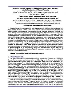
Figure 1: Consider the simple con guration shown in Figure 1a, in which two nodes are directly connected via a link. Without any control, the source may send packets at a rate too fast for the destination. This may cause bu�er over ow at the destination, leading to packet losses, retransmissions, and degraded 2
A scheme that allows the network to operate at the knee is called a congestion avoidance scheme, as distinguished from a congestion control scheme that tries to keep the network operating in the zone to the left of the cli�. A properly designed congestion avoidance scheme will ensure that the users are encouraged to increase their tra�c load as long as this does not signi cantly a�ect the response time and are required to decrease them if that happens. Thus, the network load oscillates around the knee. Congestion control schemes are still required, however, to protect the network should it reach the cli� due to transient changes in the network. The distinction between congestion control and congestion avoidance is similar to that between deadlock recovery and deadlock avoidance. Congestion control procedures are curative and the avoidance procedures are preventive in nature. The point at which a congestion control scheme is called upon depends upon the amount of memory available in the routers, whereas the point at which a congestion avoidance scheme is invoked is independent of the memory size. We elaborate further on these concepts in [16].
3 ALTERNATIVES
Figure 2:
Congestion control and congestion avoidance are dynamic system control issues. Like all other control schemes they consist of two parts: a feedback mechanism and a control mechanism. The feedback mechanism allows the system (network) to inform its users (sources or destinations) of the current state of the system, and the control mechanism allows the users to adjust their loads on the system. The problem of congestion control has been discussed extensively in the literature. A number of feedback mechanisms have been proposed. If we extend those mechanisms to operate the network around the knee rather than the cli�, we obtain congestion avoidance mechanisms. For the feedback mechanisms we have the following alternatives:
queues start over owing, the response time increases drastically. The point at which throughput approaches zero is called the point of congestion collapse. This is also the point at which the response time approaches in nity. The purpose of a congestion control scheme (such as [15, 3]) is to detect the fact that the network has reached the point of congestion collapse resulting in packet losses, and to reduce the load so that the network returns to an uncongested state. We call the point of congestion collapse a cli� due the fact that the throughput falls o� rapidly after this point. We use the term knee to describe the point after which the increase in the throughput is small, but after which a signi cant increase in the response time results.
1. Congestion feedback via packets sent from routers to sources 3
2. Feedback included in the routing messages ex- the destination either asks the source to reduce the changed among routers load or returns the signal back to the source in the packets (or acknowledgments) going in the reverse 3. End-to-end probe packets sent by sources direction. This is the alternative that we study here 4. Each packet containing a congestion feedback and in [22, 23]. eld lled in by routers in packets going in the The key architectural assumption about the networks in this study is that they use connectionless reverse direction{ reverse feedback network service and transport level connections. By 5. Each packet containing a congestion feedback this we mean that a router is not aware of the trans eld lled in by routers in packets going in the port connections passing through it, and the transport entities are not aware of the path used by their forward direction{ forward feedback packets. There is no prior reservation of resources The rst alternative is popularly known as choke at routers before an entity sets up a connection. The packet [19] or source quench message in ARPAnet routers cannot compute the resource demands except [20]. It requires introducing additional tra�c in the by observing the tra�c owing through them. Exnetwork during congestion, which may not be desir- amples of network architectures with connectionless able. network layers are DoD TCP/IP, DNA, and ISO conThe second alternative, increasing the cost (used nectionless network service used with ISO transport in updating the forwarding database) of congested class 4 [9]. paths, has been tried before in ARPAnet's delaysensitive routing. The delays were found to vary too quickly, resulting in a high overhead [18]. The third alternative, probe packets, also su�ers from the disadvantage of added overhead, unless probe packets have a dual role of carrying other information in them. If the latter were the case, there A congestion avoidance scheme is basically a resource would be no reason not to use every packet going allocation mechanism in which the subnet (set of inthrough the network as a probe packet. We may termediate nodes or routers) is a set of m resources achieve this by reserving a eld in the packet that that has to be allocated to n users (source-destination is used by the network to signal congestion. This pairs). There are two parties involved in any resource allocation mechanism: the resource manager and the leads us to the last two alternatives. The fourth alternative, reverse feedback, requires user. The resource manager's goal is to use the rerouters to piggyback the signal on the packets going source as e�ciently as possible. Users, on the other in the direction opposite the congestion. This alter- hand, are more interested in getting a fair share of native has the advantage that the feedback reaches the resource. We therefore need to de ne e�ciency the source faster. However, the forward and reverse and fairness. tra�c are not always related. The destinations of the For our current problem of congestion avoidance, reverse tra�c may not be the cause of or even the par- the routers are our resources and therefore we use ticipants in the congestion on the forward path. Also, the terms routers and resources interchangeably. The many networks (including Digital Network Architec- concepts introduced here, however, are general and ture, or DNA) have path-splitting such that the path apply to other distributed resource allocation probfrom A to B is not necessarily the same as that from lems as well. Similarly, for the current problem, the demands and allocations are measured by packB to A. The fth alternative, forward feedback, sends the ets/second (throughput), but the concepts apply to signal in the packets going in the forward direction other ways of quantifying demands and allocations. (direction of congestion). In the case of congestion Readers not interested in de nitions of these met-
4 PERFORMANCE RICS
4
MET-
rics may skip to the next section on the proposed the total throughput is equal to the knee-capacity of scheme. the resource. However, a maximally e�cient allocation may not be fair, as some users may get better treatment than others. The fairness of an allocation 4.1 Single Resource, Single User is a function of the amounts demanded as well as the Consider rst only one user and one resource. In this amounts allocated. To simplify the problem, let us case fairness is not an issue. If the user is allowed rst consider the case of equal demands in which all to increase its demand (window), the throughput in- users have identical demands (D). The maximally creases. However, the response time (total waiting fair allocation then consists of equal allocations to time at the resource) also increases. Although we all users, i.e., ai = A for all i. The fairness of any want to achieve as high a throughput as possible, we other (non-equal) allocation is measured by the folalso want to keep the response time as small as possi- lowing fairness function [11]: ble. One way to achieve a tradeo� between these conP ( Pni=1 xi )2
icting requirements is to maximize resource power Fairness = (1) n 2 [8, 17], which is de ned by:
n i=1 xi
Resource Throughput� Resource Power = Resource Response Time
where xi = ai =D. This function has the property that its value always lies between 0 and 1 and that 1 (or 100%) represents a maximally fair allocation. Notice that we use user throughput to measure allocations and demands because of its additivity property: total throughput of n users at a single resource is the sum of their individual throughputs.
Here, � is a constant. Generally, � = 1. Other values of � can be used to give higher preference to throughput (� > 1) or response time (� < 1). The concepts presented in this report apply to any value of �. However, unless otherwise speci ed we will assume throughout this report that � = 1. The resource power is maximum at the knee. For any given inter-arrival and service time distributions, we can compute the throughput at the knee. We call this the knee-capacity of the resource. The maximally e�cient operating point for the resource is its knee. The e�ciency of resource usage is therefore quanti ed by: Resource Power Resource E�ciency = Resource Power at Knee The resource is used at 100% e�ciency at the knee. As we move away from the knee, the resource is being used ine�ciently, that is, either underutilized (throughput lower than the knee-capacity) or overutilized (high response time).
4.3 Single Resource, Multiple Users with Unequal Demands
Given a resource with knee-capacity of Tknee , each of the n users deserves a fair share of Tknee =n. However, there is no point in allocating Tknee =n to a user who is demanding less than Tknee =n. It would be better to give the excess to another user who needs more. This argument leads us to extend the concept of maximally fair allocation such that the fair share tf is computed subject to the following two constraints: 1. The resource is fully allocated:
Xn a = T i=1
4.2 Single Resource, Multiple Users with Equal Demands
i
knee
2. No one gets more than the fair share or its demands ai = minfdi ; tf g
With multiple users we have an additional requirement of fairness. The allocation is e�cient as long as 5
4.5 Multiple Resources, Users
Given the knee capacity of a resource and individual user demands, the above two constraints allows us to determine the maximally fair allocation fA�1 ; A�2 ; : : : ; A�n g. If actual allocation fa1 ; : : : ; an g is di�erent from this, we need a distance function to quantify the fairness. We do this by using the fairness function of equation 1 with xi = ai =A�i . The e�ciency of the resource usage can be computed as before by computing resource power from the resource throughput (which is given as the sum of user throughputs in this case) and the resource response time. The allocation that is 100% e�cient and 100% fair is the optimal allocation. We must point out that the above discussion for a single resource case also applies if there are multiple (m) routers but all routers are shared by all n users. In this case the set of m routers can be combined and considered as one resource.
Multiple
In this case, there are n users and m resources. The ith user has a path pi consisting of a subset of resources fri1 ; ri2 ; : : : ; rim g. Similarly, j th resource serves nj users fUj1 ; Uj2 ; : : : ; Ujn g. The global e�ciency is still de ned by the bottleneck resource which is identi ed by the resource with the highest utilization. The problem of nding the maximally e�cient and maximally fair allocation is now a constrained optimization problem as it has to take di�ering user paths into account. We have developed an algorithm [23] which gives the globally optimal (fair and e�cient) allocation for any given set of resources, users, and paths. Once globally optimal allocation fA�1 ; A�2 ; : : : ; A�n g has been determined, it is easy to quantify fairness of any other allocation fa1; a2 ; : : : ; an g by using the same fairness function as in the single resource case (equation 1) with xi = ai =A�i . This fairness is called global fairness and the e�ciency of the bottleneck resources is called the global e�ciency. An allocation which is 100% globally ef cient and 100% globally fair is said to be globally optimal. It should be pointed out that by associating e�ciency with resource power (rather than user power), we have been able to avoid the problems encountered by other researchers [2, 10] in using the power metric. Notice that we have a multi-criteria optimization problem since we are trying to maximize e�ciency as well as fairness. One way to solve such problems is to combine the multiple criteria into one, for instance by taking a weighted sum or by taking a product. We chose instead to put a strict priority on the two criteria. E�ciency has a higher priority than fairness. Given two alternatives, we prefer the more e�cient alternative. Given two alternatives with equal e�ciency, we choose the fairer alternative. i
j
4.4 Multiple Resources, One User
We have extended the concepts of fairness and ef ciency to a distributed system with multiple resources. Let us rst consider a case of a single user so that fairness is not an issue. For the subnet congestion problem, the user has a path P passing through m resources (routers) fr1 ; r2 ; : : : ; rm g. The resource with the lowest service rate determines the user's throughput and is called the bottleneck resource. The bottleneck resource has the highest utilization (ratio of throughput to service rate) and contributes the most to user's response time. The maximally e�cient operating point for the system is de ned as the same as that for the bottleneck router. Thus, given a system of m resources, we determine the bottleneck and de ne its e�ciency as the global e�ciency and its knee as the maximally e�cient operating point for the system. Global E�ciency = E�ciency of the Bottleneck Resource
5 THE PROPOSED SCHEME
Note that the global e�ciency, as de ned here, depends upon the response time at the bottleneck resource and not on the user response time, which is a We have designed a scheme that allows a network to sum of response time at m resources. operate at its knee. As shown in Figure 3, the scheme 6
proach, while the ISO TP4 [9] implementation uses the destination-based approach. In the remainder of this report, we use the word user to include both source and destination transport entities. Thus, when we say that the user changes its window, the change might be decided and a�ected by the source or destination transport entity.
Figure 3: uses one bit called the congestion avoidance bit in the network layer header of the packet for feedback from the subnet to the users. A source clears the congestion avoidance bit as the packet enters the subnet. All routers in the subnet monitor their load and if they detect that they are operating above the knee, they set the congestion avoidance bit in the packets belonging to users causing overload. Routers operating below the knee pass the bit as received. When the packet is received at the destination the network layer passes the bit to the destination transport, which takes action based on the bits. There are two versions of the binary feedback scheme: 1. Destination-based 2. Source-based In the rst version, the destination examines the bits received, determines a new ow-control window, and sends this window to the source. In the second version, the destination sends all bits back to the source along with the acknowledgments. In this case, we need to reserve one bit in the headers of transport layer acknowledgment packets where the destination transport entity copies the bit received from the network layer. The source transport entity examines the stream of bits received, determines a new operating window, and uses it as long as it does not violate the window limit imposed by the the destination. We have studied both versions. The NSP transport protocol in DNA [6] uses the source-based ap-
Figure 4: The proposed congestion avoidance scheme consists of two parts: a feedback mechanism in routers, and a control mechanism for users. We call these the router policy and the user policy, respectively. Each of these mechanisms can be further subdivided into three components as shown in Figure 4. We explain these components below. For further details see [16, 22, 23].
5.1 Router Policies
Routers in a connectionless network environment are not informed about resource requirements of transport entities and therefore they have no prior knowledge of future tra�c. They attempt to optimize their operation by monitoring the current load and by asking the users (via the bit) to increase or decrease the load. Thus, the routers have three distinct algorithms: 1. To determine the instantaneous load level 7
2. To estimate average load over a appropriate time queue lengths over a long interval. The key question interval is how long an interval is long enough. 3. To determine the set of users who should be asked to adjust their loads We call these three algorithms congestion detection, feedback lter, and feedback selections, respectively. The operation of these components and the alternatives considered are described next.
5.1.1 Congestion Detection
Before a router can feed back any information, it must determine its load level. It may be underutilized (below the knee) or overutilized (above the knee). This can be determined, based on the utilization, bu�er availability, or queue lengths. We found that the average queue length provides the best mechanism to determine if we are above or below the knee. This alternative is least sensitive to the arrival or service distributions and is independent of the memory available at the router. For both M/M/1 and D/D/1 queues the knee occurs when the average queue length is one. For other arrival patterns such as packet trains [14], this is approximately (though not exactly) true. The routers, therefore, monitor the queue lengths and ask users to reduce the load if the average queue length is more than one, and vice versa.
Figure 5: We recommend averaging since the beginning of the previous regeneration cycle. A regeneration cycle is de ned as the interval consisting of a busy period and an idle period, as shown in Figure 5. The beginning of the busy period is called a regeneration point. The word regeneration signi es the birth of a new system, since the queuing system's behavior after the regeneration point does not depend upon that before it. The average queue length is given by the area under the curve divided by the time since the last but one regeneration point. Note that the averaging includes a part of the current, though incomplete, cycle. This is shown in Figure 5.
5.1.2 Feedback Filter
5.1.3 Feedback Selection
After a router has determined its load level, its feedback to users is useful if and only if the state last long enough for the users to take action based on it. A state that changes very fast may lead to confusion because by the time users become aware of it, the state no longer holds and the feedback is misleading. Therefore, we need a low-pass lter function to pass only those states that are expected to last long enough for the user action to be meaningful. This consideration rules out the use of instantaneous queue lengths to be used in congestion detection. An instantaneous queue length of 100 may not be a problem for a very fast router but may be a problem for a slow router. We need to average the
The two components of router policy discussed so far (congestion detection and feedback lter) ensure that the router operates e�ciently, that is, around the knee. They both work based upon the total load on the router, to decide if the total load is above the knee or below the knee. The total number of users or the fact that only a few of the users might be causing the overload is not considered in those components. Fairness considerations demand that only those users who are sending more than their fair share should be asked to reduce their load, and others should be asked to increase if possible. This is done by the feedback selection, an important component of our 8
5.2.1 Signal Filter
scheme. Without the selection, the system may stabilize at (operate around) an operating point that is e�cient but not fair. For example, two users sharing the same path may keep operating at widely di�erent throughputs. The feedback selection works by keeping a count of the number of packets sent by di�erent users since the beginning of the queue averaging interval. This is equivalent to monitoring their throughputs. Based on the total throughput, a fair share is determined and users sending more than the fair share are asked to reduce their load while the users sending less than the fair share are asked to increase their load. Of course, if the router is operating below the knee, each one is encouraged to increase regardless of their current load. The fair share is estimated by assuming the capacity to be at 90% of the total throughput since the beginning of the last regeneration cycle. The feedback selection as proposed here attempts to achieve fairness among di�erent network layer service access point (NSAP) pairs because the packet counts used in the algorithm correspond to these pairs. This completes the discussion on the router policies. We now turn to the user policies.
The problem solved by this component is to examine the stream of the last n bits, for instance, and to decide whether the user should increase or decrease its load (window). Mathematically,
d = f (b1 ; b2 ; b3; : : : ; bn ) Here, d is the binary decision (0 ) increase, 1 ) decrease) and bi is the the ith bit with bn being the most recently received bit. The function f is the signal lter function. The function that we nally chose requires counting the number of 1s and 0s in the stream of the last n bits. Let
s1 = number of ones in the stream =
Xb
i
s0 = number of zeros in the stream = n , s1 Then, if s1 > pn then d = 1 else d = 0. Here, p is
a parameter called cuto� probability. We found that for exponentially distributed service times, the optimal choice was p = 0:5, as expected. For deterministic service times, however, we found that the choice of p does not matter. This is because in deterministic cases, the router ltering results in the user consistently receiving either all 1s if the load at the bottleneck is above the knee or all 0s if the load is below the knee. Based on this observation, we recommend using a cuto� probability of 50%. In summary, the signal ltering simply consists of comparing the counts of 1s and 0s received in the bit stream and deciding to go up or down as indicated by the majority of the bits.
5.2 User Policies
Each user receives a stream of congestion avoidance bits, called signals, from the network. These signals are not all identical (or else we would not need all of them). Some signals ask the user to reduce the load, while others ask it to increase the load. The user policy should be designed to compress this stream into a single increase/decrease decision at suitable intervals. The key questions that the user policy helps answer are: 1. How can all signals received be combined?
5.2.2 Decision Frequency
The decision frequency component of the user policy consists of deciding how often to change the window. Changing it too often leads to unnecessary oscillations, whereas changing it infrequently leads to a 2. How often should the window be changed? system that takes too long to adapt. System control theory tells us that the optimal 3. How much should the change be? control frequency depends upon the feedback delay We call these three algorithms signal lter, deci- { the time between applying a control (change winsion frequency, and increase/decrease algorithm, re- dow) and getting feedback (bits) from the network spectively. corresponding to this control. 9
In computer networks, it takes one round-trip delay to a�ect the control, that is, for the new window to take e�ect and another round-trip delay to get the resulting change fed back from the network to the users. This leads us to the recommendation that windows should be adjusted once every two round-trip delays (two window turns) and that only the feedback signals received in the past cycle should be used in window adjustment, as shown in Figure 6.
new information available since the last activation of the component. We therefore chose the simple approach. We have already partitioned the problem so that the signal lter looks at the feedback signals and decides whether to increase or decrease. The increase/decrease algorithm, therefore, needs to look at the window in the last cycle and decide what the new window should be. We limited our search among alternatives to the rst order linear functions for both increase and decrease: Increase: wnew = awold + b Decrease: wnew = cwold , d Here, wold is the window in the last cycle and wnew is the window to be used in the next cycle; a, b, c, and d are non-negative parameters. There are four special cases of the increase/decrease algorithms:
a Multiplicative Increase, Additive Decrease (b = 0, c = 1)
b Multiplicative Increase, Multiplicative Decrease (b = 0, d = 0)
c Additive Increase, Additive Decrease (a = 1, c = 1)
d Additive Increase, Multiplicative Decrease (a = 1, d = 0)
Figure 6:
The choices of the alternatives and parameter values are governed by the following goals:
5.2.3 Increase/Decrease Algorithms The purpose of the increase/decrease algorithm is to determine the amount by which the window should be changed once a decision has been made to adjust it. In the most general case, the increase (or decrease) amount would be a function of the complete past history of controls (windows) and feedbacks (bits). In the simplest case, the increase/decrease amount would be a function only of the window used in the last cycle and the resulting feedback. Actually, there is little performance di�erence expected between the simplest and the most general control approach, provided that the simple scheme makes full use of the 10
1. E�ciency: The system bottleneck(s) should be operating at the knee. 2. Fairness: The users sharing a common bottleneck should get the same throughput. 3. Minimum Convergence Time: Starting from any state, the network should reach the optimal (ef cient as well as fair) state as soon as possible. 4. Minimum Oscillation Size: Once at the optimal state, the user windows oscillate continuously below and above this state. The parameters should be chosen such that the oscillation size is minimal.
These considerations lead us to the following recommendation for increase/decrease algorithms [16, 4]: Additive Increase: wnew = wnew + 1 Multiplicative Decrease: wnew = 0:875wold If the network is operating below the knee, all users go up equally, but, if the network is congested, the multiplicative decrease makes users with higher windows go down more than those with lower windows, making the allocation more fair. Note that 0:875 = 1 , 2,3 . Thus, the multiplication can be performed without oating point hardware, by simple logical shift instructions. The computations should be rounded to the nearest integer. Truncation, instead of rounding, results in lower fairness. This completes our discussion of the proposed binary feedback scheme. The key router and user policy algorithms are summarized in the appendix.
6 FEATURES SCHEME
OF
THE
The design of the binary feedback scheme was based on a number of goals that we had determined beforehand. Below, we show how the binary feedback scheme meets these goals. 1. No control during normal operation: The scheme does not cause any extra overhead during normal (underloaded) conditions.
proposed scheme dynamically adjusts its operation to the current optimal point. The users continuously monitor the network by changing the load slightly below and slightly above the optimal point and verify the current state by observing the feedback. 5. Minimum oscillation: The increase amount of 1 and decrease factor of 0.875 have been chosen to minimize the amplitude of oscillations in the window sizes. 6. Convergence: If the network con guration and workload remain stable, the scheme brings the network to a stable operating point. 7. Robustness: The scheme works under a noisy (random) environment. We have tested it for widely varying service-time distributions. 8. Low parameter sensitivity: While comparing various alternatives, we studied their sensitivity with respect to parameter values. If the performance of an alternative was found to be very sensitive to the setting of a parameter value, the alternative was discarded. 9. Information entropy: Information entropy relates to the use of feedback information. We want to get the maximum information across with the minimum amount of feedback. Given one bit of feedback, information theory tells us that the maximum information would be communicated if the bit was set 50% of the time.
2. No new packets during overload: The scheme 10. Dimensionless parameters: A parameter that has dimensions (length, mass, time) is generally does not require generation of new messages a function of network speed or con guration. A (e.g., source quench) during overload conditions. dimensionless parameter has wider applicability. Thus, for example, in choosing the increase al3. Distributed control: The scheme is distributed gorithm we preferred increasing the window by and works without any central observer. an absolute amount of k packets rather than by 4. Dynamism: Network con gurations and tra�c a rate of t packets/second. The optimal value of vary continuously. Nodes and links come up and the latter depends upon the link bandwidth. All down and the load placed on the network by parameters of the proposed scheme are dimenusers varies widely. The optimal operating point sionless, making it applicable to networks with is therefore a continuously moving target. The widely varying bandwidths. 11
11. Con guration independence: We have tested the scheme for many di�erent con gurations of widely varying lengths and speeds including those with and without satellite links. Most of the discussion in this and associated reports centers around window-based ow-control mechanisms. However, we must point out that this is not a requirement. The congestion avoidance algorithms and concepts can be easily modi ed for other forms of ow control such as rate-based ow control, in which the sources must send at a rate lower than a maximum rate (in packets/second or bytes/second) speci ed by the destination. In this case, the users would adjust rates based on the signals received from the network.
7 COMPARISON WITH SIMILAR SCHEMES It must be pointed out that the binary feedback scheme proposed here is di�erent from most other schemes in that it is the rst attempt to achieve congestion avoidance rather than congestion control. Similar congestion control schemes exist in literature. For example, the congestion control scheme used in SNA [1] also uses bits in the network layer headers to feed back congestion information from the network to the source. It uses two bits called the change window indicator (CWI) and the reset window indicator (RWI). The rst bit indicates moderate congestion, while the second one indicates severe congestion. The CWI bit is set by a router when it nds that more than a percentage, such as 75%, of its bu�ers have been used. After all bu�ers are used up, the router starts setting RWI bits in the packets going in the reverse direction. On receipt of a CWI, the source decreases the window by 1. On the receipt of a RWI, the source resets the window to h, where h is the number of hops. If both bits are clear, the window is increased by one until a maximum of 3h is reached. The key di�erence between SNA's scheme (and all prior work in congestion control) and our binary feedback scheme is the de nition of the goal. SNA's goal is to ensure that packets nd bu�ers when they ar-
rive at the routers. Our scheme, on the other hand, is not so much concerned with the bu�ers. Rather it tries to maximize the throughput while also minimizing the delay. The routers start setting the bits as soon as the average queue length is more than one. The number of bu�ers available at the router has no e�ect on our scheme. The key test to decide whether a particular scheme is a congestion control or a congestion avoidance scheme is to consider a network with all nodes having in nite memory (in nite bu�ers). A congestion control scheme will generally remain inactive in such a network, allowing the users to use large windows causing high response time. A congestion avoidance scheme, on the other hand, is useful even in a network with in nite memory. It tries to adjust queuing in the network so that a high throughput and a low response time is achieved.
8 PERFORMANCE The binary feedback scheme was designed using a simulation model that allowed us to compare various alternatives and study them in detail. Most of the choices discussed earlier in this report have been justi ed using analytical arguments. However, we have veri ed all arguments using simulation as well. The model allows us to simulate any number of users going through various paths in the network. It is an extension of the model described in [12]. The model simulates portions of network and transport layers. The transport layer is modeled in detail. The routers are modeled as single server queues. The model's key limitation currently is that the acknowledgments returning from a destination to a source are not explicitly simulated. Instead, the source is informed of the packet delivery as soon as the packet is accepted by the destination. In this section, we present a few cases to illustrate the performance of the binary feedback scheme. Other simulation results including those for random service times and highly congested networks are given in [22, 23].
12
8.1 Case I (Single User)
and nding the window values that are e�cient and fair. The router 2 is the bottleneck. At the knee its throughput is 1/5 packets per unit time, divided equally between the two users. The optimal window in this case is w1 = 10 for user 1 and w2 = 5 for user 2. The plots of the two user's windows are shown in Figure 8b. Notice that with only one user the system stabilizes at the window of 15 and keeps oscillating around it until the second user joins the network. At this point, the rst user receives decrease signals from the bottleneck router while the second user receives increase signals. The windows eventually stabilize when they reach their optimal values. Figure 8c shows a plot of throughputs of the two users. The throughput of the rst user drops while that of the second increases until they both share the bottleneck approximately equally. Another feature of the scheme, which can be seen from this case, is that the scheme adapts as the number of users in the network changes. The users need not start at the same point (window of 1) to reach the fair operating point.
This case consists of a single user using a path consisting of four routers, as shown in Figure 7a. The service times at the routers are 2, 5, 3, and 4 units of time, respectively. In our simulation the user's speed is one packet per unit of time. In other words all times are expressed as multiples of time required to send one packet. The third router is a satellite link having a xed delay of 62.5 units of time. The second router is the bottleneck, and its power as a function of the window size is shown in Figure 7b. This graph is obtained by running the simulation without the binary feedback scheme at a xed window and observing the user throughput and response times. It is seen from this gure that the knee occurs at a window of 15.5. Figure 7c shows a plot of a user's window with the binary feedback scheme. The time is shown along the horizontal axis. Notice that the user starts with a window of 1 and sends packet 1 and 2; both packets traverse the subnet with the congestion bit clear. The user, therefore, increases the window to 2. Packets 3 and 4 are sent. After their acknowledgment, packets 5 and 6 are sent. The congestion bits in packets 5 and 6 are examined. They are clear and so the window is increased to 3. This continues until the window is 16. The key contributions of our congestion avoidance At this point, the bottleneck starts operating above research are the following: the knee and starts setting congestion bits in packets. The user, upon receiving these packets, reduces the 1. We have introduced the new term congestion avoidance. It has been distinguished from other window to 16(0.875) or 13. The cycle then repeats similar terms of ow control and congestion conand the window keeps oscillating between 13 and 16. trol. It has been shown that the preventive This case illustrates the fact that the network opmechanism, congestion avoidance, helps the neterates e�ciently. work use its resources in an optimal manner.
9 SUMMARY
8.2 Case II (Two Users)
To illustrate the fairness aspects of the scheme, consider the same con guration as in Case 1, except that we have now added another user that enters the subnet at router 1 and exits after router 2 (see Figure 8a). Also, the second user starts after the rst one has sent 200 packets. The optimal operating point for this case can be determined by running the simulation without the congestion avoidance scheme for various combinations of window sizes for the two users 13
2. We de ned the concept of global optimality in a distributed system with multiple resources and multiple users. The optimality is de ned by e�ciency and fairness. Both concepts have been developed so that they can be independently quanti ed and can apply to any number of resources and users. 3. Other researchers attempting to de ne global optimality have had di�culty extending the concept of power to distributed resources. By de n-
ing e�ciency for each resource and relating fairness to users, we have been able to separate the two concepts. 4. We have developed a simple scheme that allows a network to reach the optimal operating point automatically. This scheme makes use of a single bit in the network layer header. This bit is shared by all resources. 5. We divided the problem of congestion avoidance into six components which can be studied separately. This allowed us to compare a number of alternatives for each component and select the best. 6. We have simulated the binary feedback scheme and tested its performance in many di�erent con gurations and conditions. The scheme has been found to operate optimally in all cases tested.
10 ACKNOWLEDGMENTS Many architects and implementers of Digital's networking architecture participated in a series of meetings over the last three years in which the ideas presented here were discussed and improved. Almost all members of the architecture group contributed to the project in one way or another. In particular, we would like to thank Tony Lauck and Linda Wright for encouraging us to work in this area. Radia Perlman, Art Harvey, Kevin Miles, and Mike Shand are the responsible architects whose willingness to incorporate our ideas provided further encouragement. We would also like to thank Bill Hawe, Dave Oran, and John Harper for feedback and interest. The idea of proportional decrease was rst proposed by George Verghese and Tony Lauck. The concept of maximal fairness was developed by Bob Thomas and Cuneyt Ozveren.
References [1] V. Ahuja, \Routing and Flow Control in Systems Network Architecture," IBM Systems Journal, Vol. 18, No. 2, 1979, pp. 298 - 314.
[2] K. Bharat-Kumar and J. M. Ja�e, \A New Approach to Performance- Oriented Flow Control," IEEE Transactions on Communications, Vol. COM-29, No. 4, April 1981, pp. 427 - 435. [3] W. Bux and D. Grillo, \Flow Control in LocalArea Networks of Interconnected Token Rings," IEEE Transactions on Communications, Vol. COM-33, No. 10, October 1985, pp. 1058-66. [4] Dah-Ming Chiu and Raj Jain, \Analysis of Increase/Decrease Algorithms For Congestion Avoidance in Computer Networks," Digital Equipment Corporation, Technical Report TR509, August 1987, To be published in Computer Networks and ISDN Systems. [5] David Clark, \NETBLT: A Bulk Data Transfer Protocol," Massachusetts Institute of Technology, Lab for Computer Science, RFC-275, February 1985. [6] Digital Equipment Corp., \DECnet Digital Network Architecture NSP Functional Speci cation, Phase IV, Version 4.0.0," March 1982. [7] M. Gerla and L. Kleinrock, \Flow Control: A Comparative Survey," IEEE Transactions on Communications, Vol. COM-28, No. 4, April 1980, pp. 553 - 574. [8] A. Giessler, J. Haanle, A. Konig and E. Pade, \Free Bu�er Allocation - An Investigation by Simulation," Computer Networks, Vol. 1, No. 3, July 1978, pp. 191-204. [9] International Organization of Standardization, \ISO 8073: Information Processing Systems Open Systems Interconnection - Connection Oriented Transport Protocol Speci cation," July 1986. [10] J. M. Ja�e, \Flow Control Power is Nondecentralizable," IEEE Transaction on Communications, Vol. COM-29, No. 9, September 1981, pp. 1301-1306. [11] Raj Jain, Dah-Ming Chiu, and William Hawe, \A Quantitative Measure of Fairness
14
and Discrimination for Resource Allocation in Shared Systems," Digital Equipment Corporation, Technical Report TR-301, September 1984.
[20] [12] Raj Jain, \Using Simulation to Design a Computer Network Congestion Control Protocol," Proc. Sixteenth Annual Pittsburgh Conference [21] on Modeling and Simulation, Pittsburgh, PA, April 25-26, 1985, pp. 987-993. [13] Raj Jain, \Divergence of Timeout Algorithms for Packet Retransmission," Proc. Fifth Annual International Phoenix Conf. on Computers and [22] Communications, Scottsdale, AZ, March 26-28, 1986, pp. 174-179. [14] Raj Jain and Shawn Routhier, \Packet Trains - Measurements and a New Model for Computer Network Tra�c," IEEE Journal on Se- [23] lected Areas in Communications, Vol. SAC-4, No. 6, September 1986, pp. 986-995. [15] Raj Jain, \A Timeout-Based Congestion Control Scheme for Window Flow-Controlled Networks," IEEE Journal on Selected Areas in Communications, Vol. SAC-4, No. 7, October 1986, pp. 1162-1167. [16] Raj Jain and K. K. Ramakrishnan, \Congestion Avoidance in Computer Networks with a Connectionless Network Layer: Concepts, Goals and Methodology," Proc. IEEE Computer Networking Symposium, Washington, D. C., April 1988, pp. 134-143. [17] L. Kleinrock, \Power and Deterministic Rules of Thumb for Probabilistic Problems in Computer Communications," in Proc. Int. Conf. Commun., June 1979, pp. 43.1.1-10. [18] J. M. McQuillan, I. Richer, and E. C. Rosen, \The New Routing Algorithm for the ARPANET," IEEE Transactions on Communications, Vol. COM-28, No. 5, May 1980, pp. 711719. [19] J.C. Majithia, et al, \Experiments in Congestion Control Techniques," Proc. Int. Symp. Flow
Control Computer Networks, Versailles, France. February 1979. John Nagle, \Congestion Control in TCP/IP Internetworks," Computer Communication Review, Vol. 14, No. 4, October 1984, pp. 11-17. K. K. Ramakrishnan, \Analysis of a Dynamic Window Congestion Control Protocol in Heterogeneous Environments Including Satellite Links," Proceedings of Computer Networking Symposium, November 1986. K. K. Ramakrishnan and Raj Jain, \An Explicit Binary Feedback Scheme for Congestion Avoidance in Computer Networks with a Connectionless Network Layer," Proc. ACM SIGCOMM'88, Stanford, CA, August 1988. K. K. Ramakrishnan, Dah-Ming Chiu and Raj Jain, \Congestion Avoidance in Computer Networks with a Connectionless Network Layer. Part IV: A Selective Binary Feedback Scheme for General Topologies," Digital Equipment Corporation, Technical Report TR-510, August 1987.
Appendix A: Algorithms
The SIMULA procedures used in the simulation model are included here to clearly explain various algorithms used in the scheme. The data structures used by the queue servers in the routers are presented followed by ve procedures which are used as follows: 1. Arrival: This procedure is executed on each packet arrival. It computes the area under the queue length curve. Also, at the begining of a new cycle, the tables are initialized. SIMULA variable 'time' gives the currently simulated time. 2. Departure: This procedure is executed on the packet departure. It decreases the queue size and updates the value of area under the queue length curve. A hash function is used to nd the table entry where counts for packets sent by this user are kept. 3. Fair Share: This procedure is used to decide the maximum number of packets any user should be
15
allowed to send. The routers set the congestion avoidance bits in packets belonging to users sending more than this amount. 4. Increase: This procedure is used by a transport entity to increase its window if less than 50% of the bits received are set. 5. Decrease: This procedure is used by a transport entity to decrease its window if more than or equal to 50% of the bits are set. The SIMULA function Entier(x) returns the highest integer less than or equal to x. The rst two procedures are parts of the feedback lter algorithm discussed earlier under router policies. The third procedure constitutes the feedback selector algorithm. The last two procedures make up the increase/decrease algorithms of the user policies.
Figure 7:
16
Figure 8:
17
!The following data structure is maintained by each queue server or router. The size of the table 'dim_tables' to be used is left to the implementors; REAL ARRAY packets_sent[0:dim_tables];!Table for keeping packet counts; !0th location is used for total count; REAL ARRAY prev_packets_sent[0:dim_tables]; !Counts for previous cycle; REAL avg_q_length; !Average queue length at this server; REAL area; !Area under Q length vs time curve; REAL prev_area; !Area in the previous cycle; INTEGER q_length; !Queue length includes one in service; REAL q_change_time; !Last time the queue changed; REAL prev_cycle_begin_time; !Time at which previous cycle began; REAL cycle_begin_time; !Time at which this cycle began; PROCEDURE arrival; !To be executed on packet arrival; BEGIN INTEGER i; !Temporary index variable; area:=area+q_length*(time-q_change_time);!Compute Area under the curve; q_length:=q_length+1; !Increment number in the queue; q_change_time:=time; !Time of change in Queue length; IF(q_length=1) THEN !Begining of a new cycle; BEGIN !End the previous cycle; prev_cycle_begin_time:=cycle_begin_time; cycle_begin_time:=time; prev_area:=area; area:=0; FOR i:=0 STEP 1 UNTIL dim_tables DO BEGIN prev_packets_sent[i]:=packets_sent[i];!Remember all counts; packets_sent[i]:=0; !Clear packet counts; END; !of FOR; END; !of IF(Q_length=1); END of arrival; PROCEDURE departure; !To be executed on packet departure; BEGIN BOOLEAN bit; !The congestion avoidance bit in the packet; INTEGER user; !Index in the packet count table; area:=area+q_length*(time-q_change_time);!Compute area under the curve; q_length:=q_length-1; !Decrement the number in the queue; q_change_time:=time; !Rememeber time of queue length change; avg_q_length:=(area+prev_area)/(time-prev_cycle_begin_time);!Compute avg Q length; user:=hash(source_address,dest_address,dim_tables);!Find index into the table; packets_sent[user]:=packets_sent[user]+1;!Increment the count; packets_sent[0]:=packets_sent[0]+1;!Increment total count also; IF(avg_q_length>2) !Are we heavily congested?; THEN bit:=TRUE !Yes, set bit for all users;
18
ELSE IF (avg_q_lengthfair_share THEN bit:=TRUE; !If the user sent too many packets, set bit; END of departure;
19
REAL PROCEDURE fair_share; !Computes the max number of packets a user can send; BEGIN REAL capacity; !Knee capacity of the server; REAL old_fair_share; !Max allocation (used previously); INTEGER sum_allocation; !Total capacity allocated; INTEGER old_sum_allocation; !Capacity allocated (previously); INTEGER i; !Index variable; REAL demand; !Demand of the ith user; INTEGER num_not_allocated; !Number of users yet to be allocated; capacity := 0.9*(packets_sent[0]+prev_packets_sent[0]); !Assume capacity=90% of packets sent; num_not_allocated := dim_tables;!Initialize number of users to be allocated; sum_allocation := 0; !Total allocation so far; old_sum_allocation := -1; !Allocation in the previous iteration; fair_share := -1; !Users below this allocation are good; WHILE (sum_allocation>old_sum_allocation) DO BEGIN !Beginning of a new iteration; old_fair_share := fair_share; old_sum_allocation := sum_allocation; fair_share := (capacity-sum_allocation)/num_not_allocated;!New estimate; FOR i := 1 STEP 1 UNTIL dim_tables DO BEGIN demand:=packets_sent[i]+prev_packets_sent[i];!Demand in the last two cycles; IF(demandold_fair_share) THEN BEGIN num_not_allocated := num_not_allocated-1;!One more user satisfied; sum_allocation := sum_allocation+demand; END; !of IF; END; !of FOR; END; !of WHILE; END of fair_share; PROCEDURE increase(w,w_max,w_used); !Used to increase the window; NAME w,w_used; !These parameters are called by name; REAL w; !Computed window (real valued); INTEGER w_max; !Max window allowed by the destination; INTEGER w_used; !Window valued used (integer valued); BEGIN w:=w+1; !Go up by 1; IF(w>(w_used+1)) THEN w:=w_used+1;!No more than 1 above the last used; IF w>w_max THEN w:=w_max; !Also, never beyond the destination limit; w_used:=Entier(w+0.5) !Round-off; END of increase; PROCEDURE decrease(w,w_used); NAME w,w_used;
!Used to decrease the window; !These parameters are called by name;
20
REAL w; INTEGER w_used; BEGIN w:=0.875*w; IF(w