JP4.10 KATABATIC WIND OVER GENTLE SLOPE ON THE MAJORCA ISLAND D. Mart´ınez ∗, J. Cuxart and M.A. Jim´enez Universitat de les Illes Balears, Spain
1
INTRODUCTION
Orography plays an important role in mesoscale dynamics, specially when synoptic winds are light and the sky is clear. Under stably stratified conditions, large temperature gradients are developed over the ground due to lack of turbulence mixing. This situation leads to a gradient of local horizontal pressure which is balanced by local wind circulations. Depending on the spatial and time scales involved, such flows can be studied at a basin or plateau scale as well as at slope-scale. After the pioneering study of Prandtl (1942) that analyzed the stationary vertical structure of a katabatic wind, these flows have been studied basically considering the bulk evolution of the drainage flow column (Fleagle, 1950) including later the effect of the ambient stratification (McNider, 1982). Assuming steady-state, the theory can be extended to study the along-slope evolution as in Ball (1956) or Manins and Sawford (1979). Such studies found analytical solutions from a balance of two or three dominant terms in the momentum and heat budget equations. For the former one, Mahrt (1982) made a detailed scale analysis and a critical study of all the possible approximations. It provided a framework to study real katabatic flows, as in Heinemann (2002) or Renfrew (2004) that used it to investigate the dynamics of katabatic flows over Greenland and the Antarctica, respectively. Haiden and Whiteman (2005) applied it to a katabatic flow measured in mid-latitudes. The observational study of the downslope flows is not straightforward. A practical complementary tool is mesoscale modelling. In this work, high-resolution mesoscale simulations are performed to analyze the katabatic flow developed over a gentle slope during the night of 5-6 January
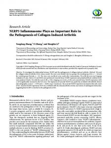
Figure 1: Streamlines at 30 m (AGL) over orography (in m) implemented by the model at 0300 UTC within Palma basin.
1999. Its characteristics are explored according to the proposals of Mahrt (1982) or the more recent work of Renfrew (2004) and a validation is performed through the radiative surface temperature field, which is compared with the field estimated from NOAA images. 2
SITE DESCRIPTION
Majorca is the largest island of the Balearic archipelago, located in the Western Mediterranean sea, 200 km offshore of the east coast of the Iberian Peninsula. It has a characteristic size of 100 km, with a large mountain range at its northwestern side (serra de Tramuntana), with an average height of 700 m ASL and maximum peaks of 1450 m. Another lower and discontinuous one is present at the south-eastern side (serra de Ll-
∗ Corresponding author address: Daniel Mart´ ınez, Grup de Meteorologia, Dpt. Fisica, Universitat de les Illes Balears, Carret. Valldemossa, km 7.5, 07122-Palma de Mallorca, Spain; email:
[email protected]
1
evant), with an average height of 300 m. At the central part of the island, there is a flat and elevated terrain, including a small central mountain called Randa with a height of 500 m. The topographical configuration of serra de Tramuntana, the elevated platform at the center and Randa mountain form the Palma Basin at the western side of the Isle. The Basin is almost closed and there is only one exit to the sea through the southern side. The south-eastern part of the basin contains a quasi bidimensional gentle slope parallel to the sea coast of almost constant angle. The drop from the mountain to the center of the basin has, firstly, a steep part of 100 m in 1 km (a 10% slope), then 50 m in 4 km (a 1.25% slope) and finally the drop of 200 m in 8 km to the center of the basin (a 2.5% slope). The terrain is agricultural, with fields of olive, carob and almond trees and some small pine woods. At the end of the slope, the Palma international airport is found. The line chosen to study the wind dynamics over the slope is between Cura (at the Randa mountain) and the airport. 3
DESCRIPTION OF THE FLOW
To perform this study, the Meso-NH model of the French community has been used (Lafore et al., 1998). Two domains are chosen, the largest one with a resolution of 5 km and the inner one of 1 km, covering only Majorca. The initial and boundary conditions are provided by the European Center of Medium-range Weather Forecasts (ECMWF) analyses. The simulation runs from 1200 UTC (12 local solar time) on January 5th, 1999 to the dawn of the next day, thus covering completely the 15hour-long night. It has been run on the ECMWF supercomputers. The vertical resolution is very fine near the ground, to be able to capture all the details of the low level flows: close to 3 m in the surface layer, with a stretching factor that leads the resolution to about 8 m at 500 m ASL and to 500 m at the model top. Such a fine vertical resolution implies very short timesteps (below 2 s), especially at mountain slopes. The runs and these results are further explained in Cuxart et al. (2006). The synoptic situation for the night of 5-6 January 1999 was characterized by a weak gradient of pressure. The archipelago was very close to the center of a winter high pressure system, with the flow coming from the southeast (of about 4 m s−1
Figure 2: Horizontal wind velocity and direction at 30 m (AGL) over orography (in m) implemented by the model at 1900 UTC, 0000 UTC and 0400 UTC (from top to bottom). Bold line represents the base of vertical cross-section chosen to study downslope flow dynamics. Dots indicate the points where variables from the model have been interpolated.
2
over the sea at 10 m), thus tangent to the slope direction. The skies were cloudless and the humidity was low. The situation was steady at the synoptic scale during all the run. With this configuration, the center of the island became an area of minimum wind speeds, able to develop freely motions determined by the topographical configuration. In particular, at low levels, the flat part of the Palma basin receives contributions from all the surrounding slopes. The W and NW parts seem to contribute as outvalley flows, whereas the rest of the orography acts as a generator of katabatic flows. The ensemble of flows converge at the center of the basin, where the cold air cumulates and is impelled to the sea driven by the pressure gradient that results from the warmer air above the water in the Palma bay. Figure 1 shows the streamlines distribution at 30m AGL within the Palma basin when motion is influenced by the complex terrain. At the eastern part of the Palma basin, a katabatic flow is well developed two hours after the sunset, blowing downslope from Cura towards the valley. Figure 2 shows the wind direction and velocity at 30 m AGL over the orography implemented by the model around the slope of interest at 1900 UTC, 0000 UTC and 0400 UTC. During the night, gravity flow turns to the right and then to the left but sustaining the downslope direction as the main wind component over the slope. As the flow arrives to the airport, it turns to cross-slope direction and joints with the land-to-sea flow. The wind direction at the airport remains nearly constant during the night. In Figure 3 the wind speed and potential temperature fields over the line Cura-airport at 0400 UTC are shown. A maximum of wind is generated downslope of the Randa mountain. At the change of slope the maximum is found at about 80 m above the surface and when the slope becomes steeper, the wind accelerates again, with a maximum of about 5 m s−1 at about 50 m AGL. When the downslope wind reaches the cold air in the basin it seems to split, with some air flowing close to the surface and the upper air above the cold area. The temperature takes lower values at the parts were the slope is less steep. 4
Figure 3: Vertical cross-section at 0400 UTC following the line Cura-airport. Top: wind speed (in ms−1 ). Bottom: potential temperature (in K).
KATABATIC FLOW DYNAMICS
In a rotated coordinate system, the momentum equation for a katabatic flow over a slope with 3
a constant inclination angle α can be written as (Mahrt, 1982):
200
(a)
19UTC 20UTC 21UTC 22UTC 23UTC 00UTC 01UTC 02UTC 03UTC 04UTC 05UTC
150
(1)
z (m)
1 ∂p 4θ ∂(w0 u0 ) Du =− +g sinα + f v − Dt ρ0 ∂x θ0 ∂z
where shallow convection and ”quasi-hydrostatic” approximations have been made, in which the hydrostatic equilibrium is present only for motion perpendicular to the ground (Mahrt, 1982 and Haiden, 2003). The velocities u and w are referred to the rotated axes, tangent and normal to the slope, respectively. Following Renfrew (2004), a two-layer model is assumed consisting of a katabatic layer as the lower one and a quiescent layer at higher level. A vertical integration of the momentum budget (1) from ground to katabatic-layer top (hk ), assuming that the temperature deficit and wind speed vanish at the top of the layer and at surface, respectively, yields: µ ¶ ∂uk uh − u k 4θk ∂uk = − uk + wk α +g ∂t ∂x hk θ0 g4θk ∂hk ghk ∂4θk − + f vk − θ0 ∂x θ0 ∂x (w0 u0 )h − (w0 u0 )sf c = − hk = Fadv + Fb + F4θk + Fh + Fcor + Fdiv
100
50
0 0
1
2
3
4
5
6
7
M (m s-2) 200
(b)
z (m)
150
100
50
0 282
284
286
288
290
θ (K)
Figure 4: (a) Wind velocity (in m s−1 ) and (b) potential temperature (in K) profiles every hour during the night at point 8 (see Figure 2 for location).
(2)
where small angle slopes are considered (sinα ≈ α, cosα ≈ 1). Here, uk , wk are katabatic-layer average velocities, uh is the velocity at the top of the layer, θ0 is a reference potential temperature and it is taken here as the value at the top of the layer, 4θk = θ0 − θk is the katabatic-layer potential temperature deficit, g is the gravitational acceleration, f is the Coriolis parameter, and (w 0 u0 )sf c , (w0 u0 )h are the vertical turbulent u-momentum fluxes at the surface and at the top of the layer. The Lagrangian derivative has been expanded and the cross-slope variation of uk has been neglected. Equation (2) contains the different forcings involved in the momentum equation: Fadv refers to the total advection, Fb is the buoyancy term that, by definition, is supposed to be the source of the katabatic flow, F4θk and Fh are referred to as the thermal-wind terms (Mahrt, 1982), which are relevant if the layer depth and the katabatic potential temperature deficit vary along the slope. Fcor is related with the Coriolis force and Fdiv represents
the divergence of turbulent vertical flux term and is related with the surface drag and the entrainment at the top. To apply the analysis to our case, a definition of the top of the katabatic layer is required. Although the present katabatic structure (represented in Figure 3) is quite stationary during the night, there is certain temporal variability point to point. Figure 4 shows the wind velocity and potential temperature profiles every hour during the night of 5-6 January 1999 for a given point located in the part with a 2.5% slope. These profiles are representative of the points affected by the downslope flow. Due to the relative unsteadiness of the regime and its spatial variability, here hk is considered to be the height of temperature inversion related with the maximum wind generated by the katabatic flow. 4
1000 900 800 700 600 500 400 300 200 100 0
(a) 19-20 UTC 02-04 UTC Orography
2
4
6
8
10
12
Z(m)
288 287 286 285 284 283 282 281 280 279 278 0
14
100 90 80 70 60 50 40 30 20 10 0
1000 900 800 700 600 500 400 300 200 100 0
(b)
0
2
4
6
8
10
12
Z(m)
hk(m)
x(km)
14
4.5
1000 900 800 700 600 500 400 300 200 100 0
(c) -1
uk(m s )
4 3.5 3 2.5 2 1.5 0
2
4
6
8
10
12
Z(m)
x(km)
14
3
1000 900 800 700 600 500 400 300 200 100 0
(d) -1
vk(m s )
2 1 0 -1 -2 0
2
4
6
8
10
12
Z(m)
x(km)
14
(e) -1
wk(m s )
0 -0.05 -0.1 -0.15 -0.2 0
2
4
6
8
10
12
1000 900 800 700 600 500 400 300 200 100 0
Z(m)
0.1 0.05
1000 900 800 700 600 500 400 300 200 100 0
Z(m)
x(km)
14
x(km)
2 -2
In Figure 5 the time-averaged values along the slope, two hours after sunset (1900 to 2000 UTC) and towards the end of the night (0200 to 0400 UTC), are shown for the relevant parameters of the above formulation. Since the flow at the end of the slope (0 to 5 km in Figure 8) merges with the downvalley wind, it is probably not well represented by the theory used here. The depth of the katabatic layer increases with time and potential temperature remains constant over the slope, whereas the lower layer cools around 3 K and its depth decreases at the foot. For the average velocities, uk describes an oscillatory behavior along the slope (that becomes more relevant at the second period) and its maximum values match with potential temperature crests, that are well correlated with the changes of slope. During the night, the maximum value of uk located at the end of the slope moves 1 km downslope and the rest of the extreme values strengthen. Nevertheless, cross-slope velocity vk changes significantly during the night except near the foot, indicating that the slope wind turns with time. Slope-relative vertical wind component wk (which is approximated to vertical component) alternates negative and positive values along the slope during second period (0200-0400 UTC). This behavior is consistent with the mass continuity principle in relation with the oscillatory distribution of uk . Banta et al.(2004) ran a simulation over the Great Salt Lake basin detecting bands of rising and sinking motions where the down-basin and canyon downslope flows converged. Such vertical velocities were about 5 cm s−1 , the same order of magnitude as the velocities simulated here. The locations with a higher velocity also have high values of surface turbulence flux due to an increment of the wind shear close to the surface. It is interesting to note that the momentum flux is, in general, one order of magnitude greater at the surface than at the top of the katabatic flow. This situation suggests that entrainment is not relevant and only surface friction can be considered, as for the flow described by Ball (1956). In other works (Renfrew 2004; Manins and Sawford 1979), entrainment arose as important as surface drag because a quiescent upper layer leads to an important wind shear. However, in present study, the wind velocity is significant above the katabatic layer and it has the same direction than slope flow. There-
θk (K)
Katabatic-layer average values
u’w’ (m s )
4.1
0.01 0 -0.01 -0.02 -0.03 -0.04 -0.05 -0.06 -0.07 -0.08 -0.09
(f)
(19-20H)sfc (19-20H)h (02-04H)sfc (02-04H)h 0
2
4
6
8
10
12
14
x(km)
Figure 5: Mean parameters for the katabatic-layer along the slope following the line Cura-Airport in Figure 2. Time-averaged values and standard deviation are plotted for two different periods of the night: 19002000 UTC and 0200-0400 UTC. (a) Mean potential temperature θk (in K), (b) katabatic-layer height hk (in m), mean velocities (in m s−1 ) (c) along-slope direction uk ,(d) cross-slope direction vk and (e) slope relative vertical direction wk , (f) kinematic momentum fluxes at the surface and at the katabatic-layer height 2 −2 5 (in m s ).
fore, a weak vertical gradient of u is present leading to a small value of vertical flux (w 0 u0 ) compared to what would exist if the upper layer was at rest. The changes in the slope, that are well correlated with the wind speed uk as mentioned before, seems to propagate upwards and are able to modulate the flow in the first thousands of meters above the ground. Figure 6 shows the streamlines over the Randa mountain at three different moments for the night. Air wind direction is modified by the mountain, leading to a steady configuration that seems to strengthen with time. Wind speed increases near the mountain peak and close to the points where slope changes. Terrain-generated gravity waves are stationary relative to the ground surface (Nappo, 2002) like the oscillatory behavior detected in the present katabatic flow. Further studies must be developed in order to confirm the hypothesis of a terrain-generated gravity flow.
4.2
Forcing terms from momentum equation
Figure 7 illustrates the forcing terms of the downslope momentum budget from equation (2). The buoyancy force Fb is balanced by momentum flux divergence Fdiv , specially at the beginning of the night, and the advection term Fadv . The latter not always slows the flow since it changes its sign along the slope. The thermal-wind terms F4θ and Fh are generally small and the Coriolis term Fcor is irrelevant due to the small spatial scale of the phenomena. Finally, Fres is the residual of equation (2) that also includes the Eulerian acceleration. Its sign is opposite to Fadv in almost every point, suggesting that the estimation of the total advection term is the main source of error. In order to improve the results, three-dimensional effects should be considered to represent the advection term. These results are in agreement with Mahrt (1982), who showed that gravity flows can be generally approximated by a balance between buoyancy acceleration and downslope advection of weaker momentum or/and the turbulent transport term. Such 2flows coincide with a Froude number u (F r = (g4θ/θk 0 )hk ) greater than one, as in present case, where F r > 1 along the slope (not shown), and the katabatic wind can be considered a shooting flow in terms of hydraulic theory. The point located at the upper part of the longer slope (about km 11) has a very small contribution of all the forcing terms. From this point
Figure 6: Vertical stream lines at the Randa Mountain following the direction of the line Cura-Airport in Figure 2 at different times. From top to bottom: 1900 UTC, 2300 UTC and 0300 UTC.
6
1000
4
(a)
4
(a)
900 3.5
700 600
0 500
-4
3 2.5 2 analytical solution Meso-NH
400
Fadv Fb Fdiv F∆θ Fh Fcor Fres
-2
Z(m)
F(m s-2)x10-3
2
uk (m s-1)
800
1.5 0
300
1000
2000
3000
4000
5000
6000
7000
8000
5000
6000
7000
8000
x(m) 200
4
(b)
100 3.5
-6
0 2
4
6
8
10
12
14
uk (m s-1)
0
x(km) 1000
(b)
4
3 2.5
900 2
800 1.5
700
0
0 500
300 hk Orography
-4
200 100
-6
0 0
2
4
6
8
10
12
2000
3000
4000
Figure 8: Solution for the downslope momentum equation (2) in the simple case of a shooting flow assuming constant hk for points over slope where buoyancy term is dominant. X-axis indicates the downslope distance respect to the 10th point in Figure 2. Timeaverage wind speed uk and standard deviation from simulation is also plotted. (a) 1900-2000 UTC and (b) 0200-0400 UTC.
400
-2
1000
x(m)
600
Z(m)
F(m s-2)x10-3
2
14
x(km)
4.3
Figure 7: The same as Figure 5 but for the forcing terms from the downslope momentum equation (in m s−1 ) at (a) 1900-2000 UTC period and (b) 0200-0400 UTC period. The average katabatic-layer height hk and the standard deviation (in m) are also plotted but relative to the orography line.
Mahrt’s analytical solution
Mahrt (1982) presented a simple solution for downslope momentum equation (2) to cases where main terms are Fb , Fdiv and Fadv . Neglecting the rest of forcings and assuming constant hk , downslope wind speed can be written as: n i o1/2 h −x −x uk = ue 2 1 − e( Le ) + uk 2 (0)e( Le ) · ¸1/2 hk hk g4θ/θ0 sinα ue ≡ Le ≡ (CD + k) CD + k
on, the buoyancy term grows downslope. It can be considered the origin of the buoyancy-driven flow. Another ”singular” point is where the katabatic flow meets the downvalley flow in the second period (km 6). Here, the buoyancy force is not balanced. The cross-slope average velocity vk changes its sign and wk is positive and significant. Also, the depth of the katabatic-layer is the largest of the slope and the vertically averaged potential temperature decreases 5 K, leading to important local gradients that increase the thermal wind terms (F4θ and Fh ).
(3)
where uk (0) is the katabatic layer mean velocity at some arbitrary point on the slope; ue is the solution for an equilibrium flow, a case where buoyancy acceleration only balances with turbulence term; and Le is a length scale related with the distance needed for the flow to adjust to the equilibrium case. CD and k are the drag and the entrainment or mixing coefficients, respectively, and here are calculated through the vertical turbulent flux of momentum at the surface and at the top of the 7
(w0 u0 )sf c uk 2
Figure 8 illustrates uk over the slope for points where the buoyancy term is dominant (from point about km 11 to km 4). Therefore, uk (0) represents the vertically averaged velocity at the point considered to be the beginning of the katabatic flow. To apply the solution (3), it is necessary to assume that the parameters ue and Le are constant. A representative value for all the points has been estimated from the simulation for both time intervals analyzed (1900-2000 UTC and 0200-0400 UTC). Table 1 summarizes the values for the parameters needed to plot Figure 8. The resulting length scale Le is similar to the downslope length scale and, consequently, the katabatic flow cannot reach the equilibrium regime.
800 700
-1
600 -2
500 400 300 200
-4
100 -5
0 0
2
4
6
8
10
12
14
x(km)
Figure 9: Surface cooling, obtained from the model and the available NOAA satellite images, computed with the model radiative temperatures at 1900 UTC and 0400 UTC, and the images at 1846 and 0405 UTC. (∆T = Trad (04U T C) − Trad (19U T C)).
5 A COMPARISON TO REAL DATA: SURFACE COOLING RATE In order to compare the katabatic flow simulated with real data, a method of validation for simulations implemented recently by Mira et al. (2006) has been applied. It consists of a comparison between the radiative surface temperature computed by the model with the estimated from NOAA IR imaginary. Since there are two NOAA images from the night of 5-6 January 1999 (1846 UTC and 0405 UTC), the radiative surface cooling rate has been calculated as:
analytical simple solution for downslope momentum equation in the case of a shooting flow.
1900-2000 UTC 0.004 30 m 1K 283 K 0.033 2.83 m s−1 2.93 m s−1 7500 m
900
-3
Table 1: Values used for the parameters present in
CD + k hk 4θ θ0 sinα uk (0) ue Le
1000 NOAA Meso-NH Orography
0
(w0 u0 )h ;k = uk 2
∆Trad (K)
CD = −
1
Z(m)
katabatic layer:
0200-0400 UTC 0.004 40 m 1.5 K 283 K 0.033 2.30 m s−1 4.14 m s−1 10000 m
4Tsf c = Tsf c (t2 ) − Tsf c (t1 )
(4)
Figure 9 shows the field 4Tsf c along the slope obtained from the satellite images and from the model outputs 1900 UTC and 0400 UTC. There is an agreement between both cooling rates at the upper part of the slope, where a local maximum cooling is reproduced at the same point. It coincides with the minimum of katabatic-layer mean velocity uk , in agreement with the conceptual scheme where, as the wind strength decreases, the surface turbulence becomes smaller and the lack of mixing leads to a decrease of radiative surface temperature. The difference of 6 K observed at the airport (x = 0 km) might be explained by the formation of a shallow fog reported by the airport observers at the end of the night. The model cannot reproduce this phenomenon because the humidity was not considered in this simulation.
The analytical simplified solution reproduces the tendency of the slopewind velocity from the simulation, which increases with the slope in both periods. The increasing of uk downslope is bigger during 0200-0400 UTC, but uk (0) is smaller. However, the solution (3) is very sensitive to changes in the parameters. For instance, arbitrary changes in the origin point uk (0) or in the estimation of hk , may lead to a simplified solution with a different tilt, losing the similarity with the tendency from the simulation results. Since the oscillatory behavior of uk is assumed to be related with terrain-generated gravity flows, the simplified solution cannot reproduce it. Besides, for katabatic simulated, hk is not constant and thermal wind terms are not enough smaller to be neglected in some specific points, specially during time interval 0200-0400 UTC. 8
6
References
CONCLUSIONS
Ball, F. K. (1956). The theory of strong katabatic winds. Aust. J. Phys. 9, 373–386. Banta, R. M., Darby, L. S., Fast, J. D., Pinto, J. O., Whiteman, C. D., Shaw, W. J. and Orr, B. W. (2004). Nocturnal low-level jet in mountain basin complex. Part I: Evolution and effects on local flows. J. Appl. Meteor. 43, 1348–1365. Cuxart, J., Jim´enez, M. A. and Mart´ınez, D. (2006). Nocturnal katabatic and mesobeta basin flows on a midlatitude island. Submitted to Mon. Weather Rev. Fleagle, R.G. (1950). A theory of air drainage. J. of Meteor. 7, 227–232. Haiden, T. (2003). On the pressure field in the slope wind layer. Notes and correspondence. J. Atmos. Sci. 60, 1632–1635. Haiden, T. and Whiteman, C. D. (2005). Katabatic flow mechanims on a low-angle slope. J. Appl. Meteor. 44, 113–126. Heinemann, G. (2002). Modelling and observations of the katabatic flow dynamics over Greenland. Tellus 54A, 542–554. Lafore, J. P., Stein, J., Asencio, N., Bougeault, P., Ducrocq, V., Duron, J., Fisher, C., H´ereil, P., Mascart, P., Pinty, J. P., Redelsperger, J.L., Richard, E. and Vil´a-Guerau de Arellano, J. (1998). The Meso-NH atmospheric simulation system. Part I: Adiabatic formulation and control simulation. Ann. Geophys. 16, 90–109. Mahrt, L. (1982). Momentum balance of gravity flows. J. Atmos. Sci. 39, 2701-2711. Manins, P.C. and Sawford B. L. (1979). A model of katabatic winds. J. Atmos. Sci. 36, 619–630. McNider, R. T. (1982). A note on velocity fluctuations in drainage flows. J. Atmos. Sci. 39, 1658–1660. Mira. A., Cuxart, J., Luque, A., and Guijarro, J. (2006). Mesoscale basin flows in the nocturnal boundary layer: modelling and verification. Proc. 17th Symposium on Boundary Layers and Turbulence. 22-25 May, San Diego, CA. Nappo, C. J. (2002). An Introduction to Atmospheric Gravity Waves. Academic Press, 276pp. Prandtl, L. (1942). Strmungslehre. Verlag Vieweg und Sohn., 382pp. Renfrew, I. A. (2004). The dynamics of idealized katabatic flow over a moderate slope and ice shelf. Quart. J. Roy. Meteor. Soc. 130, 1023– 1045.
A katabatic wind over a quasi bidimensional slope is analyzed. Its structure is practically permanent since the location and its general behaviour is maintained along the night, but it shows significant temporal variability. With an average depth of 40 m and a mean layer velocity of 3 m s−1 , the descending wind can twist around the downslope direction and the lower part of the katabatic flow adapts to the general configuration within the basin. The changes in the slope downhill induce changes in the behaviour of the flow that propagate upwards and amplify with time. An analysis of the momentum budget shows that buoyancy force is generally balanced by the momentum flux divergence and, in some cases, by the total advection. Latter term is not well parametrized since the two-layer model reduces the system to a two dimensional problem. Furthermore, surface drag is the most important component of Fdiv term, in detriment to entrainment which do not seem to have any relevancy in this case. Both scale analysis and hydraulic theory show that katabatic wind is in a shooting regime. The increment of mean katabatic-layer velocity uk along the slope is predicted for simple analytical solution and accomplished by the simulation. However, the steady wind oscillations cannot be explained by the katabatic theory since they seem to be related with waves generated by the terrain. This hypothesis must be confirmed in further work. Finally, this oscillating structure has a reflection of the surface temperature that is confirmed by the inspection of two available NOAA images during the night of interest. 7
ACKNOWLEDGEMENTS
The European Center for Medium-range Weather Forecasts (Reading, UK) is acknowledged for the access to its computing facilities, through the intermediation of the Spanish Met. Service (INM). Many thanks as well to the Centre National de Recherches M´et´eorologiques (Toulouse, France) for their support in the use of the Meso-NH model. J.A. Guijarro (INM) is also acknowledged for the discussion and A. Luque and A. Mira from UIB for the processing of the NOAA satellite images. This work has been partially funded by the research project REN2003-09435/CLI of the Spanish Ministry of Research.
9