EPJ Web of Conferences 147, 04003 (2017)
DOI: 10.1051/ epjconf/201714704003
EC-19
Series of powerful CW gyrotrons in the range 105 – 140 GHz Gregory Denisov2, Igor Kazansky1, Vladimir Malygin2, Elena Soluyanova1, Evgeny Tai1*, Aleksey Chirkov2 1
Gycom Ltd, Nizhny Novgorod, Russia Institute of Applied Physics, Nizhny Novgorod, Russia
2
Abstract. GYCOM in collaboration with Institute of Applied Physics (IAP) designed, fabricated and tested two different gyrotrons with similar to ITER parameters at 105 – 140 GHz frequency range. Set of gyrotron system beside the tube includes matching optic unit (MOU) and elements of evacuated transmission lines. One gyrotron system was installed and operates at plasma machines EAST / ASIPP / China, another system is delivered to KSTAR / NFRI / Korea.
1 Introduction Presented gyrotrons are similar to ITER gyrotrons in points of RF power up to 1 MW at the output window, duration of microwave pulses up to 1000 s, efficiency about 50 %. The gyrotron systems include matching optic unit (MOU) for HE11 waveguide mode forming, calorimetric load for full regime of operation, special pumping tee, RF two-directional switch, corrugated waveguides, miter bends and miter bend with bidirectional coupler. First of the mentioned gyrotrons was used at EAST machine for plasma heating experiments during 2015 2016 years. It has 140 GHz frequency, 1 MW power and maximum 1000 s longevity of CW operation. Second gyrotron is a two-frequency 105 / 140 GHz tube designed for plasma machine KSTAR. Output power of this tube is 950 kW at frequency 140 GHz and 800 kW at 105 GHz, maximum pulse duration is 300 s. The parameters of two-frequency tube were demonstrated already at GYCOM’s factory tests. Now equipment is under acceptance test procedure at the customer site. Set of delivery besides the tube includes two-frequency MOU with removable mirrors and calorimetric load. Both gyrotron systems use for operation standard liquids-free magnet JMTD-7T160 produced by company JASTEC, Japan. The series of gyrotrons will be continuing by new contracts with ASIPP and NFRI.
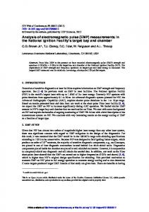
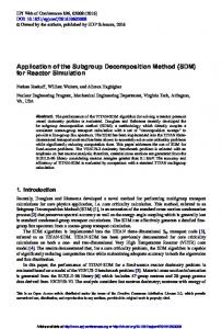
2 Features of gyrotron systems design Main feature of described gyrotrons consists in scheme of CPD insulation and is shown at the Fig.1. Classic ITER-like gyrotron has located above cryomagnet CPD ceramic, its body inside cryomagnet has positive relatively ground potential and correspondently is electrically insulated from cryomagnet warm bore. Described in this paper gyrotrons are based on located under cryomagnet CPD ceramic and have grounded tube body without HV insulation between gyrotron and magnet. “Lower” CPD insulator design differs by *
smaller insulator diameter (140 mm against 240 mm diameter in “upper” ceramic) and correspondently more simple system for ceramic cooling. Disadvantages of “lower” CPD insulator are smaller maximum recuperating voltages, correspondently smaller maximum efficiency (theoretically difference of efficiency is about 3%) and necessity of vertical transportation because of anode-cavity unit of gyrotron has long cantilever design.
a
b
Fig. 1. Scheme of gyrotrons supplement and insulation, a – “upper” CPD insulator, b – “lower” CPD insulator.
Other features of presented gyrotron tubes design are: stainless steel double wall body cooled by water between walls, cooled by water anti-arcs screen in cathode area, high temperature LaB6 emitter at cathode with middle diameter of 86 mm, relief BN window with 100 or 123 mm diameter, collector with combination of DC and AC sweeping coils. All presented gyrotrons are equipped by brazed by GYCOM diamond windows with aperture from 70 to 88 mm. Diamond disks for windows are produced by E-6 or by IAP and brazed by surface-type connection with direct diamond cooling or edge-type
Evgeny Tai:
[email protected]
© The Authors, published by EDP Sciences. This is an open access article distributed under the terms of the Creative Commons Attribution License 4.0 (http://creativecommons.org/licenses/by/4.0/).
EPJ Web of Conferences 147, 04003 (2017)
DOI: 10.1051/ epjconf/201714704003
EC-19
connection with diamond cooling via copper cuff. Cavity modes are TE22,8 for 140 GHz operation (for both types of tubes) and TE17,6 for 105 GHz (for two-frequency tube). Additional feature of two-frequency gyrotron system is utilization of removable mirrors in MOU design for minimization of time for frequency changing and convenience of application.
pressure in MOU and transmission line, change mirrors in MOU, pump out the MOU and transmission line, adjust regime of operation. This procedure takes in total about 12 hours.
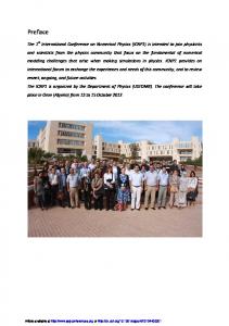
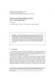
3 Experimental results Gyrotron systems were tested at GYCOM factory test bench. The scheme of the test is shown at Fig.2. Transmission line was pumped out through two ports. First port is located at MOU, second port is located at pumping tee. The pressure in transmission pump without RF power is less than 10-5 mbar. Vacuum two-directional switch directs the wave beam at short pulse calorimetric load with barrier window or at the full regime CW load.
CW load
Gyrotron Pumping tee with vaweguide filter
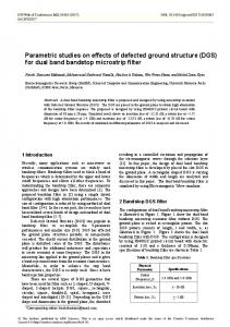
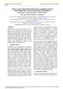
Fig. 3. Traces of 140 GHz operation at 0.92 MW / 300 s.
Short pulse load Switch
MOU Relief load
Miter bend (with directional coupler) Cryomagnet
Fig. 2. Gyrotron system assembled for the tests.
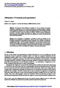
During 140 GHz / 1 MW / 1000 s gyrotron factory tests following regimes were demonstrated: 0.5 MW / 1000 s, 0.75 MW / 500 s, 0.92 MW / 300 s. Output power were measured at CW load by calorimetric method. Cathode voltage was varied from 44.5 to 46 kV, anode voltage – 22-23 kV, cathode current – 30-35 A. Traces of operation at maximum power are shown at Fig.3. It should be noted that experiments with gyrotrons provided by high temperature cathode were fulfilled without feed back system in the filament circuits. It causes some decreasing of cathode current after pulse start. The time of beam current stabilization is about 50 s and after that all operating parameters became stable. The calorimetric signals of powerful operation regime are presented at Fig.4.
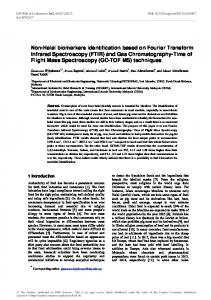
Fig. 4. Calorimetric signals of 140 GHz operation at regime 0.92 MW / 300 s.
Two-frequency 140 / 105 GHz gyrotron design differs from 140 GHz tube by cathode position. The gyrotron operation on both frequencies is accompanied by magnetic field correction in cathode area by using of special coil. Operation regimes at 140 GHz in both gyrotrons are very similar. Regime of operation at maximum power of 780 kW in the load at frequency 105 GHz is shown at Fig.5. Change of the gyrotron system frequency supposes following actions: change main magnetic field direction and magnetic field direction in AC section of collector coil, inject the atmospheric
Fig. 5. Two-frequency gyrotron operation at 105 GHz. Cathode current Ik=36.4 A, cathode voltage Uk=44 kV (negative to ground), anode voltage Ua=23.5 kV (positive to ground), power P=780 kW (in the load).
2