In: Virtual and Augmented Reality Applications in Manufacturing. Ong S.K and Nee A.Y.C, eds. Springer Verlag 2003.
17 The Intelligent Welding Gun: Augmented Reality for Experimental Vehicle Construction
Florian Echtler1, Fabian Sturm1, Kay Kindermann2, Gudrun Klinker1, Joachim Stilla3, Jörn Trilk2, Hesam Najafi1 1
Research Unit for Augmented Reality, Technische Universität München1 Forschungs- und Innovationszentrum (FIZ), BMW Group, Munich 3 BMW Technology Office, Vehicle Research, Palo Alto 2
This chapter presents the prototypical design and implementation of an Intelligent Welding Gun to help welders in the automotive industry shoot studs with high precision in experimental vehicles. A presentation of the stud welding scenario and the identified system requirements is followed by a thorough exploration of the design space of potential system setups, analyzing the feasibility of different options to place sensors, displays and landmarks in the work area. The setup yielding the highest precision for stud welding purposes is the Intelligent Welding Gun – a regular welding gun with a display attachment, a few buttons for user interactions, and reflective markers to track the gun position from stationary cameras. While welders operate and move the gun, the display shows threedimensional stud locations on the car frame relative to the current gun position. Navigational metaphors, such as notch and bead and a compass, are used to help welders place the gun at the planned stud positions with the required precision. The setup has been tested by a number of welders. It shows significant time improvements over the traditional stud welding process. It is currently in the process of being modified and installed for productional use. Keywords: Augmented Reality; Design Space for Augmented Reality Systems; High Precision Tracking; Information Presentation Metaphors; Experimental Vehicle Construction; Stud Welding
Correspondence to: Prof. Gudrun Klinker, Ph.D., Research Unit for Augmented Reality, Dept. of Informatics, Technische Universität München, D-85748 Garching, Germany. Email:
[email protected]
2!!!!!!17 The Intelligent Welding Gun: Augmented Reality for Experimental Vehicle Construction
17.1 Introduction Augmented Reality (AR) is a newly emerging technology! by which a user's view of the real world is augmented with additional information from a computer model (Azuma 1997; Milgram and Colquhoun 1999). With mobile, wearable computers, users can access information without having to leave their work place. They can manipulate and examine real objects! and simultaneously receive additional information about them or the task at hand (Klinker et al. 1999; Reiners et al. 1998; Tamura 2000; Underkoffler et al. 1999). Using AR technology, the information is presented three-dimensionally integrated into the real world. Exploiting people's visual and spatial skills to navigate in a three-dimensional world, AR thus constitutes a particularly promising new user interface paradigm. 17.1.1 Use of augmented reality in experimental vehicle construction In the automotive industry, experimental vehicle construction includes building a limited number of prototypes of a new model in order to validate product functionality and manufacturing processes. In addition unique prototypes are built for the purpose of evaluating new car concepts. Due to the small number of cars built in either case processes heavily rely on manual work rather than on automation. Highly automated manufacturing processes that are common practice in today’s automotive series manufacturing cannot be customized quickly enough in order to meet the requirements of fast and highly dynamic prototyping processes. Augmented reality shows great potential for improving manual work processes (Feiner et al. 1999; Friedrichs 2002; Mizell 2000). Due to high precision requirements, much time is currently spent determining the three-dimensional pose of car components before actually assembling them. For example, this is the case when workers weld steel studs into the body in white. This paper presents an AR-based solution to improve this process. 17.1.2 Structure of the paper The paper presented here starts with describing the current process of stud welding as well as the related shortcomings. Based on that, requirements for an improved process and different options for using AR technology including an analysis of strengths and weaknesses are discussed. The result of the discussion is the socalled Intelligent Welding Gun that has been implemented in a prototypical setting and is currently revised to be installed for productional use.
17.2 Stud welding for car prototypes!!!!!!3
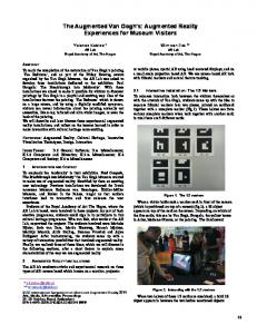
17.2 Stud welding for car prototypes In order to attach a large number of loose components such as wires and control devices to the car body, steel studs need to be welded at pre-specified positions into the car frame. To this end, experimental positions are specified by the car construction engineers, tested in prototypes and improved until a good arrangement has been determined and validated. Lists of experimental stud locations are delivered to the factory to be tested. Welders shoot the specified studs into the frames of a small series of car prototypes. Minimal deviations from the ideal position are allowed. To achieve such precision, current welding setups include two position locators (see Fig. 17.1.b) each consisting of an arm that can be moved at very high precision in three orthogonal directions. The position locators are permanently attached to two sides of a work table. The car frame is bolted to the work table at a pre-specified position. The stud welding process is currently divided into two phases and requires two workers to work together. In the first phase, one worker reads the coordinates of the selected stud position from the list (a computer printout) and operates the controls of the position locator until the arm of this apparatus is at the desired location. The second worker has two options for marking the stud location on the car frame: If an etching device is attached to the arm of the position locator, he makes a cross-like scratch on the frame. Alternatively, he can attach a laser pointer to the arm and use a felt pen to draw a mark on the car frame at the location that is illuminated by the laser. When all stud positions have been marked, the second phase begins. Welders place the studs at the specified positions using the welding gun (Fig. 17.1.a).
Fig. 17.1. Bolt welding equipment: a) welding gun, b) high precision position locator
4!!!!!!17 The Intelligent Welding Gun: Augmented Reality for Experimental Vehicle Construction
17.2.1 Use of augmented reality for more efficient stud welding Augmented Reality has the potential to greatly improve the efficiency of the stud welding process. With a suitable AR-setup, welders can skip the time-consuming first phase of determining all stud positions with the position locator and etching them into the car frame. Instead, an AR-system can guide welders with their guns directly to the specified position. Thus, time can be saved and precision can be gained since welders don't have to position two devices (first the etching device and then the gun) with an associated error margin each. 17.2.2 Requirements The following list describes the requirements that need to be met by an AR-based support system for stud welding applications. • Local work environment - The current work area covers approximately 7m x 5m x 3m. - Car frames are currently fixed to a work table. - A regular LAN is available. - The work area is well lit. • Restrictions to the use of AR-equipment - Due to the existence of magnetic fields and impulses, dust, vibrations, light arcs etc., the factory floor is a rather rough environment for computer hardware. - Due to metallic surfaces, car frames strongly reflect incident light. - Car frames include concave components. Some of the stud positions may not be easily visible from all locations - which can pose problems to optical tracking systems. • Work process - Approximately 300 studs need to be welded to every car frame. - Just before shooting studs, welders cannot see the actual stud positions since these are then occluded by the gun and the welders' hands. • Precision - Studs have to be positioned with high precision. • Usability - The system must be easy to use - in particular, it must not require large amounts of recurring setup, calibration or teaching time. - The system can be tethered (since the gun already requires a power cord). Yet, additional cabling along the welders' bodies should be avoided. - If a head-mounted display is used, it cannot strain the welders' eyes, and has to be very light-weight (due to the already considerable weight of the gun) - At least 10 frames per second must be presented.
17.3 Design options!!!!!!5
- The AR tracking system must be able to follow typical head and gun motions of the current welding process. Welders won't slow down for the sake of using augmented reality. • Safety - Welders cannot be distracted by new displays from already existing signaling equipment (e.g. warning lamps). • Further goals (optional) - Although the primary purpose of the AR-based stud localizer focuses on determining the current stud location with high precision, the system should also assist the welder in proceeding to the next stud without having to go back to the listing. To this end, an overview of the entire work area may be required - in addition to a high-precision presentation focusing on the current gun position. - The current use of a well-calibrated work table should be eliminated. - The system should not restrict welders' degree of mobility beyond their current limitations. - The setup should be as flexible as possible. In particular, the tracking equipment should be movable between several work areas.
17.3 Design options In a typical AR-setup, users wear a semi-transparent head-mounted display (HMD) to see augmentations to their current view of the scene (Curtis et al. 1998; Friedrichs 2002). This setup can be applied to the stud welding scenario to present welders the stud locations in a head-worn display. Yet, this is not the only conceivable setup; and it is not necessarily the best one. This section discusses available options for arranging AR-equipment in a scene and evaluates them with respect to the precision that can be achieved to place the studs on a car frame. 17.3.1 Design space Central to Augmented Reality are the concepts of information presentation (Julier et al. 2000; Schmalstieg et al. 2000) and user and object tracking (Rolland et al. 2001). Tracking systems can be based on various physical concepts, including electro-magnetic, ultrasound, inertial and optical principles (Azuma 1999; Rolland et al. 2001). Currently, optical trackers yield the most precise results. To achieve high precision, they rely on optical reference points (markers) which need to be placed throughout the work area (Kato et al. 2000; Park et al. 1998; State et al. 1996; Stricker et al. 1998). Thus, the following three kinds of devices need to be placed in the environment:
6!!!!!!17 The Intelligent Welding Gun: Augmented Reality for Experimental Vehicle Construction
- Displays (D) - Sensors (S) - Markers (M) In the HMD-based configuration that was introduced above, the display is placed on the welder's head. To determine the current head position, a camera is placed on the welder's head as well, tracking special markers that are set up in the environment. Since the position of the welding gun must be known as well, further markers are placed on the gun and tracked by the camera on the welder's head. Generalizing, from this configuration, four different options for placing each of the three kinds of devices (displays, sensors and markers) can be identified: -
unplaced, if a setup doesn't require a particular component (none) room-based within the work environment (room) user-based on the welder's head (user) instrument-based on the welding gun (tool)
The joint consideration of these options for placing displays D, sensors S and markers M yields a three-dimensional space with S x M x D = 43 = 64 potential solutions. Not all of these solutions are realistic. In particular, any solution that does not involve a display device can be ignored. Figures 17.2.a, 17.4.a and 17.6.a present the remaining 48 solutions, grouped according to three kinds of display positions D. Each figure presents the S x M = 16 possible positions of cameras and markers with respect to each display position and grades their feasibility on a scale from 0 (unusable) to 3 (very good). Some general properties of the relationships between cameras and markers can be observed (see Table 17.1): • It is useless to place both cameras and markers on the same devices since tracking algorithms exploit the dynamic nature or the ever-changing geometric relationship between camera and marker positions. Thus the diagonal entries don't make sense. They are marked with an “x” in Table 17.1. • The fourth diagonal entry represents situations in which Augmented Reality can be generated without using any tracking gear (untracked). If this is technically feasible, it is a very attractive solution (see section 17.3.2).
Table 17.1. Combinations of sensor and marker locations
M S none room user tool
none
room
user
tool
untracked markerless markerless markerless
x inside-out inside-out
outside-in x
outside-in x
17.3 Design options!!!!!!7
• In principle, a symmetry exists between the placement of markers and cameras, due to the reversibility of light rays. Accordingly, there are two general tracking concepts, called Inside-Out Tracking and Outside-In Tracking. Although the concepts are closely related, implementations and achievable precision, robustness and generality, as well as the costs vary greatly. - Inside-Out Tracking: Users wear one or more cameras attached to their head. The cameras track known, stationary markers in the environment to determine their own current position. Several software packages have been presented (HIT Lab 2003; Kato et al. 2000; Park et al. 1998; State et al. 2001; Stricker et al. 1998). Yet, they do not yet yield the level of precision and robustness that is required by the stud welding application. - Outside-In Tracking: Cameras are placed throughout the scene and pre-calibrated. Specific, predefined markers are attached to users and mobile scene objects. By tracking the markers, the stationary cameras can determine user and object positions at high precision (ART 2003). For example, the D-Track system by A.R.T. GmbH can track objects with precision levels shown in Table 17.2. • Markerless Tracking: Entries in the leftmost column represent markerless tracking approaches. Cameras are placed in the environment, on the instrument, or on the user, and algorithms track only general features that are available in the scene, on the user, or on the instrument. Concepts for achieving markerless tracking are currently intensely studied within the AR research community (Genc et al. 2002; Simon et al. 2000). Current first results are not yet robust enough to be recommended for the stud welding application. The best solutions are now discussed in more detail. 17.3.2 Projector-based solutions Recently, the concept of projecting information directly onto real-world objects rather than onto any kind of intermediary display has emerged (Bandyopadhay et al. 2001; Raskar et al 1998; Stetten et al. 2001). To this end, projectors are placed at suitable locations in the scene. Knowing the three-dimensional shapes and positions of all real objects, projector-based systems compute how images of virtual Table 17.2. Tracking performance of the A.R.T. D-Track system
Precision Absolute value Standard deviation Max. error Noise
Position 250mm 60mm 900mm 30mm
Angle 0.12 degrees 0.03 degrees 0.4 degrees 0.015 degrees
8!!!!!!17 The Intelligent Welding Gun: Augmented Reality for Experimental Vehicle Construction
Fig. 17.2. Projector-based setup: stud positions are projected by a projector onto the car frame. a) prototypical setup (no tracking), b) design space
objects need to be warped in order to generate a specific optical impression when they are projected onto the surfaces of the real objects. For the stud welding application, projectors or lasers can project the stud positions directly onto the car frame (Fig. 17.2, left). Welders can then see the stud positions on the frame independently of their own position. They don't need to be tracked. Accordingly, high importance is assigned to option in the projector-based solution space in Figure 17.2. (right). A potential problem can arise from occlusions. When welders approach an indicated stud position, they are likely to step into the light beam that is cast from a projector onto the car frame. Such occlusion effects can be reduced when several projectors each contribute to the scene augmentations. If users are tracked, their current position (and silhouette) can be taken into account by an algorithm to compute the optimum contribution of each projector to generate a stable illumination level for the augmentations even when light from some of the projectors is blocked. Accordingly, Figure 17.2. (right) suggests projector-based setups in combination with an outside-in tracking component in which stationary cameras in the environment track markers attached to both welders and welding guns. Alternatively, an inside-out setup can be used in which cameras are placed on both the user and the gun, tracking markers that are placed in the environment. However, such user tracking is highly complex, requiring elaborate camera equipment. It is unlikely to yield results of satisfactory precision in the short-term future. Therefore, these approaches have less importance. The achievable precision of projector-based setups depends on the resolution of the image that is projected from the projector onto the surface. Fig. 17.3 shows a setup that is achievable with current technology. When projecting a 1024 x 768 pixel image onto a 3m x 2m work area (minimal size of a car), each projected pixel covers a 3mm x 2.5mm rectangle - if it is projected onto a surface that is oriented orthogonal to the projected ray.
17.3 Design options!!!!!!9
Fig. 17.3. Achievable precision for the projector-based setup
Higher resolution can be achieved by placing several projectors side-by-side. Yet, this setup is physically very complex and expensive. Slightest misalignments between the projectors will result in shadow images of stud positions, causing welders to mistrust the system. 17.3.3 HMD-based solutions The classical approach of Augmented Reality consists of using a head-mounted display (HMD) to present scene-based information to a user (Curtis et al. 1998). For the stud welding application, current stud positions are shown in the HMD according to the current user position (Fig. 17.4, left). Figure 17.4. (right) indicates that there are four potential solutions which involve the use of an HMD. • Solution 1 suggests using a head-mounted display to which specific markers are attached. According to the outside-in tracking concept, the markers are tracked by stationary cameras that are installed on the outskirts of the scene. • Solution 2 suggests using an inside-out tracking concept. Yet, due to the lack of precision in the current demonstration systems in this domain, the outside-in approach is currently more suitable for the stud welding application. • Solutions 3 and 4 represent markerless tracking approaches, placing cameras either in the environment or on the user. Current first results are not yet robust enough to be recommended for the stud welding application.
Fig. 17.4. HMD-based setup: stud positions are shown on a display attached to the welder’s head. a) prototypical setup (outside-in tracking), b) design space
10!!!!!!17 The Intelligent Welding Gun: Augmented Reality for Experimental Vehicle Construction
Fig. 17.5. Achievable precision for the HMD-based setup
The achievable precision of HMD-based setups is considerable. According to Table 17.2, outside-in tracking technology can determine object positions within a small operating area with a maximal error of 0.9mm. In addition to the positional error, the angular error (0.4 degrees) needs to be considered. When welders are operating the welding gun at arm's length (assumed to be approximately 0.5m), the virtual studs are presented on the display with a positional error of e = 500mm * tan 0.4, which is approximately 3.5mm (see Fig. 17.5). The overall error thus accumulates to more than 4mm. 17.3.4 Instrument-based solutions As a third option, augmentations can be provided on a tracked portable display which users carry along with them. The display shows augmentations that are registered to the world behind the display. Such frame-based augmentations have been proposed by Rekimoto and others (Newman et al. 2001; Rekimoto et al. 1998). They are receiving increasing attention because they are able to provide users with scene augmentations in a less immersive way than HMDs, thereby alleviating issues of user safety. The augmentations are typically presented with respect to scene objects behind the display - along the perpendicular line of sight. Parallax problems arise when the is user looking at the display from an non-orthogonal angle. In the stud welding application, a small display can be attached to the welding gun. By tracking the gun, the AR system can present stud positions relative to the current gun position and indicate to the user in which direction the gun must be moved in order to approach the next stud.
17.3 Design options!!!!!!11
Fig. 17.6. Instrument-based setup: stud positions are shown on a display attached to the welding gun. a) prototypical setup (outside-in tracking), b) design space
Figure 17.6. (right) presents four options to show studs on the welding gun. • Solution 1 proposes an outside-in setup, using cameras in the scene to track markers on the gun (see Figure 17.6., left). • Solution 2 proposes the symmetrically reversed inside-out setup, with a camera on the welding gun and markers in the scene. This approach is not useful in the stud welding application because cameras on the welding gun significantly restrict the welders' ability to operate the gun in tight spots. • Solutions 3 and 4 represent markerless tracking approaches. Current first results are not yet robust enough to be recommended for the stud welding application. The instrument-based approach yields better precision than the HMD-based approach because stud positions are tracked close to the tip of the gun rather than at arms' length at the HMD. Just before welding, the gun is directly at the car frame and the angular imprecision can be discarded. In consequence, studs can be welded with 0.9 mm precision (Fig. 17.7).
Fig. 17.7. Achievable precision for the instrument-based setup
12!!!!!!17 The Intelligent Welding Gun: Augmented Reality for Experimental Vehicle Construction
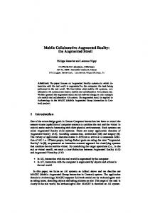
17.4 Conceptual design and prototypical implementation The general analysis of design options shows that the instrument-based solutions in section 17.3.4 yield the highest precision. In consequence, we have built the Intelligent Welding Gun (Fig. 17.8). The gun has an attached display to guide welders to the next stud location. Tracking is achieved using an outside-in tracking system with a set of stationary cameras that track highly reflective markers on the welding gun and on the car frame. Besides the precision requirement, the Intelligent Welding Gun also satisfies the most important other issues that were addressed in section 17.2.2. Its setup is minimal and can be moved back and forth between several work areas. Since no HMD is used, welders still have free sight of other instruments in their environment. Furthermore, they don't wear any gadgets on their own body and are thus not tethered to the apparatus. Accordingly, they are free to start and stop using the system spontaneously. In principle, the Intelligent Welding Gun no longer depends on using the well-calibrated work table with its position locators. The current setup still uses the work table in order to evaluate the positional quality of the results.
Fig. 17.8. Intelligent Welding Gun with display and markers
17.4 Conceptual design and prototypical implementation!!!!!!13
17.4.1 System overview The software system for the Intelligent Welding Gun consists of three major components (Fig. 17.9): a renderer, a tracker, and a set of interfaces. Initial versions of the system were implemented using the very flexible DWARF system (Bauer et al. 2001), providing the means to try various options before settling on a demonstration system that was installed and tested at BMW. In the demonstration system, the first two components each consist of pre-existing products. For proper use of these components in the stud welding application, the third component provides the required interfaces both for human interaction with the Intelligent Welding Gun and for access to BMW's information infrastructure. Several interrelated graphical interfaces are provided to the welder such that welding information can be understood at several levels of granularity. Each component will now be discussed in detail. 17.4.2 The tracking component The Intelligent Welding Gun is based upon the ARTrack1 tracking system of A.R.T. GmbH (ART 2003) since it is able to achieve the required precision in positioning the studs on the car frame.
Fig. 17.9. System overview
14!!!!!!17 The Intelligent Welding Gun: Augmented Reality for Experimental Vehicle Construction
Fig. 17.10. Infrared cameras and reflective targets of A.R.T. GmbH
Since ARTrack1 is an optically-based outside-in tracking system, it principally has limitations when operating in concave spaces. This may be the case when the car frame has been assembled into a complex three-dimensional structure. Yet, a significant amount of stud welding can be completed while operating with approximately convex substructures of the frame and by flipping it upside-down in a rotary sling.
17.4.2.1 ARTrack1 ARTrack1 consists of four or more special-purpose infrared cameras with a builtin infrared flash (Fig. 17.10.a). The flash is reflected from specifically designed tree-like arrangements of targets (Fig. 17.10.b) that are attached to mobile objects in the scene. Each camera has a built-in dedicated processor to detect up to 10 targets in image streams at 60 Hz. All cameras are calibrated in an initialization procedure. In a central processing unit, the DTrack software system receives 2D target positions from all cameras. It determines matching targets and computes their 3D location using the camera calibration data for multiple-view (n-ocular stereo) triangulation. For medium-sized targets (~10cm), the system achieves positional precision of ± 0.25mm and orientational precision of ± 0.12 degrees in rooms of 4m x 4m x 4m size (see Table 17.2). The resulting 3D data is made available to application systems via a 100Mbit/s ethernet connection (UDP/IP).
† 17.4.2.2 Camera installation
†
The n-ocular stereo algorithm requires that the relative position of the cameras with respect to one another does not change. Individual camera motions - e.g. due to vibrations of the floor caused by heavy machinery - result in deteriorated tracking data. For this reason, it is not recommended to place the cameras on tripods on the factory floor. Stationary placement along the walls or at the ceiling is not good either because such structures may also be subject to vibrations and furthermore - because such setup requires the system to be permanently installed in a single location.
17.4 Conceptual design and prototypical implementation!!!!!!15
Fig. 17.11. Camera installation on a fixed rectangular frame above the car – with associated coordinate systems
Since the stereo algorithm requires only a stable relative position of all cameras with respect to one another but not a fixed absolute position, the setup for the Intelligent Welding Gun places all cameras on a rigid steel frame and hang the frame from the ceiling (Fig. 17.11) (Zürl 2002). The overall setup thereby is free to swing and balance out any vibrations. It can also easily be moved back and forth between several welding platforms.
17.4.2.3 Target placement on the car frame and on the welding gun Reflective targets are placed across the car frame in order to register the car frame to the movable camera set (Figs. 17.11, 17.12). Due to these targets, the ARTrack1 system can determine the camera-to-car registration on a continuous basis. The camera-to-car registration also provides the Intelligent Welding Gun with much additional flexibility: welders can move the car frame freely during the stud welding process. For example, they can roll it over in a rotary sling to allow for much more convenient access to the bottom side of the frame.
16!!!!!!17 The Intelligent Welding Gun: Augmented Reality for Experimental Vehicle Construction
Fig. 17.12. Targets on parts of the car frame
Targets are also required on the welding gun. Standard targets, as provided by A.R.T. GmbH (Fig. 17.10.b), cannot be used. They are too bulky and extend too far from the gun, thereby hindering welders during operation in tight cavities. Instead, the Intelligent Welding Gun has a specially designed target, consisting of several spherical markers that are attached asymmetrically directly to the gun (Fig. 17.8).
17.4.2.4 Coordinate systems In the intelligent gun application, several devices and objects each define their own local coordinate system (Fig. 17.11). • The four tracking cameras define a coordinate system, ART, that is determined during the camera calibration procedure (section 17.4.2.5.1). • The tracking target on the welding gun defines a coordinate system on the gun, WG. The relationship between the cameras and the welding gun, T ART-WG, is determined by the ARTrack1 system (sections 17.4.2.1 and 17.4.2.3). • The coordinate system WGT describes the tip of the gun - which is critical to the required precision in the welding application. The relationship between the gun and its tip can be formulated by a transformation TWG-WGT (section 17.4.2.5.2).
17.4 Conceptual design and prototypical implementation!!!!!!17
Fig. 17.13. Hierarchy of coordinate systems
• The coordinate system CF describes the real car. Its position, relative to the tracking cameras, is defined by tracking targets on the car and described by the transformation TART-CF (sections 17.4.2.1 and 17.4.2.3). • The coordinate system CAD describes the virtual model of the car, as well as the stud positions. The origin of the CAD model is typically defined to be in the center of the front axle. The transformation between the physical car frame and the CAD model is described by the transformation TCF-CAD (section 17.4.2.5.3). The geometric relationships between all coordinate systems can be described in a scene graph (Fig. 17.13). Transitions between coordinate systems are formulated as compositions of linear transformations.
17.4.2.5 Camera calibration and pose estimation 17.4.2.5.1 Camera calibration Camera calibration is performed by placing a calibration object in the field of view of the cameras. The object has several reflective targets, whose relative 3D positions are known with very high precision. The pose of the calibration object determines the ART coordinate system. A.R.T. GmbH provides a wand kit for this purpose which consists of a calibration racket and a wand. By moving the wand (a pre-measured bar with two targets) through the desired tracking area during the calibration procedure, a virtual scatter plot is created. The scatter plot is used to estimate the relative poses of the cameras with respect to one other. To this end, the residual values of the respective triangulation processes are minimized. The accuracy of the tracking data inside the area covered by the wand is higher than outside of it. For our purpose the entire area on the welding platform is covered by the wand in order to achieve high accuracy wherever studs need to be welded.
18!!!!!!17 The Intelligent Welding Gun: Augmented Reality for Experimental Vehicle Construction
17.4.2.5.2 Pose estimation for the tip of the welding gun The position of the tip of the welding gun, WGT, is determined using another calibration procedure provided by A.R.T. GmbH. This is done by rotating the instrument with some targets (e.g., the welding gun) about the desired point (e.g. the tip) and using the respective tracking data to determine the rotation center about which the targets were rotated. The coordinate system of the tip is then defined by the translation of the origin of the coordinate system of the instrument targets to that center. 17.4.2.5.3 Pose estimation for the car frame To determine the transformation T CF-CAD between the real car (defined by tracking targets on the car frame, CF) and the CAD model of the car, CAD, the Intelligent Welding Gun exploits the fact that some car features can be located rather precisely on the real car. For example, places of high curvature, a drilled hole or a door knob can be identified very precisely both on the real car frame and in the CAD model. To this end, the gun has to be pointed during the calibration phase at these locations on the real car. Since the tip of the gun is calibrated and tracked, the real position of these locations can be determined with high precision. The result is a set of n points p i = [xi ,yi ,zi], i Œ 1,...,n, for which the relationship between the position in the CAD model, pi.CAD, and the respective real position in the ART camera coordinate system, pi.ART, is known. The relationship can be formulated as a system of linear equations to define the transformation matrix TARTCAD between the real (ART) coordinate system and the origin † of the virtual (CAD) coordinate system:
pi.CAD = pi.ART o TART -CAD Numerical methods for least square error minimization yield the transformation matrix TART-CAD with minimal error:
min
TART -CAD
† ( p o  i.ART TART -CAD - pi.CAD )2 i
The resulting Matrix T ART-CAD describes the transformation between the ART camera coordinate system and the car model. However, this transformation is a composition of two steps (Fig. † 17.13): the transformation TART-CF from the ART cameras to the target coordinate system on the car frame, followed by a transformation T CF-CAD from the coordinate system of the car frame to the origin of the CAD model in the center of the front axle.
TART -CAD = TART -CF o TCF-CAD Whenever the cameras (or the car frame) moves, the transformation TART-CF changes, whereas the subsequent transformation TCF-CAD is unaffected. This con-
†
17.4 Conceptual design and prototypical implementation!!!!!!19
stant offset between the origin of the coordinate system on the car frame and the CAD model can be computed as -1
TCF-CAD = (TART -CF ) o TART -CAD 17.4.3 The interface component: Access, visualization and interactive manipulation of the stud positions † The Intelligent Welding Gun accepts lists of studs that are provided in Excel spreadsheets, determining a unique stud ID, its position (x,y,z), its orientation, as well as a description of its status and comments. By default, the studs are ordered by their x, y, and z position. They can be resorted by other criteria upon user request. Two graphical display schemes are used to present the stud information to the welders: an AR-based view and a list. Fig. 17.14 shows a schematic presentation of both views. The AR-based view is shown both on a stationary computer console next to the car frame and on the display that is attached directly to the welding gun. The stud list is only available on the computer console.
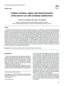
17.4.3.1 Information presentation for the AR-based view The AR-based view (upper left corner in Fig. 17.14) is intended to be the primary source of information on the Intelligent Welding Gun, assisting the welder in placing the currently selected stud with high precision on the car frame. This view is shown on the gun itself and thus reacts most directly to the welder's gun motions. Fig. 17.15 shows its use during a live demonstration of the system.
Fig. 17.14. Two views of the stud information
20!!!!!!17 The Intelligent Welding Gun: Augmented Reality for Experimental Vehicle Construction
Fig. 17.15. Intelligent Welding Gun in operation, indicating the current stud location in the AR-based view
The display shows several concentric rings in analogy to the notch and bead metaphor of real guns. The current stud is represented by a virtual sphere. It marks the location on the car frame where the new stud must be shot. When the welder points the gun in the direction of the stud position, the sphere becomes visible on the display - moving across the screen according to the gun's motions. When the welder 'catches' the sphere in the center of the concentric rings, he has oriented the gun properly toward the new stud position. Depending on the gun's distance from the car frame, the sphere changes its size until the tip is directly in front of the specified stud location – and the sphere has grown to entirely fill the center of the concentric rings. The width of the concentric rings indicates margins within which the welder has to operate to achieve acceptable precision. When the welder points the gun in a direction that is far from the stud location, the sphere is not shown on the AR-display. To help the welder find the stud, the display shows an arrow that points in the direction of the stud in analogy to a compass metaphor. Once the stud is in sight, both the arrow and the sphere are seen on the display.
17.4 Conceptual design and prototypical implementation!!!!!!21
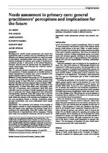
Fig. 17.16. Push buttons on the Intelligent Welding Gun
17.4.3.2 Interaction facilities Four push buttons are attached to the back of the welding gun (Figs. 17.15 and 17.16). They allow the welder to progress through the stud list and provide essential feedback without having to go back to the computer console. • Left button: Error If the current stud cannot be welded at the indicated position, the welder pushes this button to record this problem as a comment in the stud list. The stud is classified as erroneous. • Right button: OK Whenever the welder places a stud, he presses this button afterwards. The stud is classified as done. • Lower button: Next The welder proceeds to the next stud that has not yet been classified as done or erroneous. By pressing the button several times, he can skip studs. • Top button: Back The welder goes back to a previous stud that hasn't been placed yet. 17.4.4 The rendering component VD2 (VRCom 2003), an existing high-performance rendering system for virtual reality applications, was used as the basis for displaying stud information. Although the overall graphical needs of the Intelligent Welding Gun are not yet very high, future extensions to the application (e.g., a high-quality overview of the entire car) can be expected to require more performance. Since VD2 is already used at BMW to render complex virtual reality scenery with high functionality, it was a good, compatible choice for the Intelligent Welding Gun.
17.4.4.1 VD2 VD2 is an OpenGL-based large, monolithic system capable of quickly rendering large scenes. It reads scene descriptions from a file and represents them internally as a scene graph. The IDEAL device manager is in charge of integrating real-time data from external devices. This way, trackers can be attached to specific objects in the scene graph, as well as to the camera viewpoint.
22!!!!!!17 The Intelligent Welding Gun: Augmented Reality for Experimental Vehicle Construction
In the rendering loop, VD2 determines the current location of all tracked devices and alters the positions of their associated virtual objects. It then renders the current view of the scene. Several hooks (DSO-calls) into the system allow application developers to inject own code during initialization time and during the main rendering loop into the system. Via such hooks, developers can have direct access to the scene graph and modify it dynamically in order to alter properties of virtual objects.
17.4.4.2 Scene graph Fig. 17.17 shows the scene graph of the Intelligent Welding Gun application. It consists of two subtrees. The left branch is related to objects that are associated with the mobile welding gun. The right branch is related to objects that are described relative to the CAD coordinate system. As described in section 17.4.2, live tracking operations and offline pose estimation routines determine the relationships between the coordinate systems of the ART cameras, the tip of the welding gun WGT, and the CAD model (shown inside a gray box in Fig. 17.17). For the intelligent gun application, the scene graph is extended with further nodes in order to represent the visualization metaphors notch and bead, compass, and the current stud.
Fig. 17.17. Scene graph for presenting stud information on the Intelligent Welding Gun
17.5 Results and next steps!!!!!!23
• Notch and bead have a permanent position relative to the tip of the welding gun. In the scene graph, they are represented as a subtree NB of the WGT node. The graphical representations of notch and bead - e.g., as a set of concentric rings - are provided as external data files and integrated into the scene graph at initialization time. A permanent transformation describes their fixed offset from the tip of the gun. • Stud positions are provided relative to the CAD coordinate system. Accordingly, a node ST is generated as a child of the CAD node. The current stud is displayed as a sphere. When the welder selects a new stud, the ST node is updated to show the new location. Such updates to the scene graph are achieved via DSO-calls, via which application programmers can insert application-specific code into the rendering loop. Such code has direct access to the scene graph of the Intelligent Welding Gun application. Knowing its exact structure, it can be traversed to reach and manipulate the ST node. • The compass is an arrow that points from the tip of the welding gun WGT toward the location of the current stud ST. The current implementation describes the compass node, C, relative to the stud node, ST. Using the DSO facility, the current position and orientation of the arrow is recomputed in each iteration of the rendering loop. The tip of the arrow points toward the ST-node. Its back end is determined by traversing the scene graph from ST node upward to the global ART reference frame and then downward to the WGT node applying all associated coordinate transformations along the way.
17.5 Results and next steps A prototype of the Intelligent Welding Gun has been built and successfully demonstrated and tested with a number of workers on site. To this end, workers were asked to weld 10 studs at various locations on a car frame. In comparison to a second group of workers who welded the same number of struts the standard, non-augmented way, workers using the Intelligent Welding Gun were able to quadruple the speed while staying well within the precision requirements. Furthermore, workers were generally quite satisfied with using the intelligent gun. Worker feedback indicates that the welders were content with the overall system - especially with the work improvement that resulted from being able to weld the studs in a one-phase process rather than as a combination of a markup and welding phase. Yet, the current prototype was not yet able to satisfy the welders' expectations with regard to the ease of use. In particular, the gun was more bulky and thus less maneuverable. This was a great hindrance in tight cavities, while also tiring the workers physically. Second, the physical nature of the welding process required welders to press the gun to the car body just before welding a stud. During this final operation, misplacements could happen that were currently not recorded by the welding gun. The notch and bead metaphor were not yet so-
24!!!!!!17 The Intelligent Welding Gun: Augmented Reality for Experimental Vehicle Construction
phisticated enough to provide welders with feedback about the achieved precision, once a stud was placed. Overall, the welders accepted the new system in spite of the ergonomical and design deficits because the results of the functional aspects (quality, process improvement) could convince them. Due to the speed improvements and in response to the user feedback, a new, improved version of the Intelligent Welding Gun is currently being built which will be put to daily productive use in experimental vehicle construction and completely replace the traditional stud welding process. To this end, the gun frame is redesigned such that the display, the markers and interactive control devices are more tightly integrated into the gun, thereby reducing the weight and size of the gun. The welding software is integrated more tightly with the company IT infrastructure, retrieving welding instructions and indicating the position at which the stud was actually placed. The display metaphors are also extended. The notch and bead presentation shows the virtual car model in the background, as seen through the tip of the welding gun. Welders can zoom in an out to gain an overview or to focus on the selected welding spot with high precision. In addition to this guncentered (ego-centric) presentation, welders have access to room-centered (exocentric) presentation that is shown on a stationary display. It shows the work area from a bird’s perspective, displaying the virtual car model, the location of the current and/or further studs, as well as the current location of the welding gun within the scene. A new metaphor, a rubber band connecting the tip of the gun with the next stud, is used in the overview presentation to help welders orient themselves and find new studs at non-adjacent locations. The new version is currently being implemented and tested.
17.6 Summary In this paper, an approach for building an Intelligent Welding Gun was presented. The approach is based on the analysis in section 17.3, indicating that the most precise approach to stud welding involves tracking a mobile instrument (gun) and presenting information on a display attached to the gun rather than to the user's head. The result is a new design of an Intelligent Welding Gun for experimental vehicle construction. The gun is equipped with a display, as well as with specially designed tracking targets such that an outside-in tracking system can track the gun via a set of stationary cameras on the outskirts of the scene. In order to achieve maximal flexibility and stability, the cameras are installed on a rigid frame. The frame itself can be moved freely within the scene - as long as the relative position of the cameras with respect to one another remains constant. The camera-to-car calibration is determined by targets that are attached to the car frame. As a result, it is possible to move both the camera frame and the car frame without a need to recalibrate the system. Accordingly, there exists significant potential to alter the overall welding process in the long run by allowing welding operations to be performed more flexibly.
Acknowledgments!!!!!!25
Different concepts for finding and aiming at a stud position were proposed and implemented. The notch and bead metaphor was well suited to the task of placing the stud with sufficient precision. The compass was designed to help welders navigate between studs. Options for including further visualization schemes, such as an overall, bird's eye overview of the system are currently under development. The current implementation of the Intelligent Welding Gun relies on technology that has been used reliably at BMW for many years - in particular, on VD2, that is being used in many high-performance virtual reality presentations. Due to this reuse of standard components, the newly designed intelligent welding can be easily included in other graphical applications at BMW. A prototypical version of the Intelligent Welding Gun has been installed and tested on the factory floor at BMW. Preliminary results show that the new system is able to yield significant improvements in speed while also yielding small quality improvements. Welders were able to adapt to the new gun after minimal instruction time. Although the current system is only prototypical, the questionnaires indicated that welders were ready to accept it due to the improvements to the work process. Further development to integrate the system completely into the environment is under work. We expect the Intelligent Welding Gun to be a stepping stone towards a new class of user interaction paradigms, allowing workers to interact simply and intuitively with the computer system to fulfill their welding assignment. In this respect, results or this work are relevant to applications of Augmented Reality extending aside from welding setups. They can be transferred to other automotive applications and beyond.
Acknowledgments We are thankful to many people at BMW, especially Willibald Fürst, Hubert Zausinger, and Alfred Neureiter, for discussing various iterations of plans and concepts with us during the course of the entire project and for helping us organize the testing phase on the factory floor. Konrad Zürl and Armin Weiss of A.R.T. GmbH participated in many of the discussions and provided valuable advice (Zürl 2002). We would further like to thank numerous people of the AR-Group at TU Munich. We used the in-house DWARF system (Bauer et al. 2001) for initial implementations of the Intelligent Welding Gun to demonstrate a proof of concept for using the notch and bead and the compass metaphors. The Intelligent Welding Gun project is part of ARVIKA (Friedrichs 2002).
26!!!!!!17 The Intelligent Welding Gun: Augmented Reality for Experimental Vehicle Construction
References ART GmbH (2003) ARTrack1. On-line documentation at http://www.ar-tracking.de Azuma R (1997) A survey of augmented reality. Presence, special issue on Augmented Reality, 6(4):355-385 Azuma R (1999) The challenge of making augmented reality work outdoors. In: Proc Int Symp on Mixed Reality (ISMR’99), Yokohama, Japan, Springer Verlag, pp 379-390 Bandyopadhay D, Raskar R, Fuchs H (2001) Dynamic shader lamps: Painting on movable objects. In: Proc Int Symp on Augmented Reality (ISAR’01), New York, IEEE, pp 207-216 Bauer M, Bruegge B, Klinker G, MacWilliams A, Reicher T, Riss S, Sandor C, Wagner M (2001) Design of a component-based augmented reality framework. In: Proc Int Symp on Augmented Reality (ISAR’01), New York, IEEE, pp 45–53 Curtis D, Mizell D, Gruenbaum P, Janin A (1998) Several devils in the details: Making an AR app work in the airplane factory. In: Proc Int Workshop on Augmented Reality (IWAR’98), San Francisco, AK Peters, pp 47-60 Feiner S, MacIntyre B, Höllerer T (1999) Wearing it out: First steps toward mobile augmented reality systems. In: Proc Int Symp on Mixed Reality (ISMR’99), Yokohama, Japan, Springer Verlag, pp 363-377 Friedrichs W (2002) ARVIKA Augmented Reality for Development, Production, and Service. In: Proc Int Symp on Mixed and Augmented Reality (ISMAR’02), Darmstadt, Germany, IEEE. See also: http://www.arvika.de/www/pdf/IVIP Forum e.pdf. Genc Y, Riedel S, Souvannavong F, Akinlar C, Navab N (2002) Marker-less tracking for AR: A learning-based approach. In: Proc Int Symp on Mixed and Augmented Reality (ISMAR’02), Darmstadt, Germany, IEEE, pp 169-175 HIT Lab (2003) AR Toolkit library. On-line documentation and code at http://www.hitl.washington.edu/people/poup/research/ar.htm Julier S, Lanzagorta M, Baillot Y, Rosenblum L, Feiner S, Höllerer T, Sestito S (2000) Information filtering for mobile augmented reality. In: Proc. Int Symp on Augmented Reality (ISAR’00), Munich, IEEE, pp 3-11 Kato H, Billinghurst M, Poupyrev I, Imamoto K, Tachibana K (2000) Virtual object manipulation on a table-top AR environment. In: Proc Int Symp on Augmented Reality (ISAR’00), Munich, IEEE, pp 111-119 Klinker G, Stricker D, Reiners D (1999) An optically based direct manipulation interface for human-computer interaction in an augmented world. Computers and Graphics, 23(6) Milgram P, Colquhoun JH (1999) A taxonomy of real and virtual world display integration. In: Proc. Int Symp on Mixed Reality (ISMR’99), Yokohama, Japan, Springer Verlag, pp 5-30 Mizell D (2000) Augmented reality applications in aerospace. In: Proc Int Symp on Augmented Reality (ISAR’00), Munich, IEEE Newman J, Ingram D, Hopper A (2001) Augmented reality in a wide area sentient environment. In: Proc Int Symp on Augmented Reality (ISAR’01), New York, IEEE, pp 77-86 Park J, You S, Neumann U (1998) Natural feature tracking for extendible robust augmented reality. In: Proc Int Workshop on Augmented Reality (IWAR’98), San Francisco, AK Peters, pp 209-218
Acknowledgments!!!!!!27 Raskar R, Welch G, Cutts M, Lake A, Stesin L, Fuchs H (1998) The office of the future: A unified approach to image-based modeling and spatially immersive displays. In: Proc Int Workshop on Augmented Reality (IWAR’98), San Francisco, AK Peters Reiners D, Stricker D, Klinker G, Müller S (1998) Augmented reality for construction tasks: Doorlock assembly. In: Proc Int Workshop on Augmented Reality (IWAR’98), San Francisco, AK Peters, pp 31-46 Rekimoto J (1996) Transvision: A hand-held augmented reality system for collaborative design. Sony Computer Science Laboratory Inc., Tokyo, Japan,
[email protected] Rolland J, Davis L, Baillot Y (2001) A survey of tracking technology for virtual environments. In: Barfield W, Caudell P (eds) Fundamentals of Wearable Computers and Augmented Reality (Chapter 3). Lawrence Erlbaum Associates, ISBN 0-8058-2902-4 Schmalstieg D, Fuhrmann A, Hesina G (2000) Bridging multiple user interface dimensions with augmented reality. In: Proc Int Symp on Augmented Reality (ISAR’00), Munich, IEEE, pp 20-29 Simon G, Fitzgibbon A, Zisserman A (2000) Markerless tracking using planar structures in the scene. In: Proc. Int Symp on Augmented Reality (ISAR’00), Munich, IEEE, pp 111-119 State A, Hirota G, Chen D, Garrett W, Livingston M (1996) Superior augmented reality registration by integrating landmark tracking and magnetic tracking. In: Proc. SIGGRAPH, New Orleans, ACM, pp 429-438 Stetten G, Chib V, Hildebrand D, Bursee J. (2001) Real time tomographic reflection: Phantoms for calibration and biopsy. In: Proc Int Symp on Augmented Reality (ISAR’01), New York, IEEE Stricker D, Klinker G, Reiners D (1998) A fast and robust line-based optical tracker for augmented reality applications. In: Int Workshop on Augmented Reality (IWAR’98), San Francisco, AK Peters, pp 129-145 Tamura H (2000) What happens at the border between real and virtual worlds – the MR project and other research activities in Japan. In: Proc Int Symp on Augmented Reality (ISAR’00), Munich, IEEE. Underkoffler J, Ullmer B Ishii H (1999) Emancipated pixels: Real-world graphics in the luminous room. In: Proc. Siggraph, ACM Press, pp 385-392 VRCom GmbH (2003) VD2. On-line documentation at http://www.vrcom.de Zürl K (2002) Frame-based camera placement. Private communication, A.R.T. GmbH