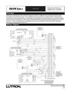
WIRING. Home Run Wiring of. GRAFIK Eye Controls. APPLICATION NOTE W2. 8
/98. Overview. Wiring Diagram. GRAFIK Eye 3000 Series Control Unit and ...
shown in the wiring diagram. 2. Connector indications. • Female connectors are
shown as a box constructed of a single continuous line. Male connectors are ...
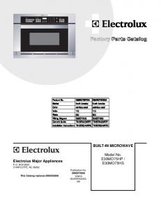
BUILT-IN MICROWAVE. Model No. ... 5304461114 A B Thermal Cut-Out,
convection/oven, (2). 7 .... 5304480616 A B Power Board, printed circuit. 141#.
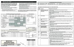
spaced away from all metal parts and panels. • All safety ... Test keyboard circuits
using test matrix. Replace touch panel if defective. 4. If keyboard ciruits check ...
MICROWAVE OVEN TECH SHEET. CAUTION. Disconnect from Electrical Supply
Before Servicing Unit. PRECAUTIONS TO BE OBSERVED BEFORE AND.
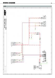
34. Wiring diagram. Audi A4. 2.8I - Injection Engine, 6—Cylinder, Code AHA.
1998 m. y. ... Washer Intermittent Relay e Wipper / Washer lnterrnlttent Relay. 08/
97. W425502062l. Edition ... Central Locking / Alarm System / interior Light Delay
.
Dec 4, 2014 ... MAzDA 2. 2011-2014 retains steering wheel controls and adds gauges. NOTICE:
Automotive Data Solutions Inc. (ADS) recommends having ...
Sep 23, 2014 ... iDatalink Maestro RR Radio Replacement Interface ... nissan 370 Base 2009-
2013 ... Wiring Diagram. 3 ...... nissan sentra Base 2007-2012.
How to use the circuit diagrams 3. Fuses. location on the vehicle 4 Group 59. Anti
-lock Brake System. Relays. location on the vehicle 5 ABS. Wiring harnesses ...
Dec 17, 2014 ... in are the properties of their respective owners. .... honda accord 2008-2009.
Automotive Data Solutions .... honda accord crosstour 2010-2012.
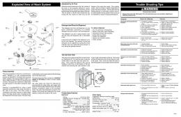
Trouble Shooting Tips. Exploded View of Wash System. Tub and Door Seal. The
door seal is pressed into the tub channel for an interference fit. To install the ...
WIRING DIAGRAMS AND SERVICE. INFORMATION ENCLOSED. REPLACE
CONTENTS IN BAG. NOTICE - This service data sheet is intended for use by
persons ... Circuit Analysis Matrix ... 4. If keyboard ciruits check good replace the
EOC.
WIRING DIAGRAMS AND SERVICE INFORMATION ENCLOSED. REPLACE
CONTENTS .... Power Supply Board (PS1 or PS2) Test Points. Connector P1 pins
1 ...
to boom mic*. New Power. Cable. Existing Audio/. Mic cable. 9V+. (—). (—) audio
+. Two. Grounds. Merge. Crossover Cable. Left. Volume Control to boom mic*.
Wiring cable numbers are on pages l thru 5. Figure NO_ ' R1 v A t l A 'oltmeter to
me er _ 10/74 ' if;. T-700 Cummins Alternator 2 ~. - T-sooi"? Cummins Alternator ...
To connect the Circuit to your microcontroller, follow the diagram below. • Make
sure your Circuit and microcontroller share a common ground. Microcontroller.
If you remove a connector, double over the wire before installing it ... Instrument
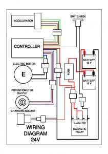
Wiring Diagram ... Win/Gm" 24v Back Light 24 Voit Bus (God for a 12v system).
87. 30. CHARGING SOCKET. SWITCHBOX. ACCELERATOR. E. ELECTRIC
MOTOR. POTENTIOMETER. OUTPUT. BATTERY. 12 V. BATTERY. 12 V.
WIRING.
Wiring diagram. Fuse holder. 9-Pin Relay Carrier in the instrument panel ..... 98.
97--53373. 1. E. 23. E. 2/XR. 15/30. 17/58d. 1/XZ. 14/58. 10/31. 7/A. 8/NL. 3/TFL.
WIRING V. 165 MODEL 12. Voltage regulator - 2 Red wires, green, yellow,.
WIRING DIAGRAM KEY black wire,. 13. Circuit breaker terminal - Black wire.
To ensure proper installation of your GEM Controller, use GEM's directions in lieu
.... A replacement transmitter or a spare can be bought online, loss of range or ...