Closed Loop Control of Soft Switched Forward Converter Using Intelligent Controller
1
IJCTA, 9(33), 2016, pp. 01-10 © International Science Press
A Cost Effective Speed Control Method for BLDC Motor Drive M. Arun Noyal Doss* V. Kalyanasundaram* V. Ganapathy** and K. Karthik***
Abstract : This paper presents a cost effective speed control method for brushless dc (BLDC) motor drive using PI controller. Pulse width modulation (PWM) technique is used which is the most widely used speed control technique. The switches in voltage source inverter (VSI) are electronically commutated using PI controller feedback signal. The switches are operated at low frequency to minimize the switching losses. Simulation of the proposed topology is performed using Matlab and the obtained results validate the efficiency of the system. Keywords : Brushless DC(BLDC) motor, Pulse width modulation (PWM) technique, Voltage source inverter (VSI), PI controller, electronic commutation, hall-effect, Matlab.
1. NOMENCLATURE BLDC PWM VSI G(s) kp ki J B
– – – – – – – –
Brushless DC motor Pulse width modulation Voltage source inverter System transfer function Propotional gain Integral gain moment of inertia Coefficient of friction
2. INTRODUCTION The speed control techniques for variable speed drives have changed rapidly nowadays when compared to the conventional prototypes. With the advancement in the power electronics field advanced controllers and converters are designed for both AC and DC drives. Some of the popular controllers like PI, PID, Fuzzy logic, Genetic algorithm etc are being used in industrial applications for controlling power converters. Further several PWM techniques were also developed to improve the switching performance and reduce switching loss in power electronic converters. Since the conventional speed control methods are not highly efficient, designing a suitable speed controller for a particular motor has been a primary concern for the present day researches. Among all the motors available, BLDC motor has been chosen for this paper for their advanced sophisticated features. * ** ***
Assistant Professor, Department of Electrical and Electronics Engineering, SRM University, Kattankulathur, 603203, India,
[email protected],
[email protected]. Professor, Department of Information Technology, SRM University, Kattankulathur, 603203, India,
[email protected]. PG Scholar, Department of Electrical and Electronics Engineering, SRM University, Kattankulathur , 603203, India
[email protected].
2
M. Arun Noyal Doss, V. Kalyanasundaram, V. Ganapathy and K. Karthik
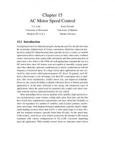
Brushless dc (BLDC) motor is a type of permanent magnet synchronous motor which is widely used nowadays due to the advantages like high power density, high efficiency, low maintenance requirement, and their tolerance to electromagnetic interference (EMI) problems. These motors can be operated at a wide range of speed. Fig.1 shows the conventional BLDC drive topology. (Figure.1)
Figure 1: Conventional BLDC drive topology
The main difference between BLDC motor and permanent magnet synchronous motor is that BLDC motor have trapezoidal back emf. Unlike synchronous motors BLDC motors are self starting in nature and speed can be varied smoothly. The BLDC motor has torque speed characteristics similar to a DC motor. BLDC motor looks similar to that of a DC motor. In DC motors, the stator may contain permanent magnet if it is a Permanent Magnet dc (PMDC) motor. The rotor will have windings and windings will get excited using commutator and brushes arrangement. On the other hand the BLDC motor will have windings in the stator and the permanent magnets are present in the rotor. The term brushless is mentioned because here the brushes and current carrying coils are replaced by permanent magnets and the permanent magnets perform the rotator operation. Traditionally Ferrite magnets are used for making permanent magnets in rotor and nowadays rare earth magnets are gaining popularity because of their high magnetic field density per volume. Normally BLDC motors are not directly connected to three phase AC supply system. The phase windings of the BLDC motor are energized using a three phase inverter. Since BLDC motors are inverter driven the speed of the motor is controlled by varying the DC link capacitor voltage on the source side of the inverter or by varying the pulse width of the inverter switching pulses. But the speed cannot be controlled over a wide range using PWM technique. Further the inverter switches are subjected to large voltage stress which will decrease the life time of power electronic components. Prior researches have been made in establishing speed control and toque control for BLDC motor. Analysis on brushless machines and their applications have been stated in1. Torque control of BLDC drives using direct torque control method is explained in 2. The method for minimizing commutation torque ripple during the implementation of direct torque control is explained in3. 4explain the indirect flux control method in BLDC motor. Self control of BLDC motor using a three dimensional co-ordinate system is explained in 5. Direct torque control of BLDC motor using self controlled flux linkage is explained in 6 and in 7 direct torque control along with along with non ideal back emf is explained. An approach to torque ripple reduction using direct torque control is explained in [8]. But the speed and torque control approach based on direct torque control approach mentioned o in 6,7,8 requires complicated control algorithms and thus increased the cost and size of the system. Analysis on sensor based speed control method for BLDC motor is explained in 9. Performance analysis of PI controller based BLDC motors is explained in 10.
A cost effective speed control method for BLDC Motor Drive
3
The method to minimize cogging torque by reducing the stator tooth width is presented in 11. In this paper the cogging torque is minimized using bifurcated stator teeth and the modification of stator teeth is made using finite element analysis. In 12 a mathematical model of a BLDC motor has been proposed to minimize cogging torque, harmonics and torque ripples.13 explains a speed control model for a BLDC motor designed and analyzed using PSIM. A comparative analysis on various controllers used to improve the transient response in speed and torque ripple minimization in BLDC motor.15,16,17 explains the basic principle of BLDC motor, operating principle of various power electronic converters and drive systems. This paper proposes a PI controller based approach for controlling the switching pulses of the inverter and thereby controlling the speed of the motor. The parameters considered for analyzing the BLDC motor is mentioned in table.1 Table 1 Specifications of BLDC motor Parameters
Value
Connection type
Star
Rated Current
4.52 A
Rated Voltage
310 Vdc
Rated Speed
4600 rpm
Electromechanical torque
2.2 Nm
To employ a cost effective speed control mechanism PI controller is used. In the PI controller two control strategies are implemented namely, proportional control and the integral control. The proportional control produces an error signal that is proportional to the current error value. The value of the error can be adjusted by multiplying with the proportional gain value (kp). The integral control produces an error value which is proportional to the magnitude of the error and duration of the error. The value of the corresponding error can be adjusted by multiplying with the integral gain value (ki). The theoretical analysis is performed by considering the parameters mentioned in Table.1.
3. MATHEMATICAL MODELLING OF BLDC MOTOR The voltage equation of the BLDC motor is given as, dia di d + M ab b + M ac ic + ea dt dt dt di di d Vb = ib R b + Lb b + M ba a + M bc ic + eb dt dt dt di di di Vc = ic R c + Lc c + M ca a + M cb b + ec dt dt dt Va = ia R a + L a
Here ea, eb, ec are the back emf of BLDC motor.1 The mathematical model of BLDC motor can be expressed in matrix form as, é Va ù é R a 0 é L a M ab M ac ù éia ù 0 ù éia ù é ea ù ê ú ê úê ú ê ú ê úd ê ú ê M ba Lb M bc ú êib ú = ê Vb ú - ê 0 R b 0 ú êib ú - ê eb ú ê ú dt ê ú ê ú ê úê ú ê ú êM ú êi ú êV ú ê 0 ú ê ú êe ú M L 0 R cb c û c û ë ic û ë ca ë cû ë cû ë ë cû
(1) (2) (3)
(4)
Where La, Lb and Lc are self inductance and Mab, Mba, Mbc, Mcb, Mac and Mca are mutual inductance. For simplification all self inductance are assumed as Land all mutual inductance are assumed as M. Since it is a balanced three phase system all resistance are equal and therefore, Ra = Rb = Rc = R
(5)
4
M. Arun Noyal Doss, V. Kalyanasundaram, V. Ganapathy and K. Karthik
Replacing the value of self inductance, mutual inductance and three phase resistance, eq.4 can be written as, éL ê êM ê êM ë
M L M
M M L
é Va ù é R ù éia ù ê ú ê úd ê ú ú êib ú = ê Vb ú – ê 0 ê ú ê ú dt ê ú êV ú ê 0 ú êi ú ë cû ë û ë cû
0 R 0
0 0 R
ù éia ù é ea ù úê ú ê ú ú êib ú – ê eb ú úê ú ê ú ú êi ú ê e ú ûë cû ë cû
(6)
The electromagnetic torque of the BLDC motor is expressed as, d + B + Tl Te = J dt In terms of angular velocity, the electromagnetic torque of BLDC motor is expressed as, 1 (ea ia + ebib + ecic ) Te = The transfer function of BLDC motor is, 1 ke G(s) = 2 Tm Te s + Tm s + 1
(7)
(8)
(9)
Where Tm and Te are the mechanical time constant and electrical time constant respectively.
4. PROPOSED PI CONTROLLER BASED SPEED CONTROL SYSTEM The proposed drive system has a three phase inverter driven BLDC motor powered by a Single phase AC supply connected to a single phase bridge rectifier. The speed of the BLDC motor is sensed using a rotor position sensor and the using a comparator the measured speed is compared with a reference speed. The error signal is given as input to the PI controller by comparing actual speed and reference speed. The output of PI controller is fed as input to current limiter and this signal will be considered as the reference current signal. This reference current signal is compared with actual current signal which is obtained from line current feedback. A current sensor is used to measure the line current. The output of the P controller is compared with a triangular wave and by varying the duty cycle corresponding switching pulse is given to the inverter. Fig. 2 shows the schematic layout of the proposed closed loop speed control system. (Figure.2)
BLCD Motor
Figure 2: Schematic layout of proposed topology
The calculation of proportional gain (kp) and integral gain (ki) is done using Ziegler-Nichols method.
A cost effective speed control method for BLDC Motor Drive
5
5. PI CONTROLLER DESIGN PI controller is the most widely used feedback control system in industries. Basically the control method has two feedback components namely proportional gain (kp) and integral gain (ki). The PI tuning method is performed for the speed control and corresponding parameters are obtained. Since the mathematical model of the system is complicated the control parameters are tuned using Ziegler-Nichols method. The controller parameters are obtained from the output response using the following response graph. (Figure 3) c(t)
Tangent line at infection point
K
t
0
L
T Figure 3: Ziegler-Nichols rules for tuning P, PI and PID controller
The response of the system is obtained and the point of inflation is noted. A tangent line is drawn on the point and the values of L and T are calculated. The value of K is taken from the point when the system reaches a stable condition. Table.2 shows the formulas for calculating Kp, Ki and Kd for P, PI and PID controller. The PI controller basically works in two modes namely the proportional mode and the integral mode. The proportional mode controls the instant speed error and the integral mode determines the reaction based on the recent error. The output of the PI controller is given by, t
Output(t) = k p e(t ) + ki ò e()d
(10)
0
Where e(t) is the error signal. The error signal e(t) e(t) = ref – m(t)
Is calculated by,
(11)
Where ref is the reference speed and m(t) is the measured speed. Table 2 Result of PI tuning method Type of Controller
kp
ki
kd
P
T/L
∞
0
PI
0.9T/L
L/0.3
0
PID
1.2T/L
2L
0.5L
6
M. Arun Noyal Doss, V. Kalyanasundaram, V. Ganapathy and K. Karthik
Table.3 shows the calculated values of kp and ki obtained for the proposed system. Table 3 Result of PI tuning method Method
ki
kp
Overshoot(%)
Drop in speed (rad/sec)
Settling time (Sec)
Ziegler-Nichols method
16.61
0.013
2.7
6.5
0.20
The simulation is performed by considering reference speed as 3000 rpm. The PI controller based speed control model is given by ki + kp G(s) = (12) s Where, G(s) = Controller transfer function, kp = Proportional gain, ki = Integral gain. These parameters are calculated using Ziegler-Nichols method. The closed loop transfer function of the system is shown in Figure. 4.
Figure 4: Closed loop transfer function of PI controller
The system transfer function equation is, T(s) =
(k p s + ki )/J
2
(13)
kp = 2ξn J – B ki = Jn
(14) (15)
s + {(B + k p ) s + k } /J
Here kp and ki values are given by,
6. SIMULATION RESULTS A. Dynamic Performance of the proposed Drive Table 4 Comparison of Speed and Torque at different Voltage levels. Voltage
Speed
Torque
12
205
3.63
24
405
1.84
36
618
1.20.
48
859
0.868
60
1048
0.711
72
1208
0.617
A cost effective speed control method for BLDC Motor Drive
7
Test simulations prove the efficiency of the proposed drive system. The BLDC motor is capable of operating in between 12V to 310V. The speed and torque of the motor recorded at different voltages are mentioned in table.4. By choosing the values of kp and ki as mentioned in table.3 the peek overshoot % was 2.7. The motor was able to reach 1400 rpm at 80V. Fig.5 shows the speed torque response of the proposed drive system. (Figure.5) 4
Speed Vs Torque
3.5
Torque(N-m )
3
2.5
2
1.5
1 0.5 200
400
600
800 Speed (RPM)
100
1200
1400
Figure 5: Speed vs Torque response of BLDC motor
The motor was able to achieve a maximum speed of 3000 rpm during test simulation. Figure.6 shows output speed of the BLDC motor. (Figure.6)
Figure 6: Speed of BLDC motor
Figure.7 shows the line currents of the voltage source inverter. (Figure.7)
8
M. Arun Noyal Doss, V. Kalyanasundaram, V. Ganapathy and K. Karthik
Figure 7: Line current of voltage source inverter Vab 500 400 300
Voltage (V)
200 100 0 –100 –200 –300 –400 –500
0
0.005
0.01
0.015
0.02
0.025
0.03
0.035
0.04
0.045
0.05
0.03
0.035
0.04
0.045
0.05
0.03
0.035
0.04
0.045
0.05
Time(s) Vbc 500 400 300
Voltage (V)
200 100 0 –100 –200 –300 –400 –500 0
0.005
0.01
0.015
0.02
0.025 Time(s) Vca
500 400
Voltage (V)
300 200 100 0 –100 –200 –300 –400 –500
0
0.005
0.01
0.015
0.02
0.025 Time(s)
Figure 8: Line voltage of voltage source inverter
A cost effective speed control method for BLDC Motor Drive
9
The motor consumed a line current of 1.2A and the line voltage was 265V. Figure.8 shows the line to line voltages of voltage source inverter. (Figure.8) B. Hardware Implementation of the proposed topology The PI control algorithm is programmed using dsPIC30f2010 digital signal controller. The BLDC motor with the specifications mentioned in table.1 is considered for the evaluation of the hardware prototype. Figure.9 shows the hardware prototype of the proposed topology. (Figure.9)
Figure 9: Hardware Prototype of the proposed topology
The performance of the BLDC motor was smooth and the motor was operated at 1508 rpm. Figure.10 shows the speed of the BLDC motor. (Figure.10)
Figure 10: Speed of the BLDC motor at 1508 rpm
7. CONCLUSION This paper has proposed a cost effective speed control method for BLDC motor drive using PI controller. The motor is operated in a wide range of speed. The results obtained from matlab/simulink simulation have proved the effectiveness of the implementation of PI controller. But even though a PI controller finds good application in industrial drives speed control is less accurate. Because during starting oscillations occur in speed which damps out in time. PI controller holds good only for linear systems and small variations in speed can be observed. The effectiveness of the proposed topology can be further improved by using neural-fuzzy logic technique.
8. REFERENCES 1. Takashi Kenjo and Shigenobu Nagamori.Brushless motors: advanced theory and modern applications,Tokyo, Japan: Sogo Electronics Press, 2003. 2. Liu Yong, Zhu Z Q and Howe D. Direct Torque control of brushless DC drives with reduced torque ripple. IEEE Trans. On Industry Applications, vol.41, no. 2, pp. 599-608, 2005.
10
M. Arun Noyal Doss, V. Kalyanasundaram, V. Ganapathy and K. Karthik 3. Liu Yong, Zhu Z Q and Howe D. Commutation torque-ripple minimization in direct-torque-controlled PM brushless DC drives. IEEE Trans. On Industry Applications, vol. 43, no. 4, pp. 1012-1021, 2007. 4. Ozturk S.B., and Toliyat H.A Direct Torque and Indirect Flux Control of Brushless DC Motor. IEEE Trans. on Mechatonics, vol. 16, no. 2, pp. 351-360,2011. 5. Gao Jin and Hu Yuwen. Direct self-control for BLDC motor drives based on three-dimensional coordinate system. IEEE Trans. on Industrial Electronics, vol.57, no. 8, pp. 2836-2844, 2010. 6. An Quntao, Sun Lizhi, Liu Chao and Sun Li. Flux linkage self-control based direct torque control of brushless DC motor. Proceedings of the CSEE, vol. 30, no. 12, pp. 86-92, 2010. 7. Seog-Joo Kang and Seung-Ki Sul. Direct torque control of brushless DC motor with nonideal trapezoidal back EMF. IEEE Trans on Power Electronics, vol. 10, no. 6, pp. 796-802, 1995. 8. Zhenguo Li, Lu Wang, Songfa Zhang, Chunjiang Zhang, and Jin-Woo Ahn. Torque Ripple Reduction in Direct Torque Controlled Brushless DC Motor. ICEMS2011, 2011. 9. Ms. Juli Singh. Analysis of Speed control of BLDC motor drive using sensors International Journal of Engineering Research Applications (IJERA) , Vol 2, Jun2012. 10. Vinod KR Singh Patel and A.K Pandey. Modeling and Performance Analysis of PID controlled BLDC motors and different schemes of PWM controlled BLDC motors. International Journal of Scientific and Research Publications,Vol 3,April 2013. 11. Mohammed Rizwan and ArunNoyalDoss.M . Reduction of Cogging Torque in PMBLDC Motor With Reduced Stator Tooth Width and Bifurcated Surface Area Using Finite Element Analysis.First international conference on Electrical Energy Systems (ICEES),Page: 128 – 132,Jan-2011. 12. M. ArunNoyal Doss, V.Ganapathy, V.Marthandan, D.Mahesh. Modelling and Simulation of BLDC motor for minimizing Cogging torque, Harmonics and Torque ripples. International review on modelling and simulations. Vol.6, N.5, October 2013. 13. G.Ranjith Kumar, M.ArunNoyal Doss, K.N.V. Prasad and K.C.Jayashankar. Modelling and Speed control of Permanent magnet synchronous motor at constant load torque using PSIM. International conference on sustainable energy and intelligent system,SEISCON-2011. 14. G.Ranjith Kumar, K.N.V.Prasad, M.ArunNoyal Doss. Improve the Transient Response of Speed and Torque Ripple minimization of the BLDC motor by various controllers. 15. R.Krishnan. Electric Motor Drives”,Modelling,Analysis and Control. 16. Gopal K.Dubey. Power Semiconductor Controlled Drives. 17. Bimal Bose. Power Electronics and Motor drives Advances and Trends.