IEEE TRANSACTIONS ON NEURAL SYSTEMS AND REHABILITATION ENGINEERING, VOL. 22, NO. 5, SEPTEMBER 2014
937
A Device for Emulating Cuff Recordings of Action Potentials Propagating Along Peripheral Nerves Robert Rieger, Senior Member, IEEE, Martin Schuettler, Member, IEEE, and Sheng-Chih Chuang
Abstract—This paper describes a device that emulates propagation of action potentials along a peripheral nerve, suitable for reproducible testing of bio-potential recording systems using nerve cuff electrodes. The system is a microcontroller-based stand-alone instrument which uses established nerve and electrode models to represent neural activity of real nerves recorded with a nerve cuff interface, taking into consideration electrode impedance, voltages picked up by the electrodes, and action potential propagation characteristics. The system emulates different scenarios including compound action potentials with selectable propagation velocities and naturally occurring nerve traffic from different velocity fiber populations. Measured results from a prototype implementation are reported and compared with in vitro recordings from Xenopus Laevis frog sciatic nerve, demonstrating that the electrophysiological setting is represented to a satisfactory degree, useful for the development, optimization and characterization of future recording systems. Index Terms—Cuff electrode recording, device testing instrument, electroneurogram (ENG) emulator, microcontroller, nerve recording, propagation velocity.
I. INTRODUCTION
T
HE recording, processing and subsequent interpretation of naturally occurring neural signals [electroneurogram (ENG)] using advanced circuits and systems is a major objective in current neuroprosthetics research [1]–[6]. Neural signals generated by natural sensors within the body can be used to obtain information such as skin contact, force or limb position, which may be employed as feedback signals in prosthetic systems [2], [3], [6]. The evaluation of these acquisition front ends requires considerable effort since the signals to be obtained are very small (in the micro- to millivolt range), many parallel recording channels are required for certain approaches (e.g., for velocity discrimination as in [1] and [7]), and interfacing to a live neuron is a particularly delicate procedure. For chronic peripheral recording, implanted nerve cuff electrodes are the most well-established extraneural interfaces [8].
Manuscript received July 08, 2013; revised December 03, 2013; accepted January 12, 2014. Date of publication January 16, 2014; date of current version September 04, 2014. This work was supported in part by the Taiwan National Science Council under Grant NSC 102-2221-E-110-007-MY2. R. Rieger and S.-C. Chuang are with the Electrical Engineering Department of National Sun Yat-Sen University, 804 Kaohsiung, Taiwan (e-mail:
[email protected]). M. Schuettler is with the Laboratory for Biomedical Microtechnology, Department of Microsystems Engineering-IMTEK, University of Freiburg, Germany. Color versions of one or more of the figures in this paper are available online at http://ieeexplore.ieee.org. Digital Object Identifier 10.1109/TNSRE.2014.2300933
Fig. 1. Typical setup for conventional in vitro nerve recording using explanted nerve. Proposed emulator replaces the components shown above the dashed line. DUT is device under test.
The electrode cuff is wrapped around the nerve, so that local currents associated with a propagating nerve signal [action potential (AP)] travel through the insulating cuff and the resulting potential differences between embedded ring electrodes are recorded. Variants of the common circular electrode have been used for both recording and stimulation of nerve [9], [10]. Dividing the ring electrodes into a number of smaller contact areas (contact matrix) was studied to increase the recording selectivity by acquiring signals predominantly from fibers closer to the contact site. Another modification, the flat interface nerve electrode design (FINE), flattens the lumen of the cuff to shape the nerve into a geometry which helps localize the recording volume. The longitudinal intrafascicular electrode (LIFE) is an example of a linear electrode array for intraneural deployment. The LIFE electrode contacts are spaced along a flat nonconductive carrier which is inserted into the perineurium. Since the LIFE does not surround the nerve and electrode areas are small, recorded AP amplitude and dynamics are fairly dependent on the positioning of the LIFE with respect to the nerve axis [11]. In this paper we describe an emulator of peripheral nerve which is used for testing advanced recording setups, our central interest being the evaluation of velocity selective recording (VSR) systems [1], [7]. VSR requires the parallel recording from multiple adjacent electrodes within a multi-electrode recording cuff (MEC) employing ring electrodes. Subsequent signal processing then allows the classification of nerve traffic according to AP velocity [6], [12]. More generally, for the testing and evaluation of actual hardware implementations of nerve recording arrangements, in vitro experiments are required which necessitate the explantation of nerve, artificial selective nerve stimulation and a complex recording setup. Fig. 1 shows a typical arrangement for stimulation and simultaneous recording from a nerve, where the nerve is immersed in a saline bath
1534-4320 © 2014 IEEE. Personal use is permitted, but republication/redistribution requires IEEE permission. See http://www.ieee.org/publications_standards/publications/rights/index.html for more information.
938
IEEE TRANSACTIONS ON NEURAL SYSTEMS AND REHABILITATION ENGINEERING, VOL. 22, NO. 5, SEPTEMBER 2014
TABLE I COMPARISON WITH DIFFERENT APPROACHES ENG TEST SIGNAL GENERATION
FOR
Fig. 2. Equivalent circuit model of a section of nerve embedded in a multielectrode cuff with the cuff outline shown for illustration. Low resistance tissue outside the cuff is approximated as a short circuit between the nodes 0 and . correspond to the time delay in (4). Indices of the sources
(see [1], [16], and [17] for recording examples). Since faster fibers within the axon bundle are activated by weaker stimuli compared to slower fibers, a recruitment order exists which prevents selective stimulation of only slow fibers. Applying a sinusoidal high-frequency waveform to an additional cuff allows blocking the propagation of action potentials in larger fibers, hence allowing selective conduction of slower APs [18]. Measurements using this kind of setup are difficult to attain as a suitable nerve must be obtained, the immersing solution should match the properties of body fluid (the temperature and acidity must be controlled), the nerve must not be damaged during setup, etc. The procedure is therefore time consuming, expensive, prone to error and usually involves a set of initial animal experiments which do not deliver useful data. The setup described in this paper emulates the electrical properties of a nerve and provides an interface to the circuit under test. Notably the system is not intended to replicate detailed physical properties of nerve and electrode or nerve functional characteristics. A higher level of abstraction is proposed here. The nerve traffic is characterized by its velocity distribution and by the amplitude observed at the electrode site. The system is representative of a typical nerve in terms of load resistances, electrode voltages and AP propagation characteristics as conventionally measured from a cuff electrode. The emulator is not intended for testing new electrode designs but it is used for evaluating the acquisition and processing stages. Although the emulator may therefore not eliminate the need for final in vitro assessment of a novel hardware, it is expected that it reduces the number of initial inconclusive animal experiments during circuit tuning, design optimization and characterization. The simplified equivalent circuit of a section of nerve embedded within an insulating cuff is shown in Fig. 2. The local , membrane potential is represented by voltage sources and and are extracellular and axonal sectional resistances, respectively [12]. Various simulation studies have been carried out in the recent past to estimate the performance expected from nerve recording setups and which established that the 1-D nerve model is of sufficient accuracy for many practical applications [12], [14], [15]. The model assumes that the internode is not leaking and that therefore the voltage gradients within the cuff are linear. Moreover, the tissue outside the cuff is presumed
to be of low resistance compared to , so that both end voltages of the cuff are approximated as remote reference ground. Most of the recorded signal power is contained in a bandwidth between about 300 Hz–5 kHz [13]. Membrane capacitance is neglected in this model as the voltage sources define the AP shape and propagation characteristics, eliminating the need of a physical capacitance to determine the AP dynamic properties. The dynamic behavior is controlled by a microcontroller which emulates the electrode voltages of travelling APs, the interface consists of resistors and capacitors. The controller yields different scenarios which can be selected by the user. This includes provision of compound APs following stimulation (CAP) and naturally occurring nerve traffic of differing selectable velocity bands. The proposed emulator thus replaces the nerve, activation and blocking cuffs, activation and blocking stimulators, saline bath and trigger amplifier of a conventional in vitro setup during initial testing. Table I provides a comparison with other reported approaches for ENG test signal generation. The electronic emulator yields especially low setup complexity and a wide range of reproducible test scenarios. The prototype presented here is the further development of a system we reported in [19]. The previous system consisted of a series of microcontrollers, where each controller generated two channels of digital AP waveforms. The number of electrode channels could be expanded by adding further controllers to the system. The computing power hence increased proportionally with the number of channels, enabling this system to generate propagating APs in real-time. This trades off with a higher hardware complexity due to the large number of routing tracks connecting multiple controllers to the digital-to-analog converter (DAC) chips which provide the analog signal outputs. In the present system we limit the channel count to eight channels with a sampling rate of 190 kHz per channel. This allows operating the system with a single microcontroller for signal generation (a second controller is used to monitor user input) and the use of multiplexing DACs. The speed limitation is imposed by the time it takes the microcontroller to place a new sample on the digital output port. The design of the emulator is further described
RIEGER et al.: DEVICE FOR EMULATING CUFF RECORDINGS OF ACTION POTENTIALS PROPAGATING
Fig. 3. Principle block diagram of the proposed emulator. Axon Microcontroller generates digital waveforms which are converted into eight voltage output channels using two discrete quadruple-DACs preceding the resistive attenuation interface.
in Section II. Measured results from a prototype hardware implementation and comparison with in vitro recordings are presented in Section III, followed by discussion and conclusions in Section IV.
939
Fig. 4. DAC voltages are attenuated using resistive dividers . Emu. Access points have resistance representative lated electrode voltages are models electrode access resistance. of the cuff-nerve interface. Resistance and provide low-pass filtering.
is chosen to yield a resistance similar to the resistance at the recording point in the axon model of Fig. 2. Analysis of this model yields for the resistance at node (with respect to remote ground) (1)
II. AXON EMULATOR IMPLEMENTATION A. Hardware Design The proposed emulator block diagram is shown in Fig. 3. It is designed around the Axon Microcontroller (AM) using a PIC18F4520 device (Microchip, [20]) which synthesizes eight channels of digital AP waveforms according to user input and provides the timed signals via two 8-bit digital output ports. The processor is operated at its maximum speed of instruction cycles per second (10 MIPS). Each digital port connects to a quad-multiplexed DAC (AD7305, Analog Devices [21]) to generate the analog outputs. Eight synchronized parallel analog channels are thus available. The voltage signals represent the potential measured locally at the electrode sites within the cuff with respect to a remote reference (monopolar recording). Differential floating voltage output DAC could be used to directly realize the transmembrane AP (TMAP) voltage sources in the model of Fig. 2. However, truly floating output DAC with appropriately small output resistance are uncommon and so more conventional single-ended output DAC are used for the implementation described here. The DAC has an operating voltage range of 3–5 V, compatible with the microcontrollers. It also provides an 8-bit parallel data interface which enables loading a new waveform value from the AM into the DAC using a single pair of operating instructions. Moreover, the DAC internal sample-and-hold (S/H) function updates all output lines synchronously, which avoids any time skew between the channels. The maximum output voltage of the DAC is determined by a reference signal which is set to 1 V. Using single-ended DAC requires synthesizing the electrode AP voltages from the TMAP signals in software and providing the resulting monopolar electrode voltages on the output lines. The monopolar voltage amplitude is in the microvolt range, considerably smaller than what can be generated reliably by the DAC. Therefore, resistive dividers are used to attenuate the DAC output signal. Fig. 4 shows this resistive interface with and working as potential dividers. The attenuated output voltage is available at the recording points . Resistor
is the number of electrodes and the approximation where holds for the typical case when . For our implementation and so ranges between and . For simplicity, a constant resistance of 825 is selected for , which is on the order of magnitude of the axonal resistance between a pair of cuff recording electrodes [22]. As a simple approximation of cuff electrode capacitance, capacitors (about 100–400 nF, [7]) can optionally be added in parallel with resistors . is chosen to be 1 , yielding an attenuation of about 1:1,200. The DAC output signal is scaled up accordingly. Additional series resistors are added to represent contact and lead resistance. A value of 1 is chosen for these devices. Note that selecting a large does not significantly increase the thermal noise at the recording node as the noise power is proportional to the small resistance of the parallel connection of and . Devices and are added to yield a low-pass filter which smooths the quantization steps of the DAC output signal. Since an exact cutoff frequency is not essential, convenient values are chosen. Measurement revealed that using 1 and 2.2 nF components (resulting in a cutoff at 72 kHz and attenuation of about 1/3 at the DAC update frequency) yields visually satisfying quantization artifact suppression. A User Microcontroller (UM, PIC18F2520 [20]) is incorporated into the system which continuously monitors the user control inputs. In this implementation, the user can select different scenarios via hardware switches. Furthermore, AP velocities can be set via three potentiometers which are read out using the ADC of the UM. The UM communicates with the AM via a serial digital interface (SPI). Partitioning the system in this way provides several advantages. Since only the dataframe with instructions is passed to the AM (see Fig. 3), different modes of user input (switches, dials, etc.) can be accommodated conveniently by reprogramming only the UM. Additional parameters can be passed via the SPI to flexibly adjust the emulated electrode positions and cuff length. The UM can also be replaced by a more advanced interface in a future extension of the system since the timing of the AP generation is not affected by the type
940
IEEE TRANSACTIONS ON NEURAL SYSTEMS AND REHABILITATION ENGINEERING, VOL. 22, NO. 5, SEPTEMBER 2014
of interface implementation. Currently, the following three distinct scenarios are selectable via the user controls. 1) Compound AP generation (CAP). In this mode of operation, traveling APs are generated repeatedly following an artificially generated stimulus pulse. Velocities for up to three groups of AP can be set via the potentiometers within a range of 10–150 m/s. 2) Natural Nerve Traffic from a low-velocity population. A large number of unsynchronized APs of random velocities are superimposed (50 APs in this implementation). This mode represents naturally occurring nerve traffic. The range of velocities is set to 10–50 m/s. 3) Natural Nerve Traffic from a high-velocity population. The range of velocities in this scenario is set to 50–100 m/s. The natural traffic scenarios will be used for initial characterization of the spike sorting capabilities of the system under test. An overview of prominent sorting algorithms is given in [7], [23], and [24], with VSR being the target algorithm for this study. Furthermore, two test amplifiers each with a gain of 61 dB and 100 kHz bandwidth are added to the printed circuit board (PCB) containing the system for convenient probing of the small electrode voltages during evaluation. B. AP Synthesis The emulated nerve traffic is synthesized from elementary TMAP waveforms. A relatively simple analytical approximation for the TMAP voltage is the alpha function introduced by Rall [25] for modeling synaptic transient behavior
with
(2)
where and are fitting parameters (units of Vs and s , respectively) and is the time vector. We normalize the amplitude of and use it as a template with a fixed spike duration, where the peak occurs at time s. Using this parameter value the template approximates the timing obtained using physiological parameters published for Xenopus Laevis frog nerve measured at a temperature of 20 C [26] and then adjusting to 22 C by simulation in the NEURON software environment [27]. The template function is further smoothed using a first-order low-pass filter (10 kHz cutoff). This avoids operating with a discontinuous derivative at the transition point , which might otherwise result in noticeable artifacts when differential signals are formed. The amplitude is subsequently quantized to 8-bit resolution (Fig. 5) and stored in the AM nonvolatile memory. An AP is generated by reading successive samples from the stored template and scaling their amplitude. As a result of velocity related nerve geometry and associated variation in axonal resistance, the AP amplitude recorded by a cuff depends on propagation velocity . For many practical recording situations there is an approximately proportional relation between recorded amplitude and velocity [15]. Thus, APs travelling with higher speed exhibit larger amplitude than slower APs. To express this proportionality we let the scaling factor be a func-
Fig. 5. TMAP template function consisting of 320 samples. It was obtained by low-pass filtering, quantizing and scaling (2) to full 8-bit amplitude range.
tion of velocity. A practical function for this system is found by trial as
(3) where parameter is set to 7 m/s (limiting the practical minimum velocity to about 10 m/s). The values were chosen to yield a waveform which matches well with actual in vitro nerve recordings as provided in Section III and with results from the literature [26]. Propagation of the TMAP along the axon is realized by introducing a time-delay between the waveforms generated at adjacent electrodes, modeling the delay that the amplifiers in a MEC record due to the time an AP requires to travel from the stimulation point to the respective electrode. The voltage measured using a monopolar configuration is a superposition of the individual TMAP voltage sources. Analysis of the circuit model of Fig. 2 yields for the potential obtained at electrode
(4) where denotes the distance along the nerve between a node and the stimulation site. The expression is modified from the 1-D model derived by Struijk in [15] by normalizing the amplitude coefficient of the last term to unity (since is scaled to obtain the desired AP amplitude) and by introducing an additional time delay to account for AP propagation delay between the stimulation and first recording point. This delay is inherently given by measuring the electrode distance with respect to the stimulation site and dividing by the propagation velocity in terms , and , respectively. Up to three scaled TMAP templates (one for each emulated velocity group) are calculated and summed by the AM for each electrode channel. C. Software Design The waveforms for the CAP scenario are synthesized by the AM when the appropriate command is received via the SPI.
RIEGER et al.: DEVICE FOR EMULATING CUFF RECORDINGS OF ACTION POTENTIALS PROPAGATING
941
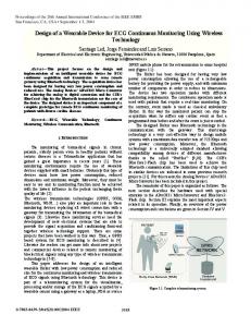
Fig. 7. Example of one channel of generated nerve activity consisting of 50 APs with random velocities between 10–50 m/s (a data block of 1200 samples was used here). Data are repeated continuously. Smooth data block transition is ensured (see at time 6 ms) by “wrapping around” of APs.
Fig. 6. Simplified flow diagram of the main program loops beginning with startup.
The flow of the main program loops for UM and AM is shown in Fig. 6. Care is taken in the program design to provide immediate response to user input. Still, since data for all eight channels must be prepared by the single controller, real-time data processing during emulation is not feasible. Instead, a data table is prepared in memory in response to user input which is then played back, ensuring a constant output rate of just above 5 s/sample. Fixed-point representation using 6-bit fractional and 10-bit integer parts is employed throughout the synthesis routine to maximize processing speed. Although samples are generated at 5 s intervals, the time step for internal calculation is reduced to 1.25 s to allow even smaller phase differences to be resolved. The TMAP template values (spaced at 5 s intervals) are interpolated when required using a linear function. Preparing 896 data points per channel for eight channels, superposing three AP velocity groups and storing the result to internal flash memory completes within about 2.5 seconds. Although this is a suitably fast response for the CAP scenario, generating the more than 50 APs needed for natural traffic would cause an inconvenient delay. Therefore, for these scenarios, data tables are prepared and downloaded to the AM offline. The TMAP template function is used and random values for relative delays and velocities are assigned to the individual APs. Using local memory to hold data tables results in a limited playback time . This is unproblematic in the CAP scenario as, for example, even a slow AP propagating at 10 m/s has travelled a distance of 4.48 cm within the 4.48 ms corresponding to 896 samples, sufficient for most practical cuff lengths. After this time, given by (4), has decayed to zero. In the natural traffic scenarios which yield permanent activity the data are continuously repeated. At the current output rate is restricted to about 6 ms. To avoid discontinuities between the cycles the data is wrapped around, i.e., each individual AP that leaves the time window “to the right” reenters “from the left”. In this way, the generated data can be looped without introducing artifacts
Fig. 8. Photograph of the prototype emulator on a printed circuit board mounted inside a polystyrene enclosure. Eight data channels (electrode output leads) are available.
as shown by the sample data in Fig. 7. To let even the slowest AP traverse the length of the cuff within the time span covered by the data table the minimum velocity that can be emulated in this scenario is given by (5) Currently, each AP is generated once per data block. This results in identical firing rates for all velocities (which is suitable for our application where we try to find characteristic spectra for the activity in a velocity band given a uniform activity distribution). Variable firing rates could be implemented by placing multiple copies of the AP at different time positions within the data block. III. MEASURED RESULTS A. Bench Test A photo of the prototype PCB inside a polystyrene enclosure is shown in Fig. 8. The board is powered by a 5 V battery supply. The ground reference voltage in Fig. 4 is assigned a separate routing network on the PCB but eventually connects to the
942
IEEE TRANSACTIONS ON NEURAL SYSTEMS AND REHABILITATION ENGINEERING, VOL. 22, NO. 5, SEPTEMBER 2014
Fig. 9. Measured monopolar waveforms for three travelling CAPs stimulated . AP velocities can be distinguished as marked by the lines interconat necting the AP peaks.
battery voltage . The test amplifiers require a 9 V dual test power supply which can be disconnected when the devices are not in use. The use of batteries results in a stand-alone solution not requiring additional wiring or connection to a computer. The pickup of interference or ground coupling is thus kept to a minimum. The system consumes 120 mW (excluding the test amplifiers) and the material costs for the assembly are approximately 40 USD. For the following bench tests the emulator was programmed with the following cuff parameters: 15 mm cuff length, 1.5 mm electrode pitch, first electrode located at 1.5 mm from the proximal end of the cuff and 2.5 mm distance between proximal cuff edge and stimulation point on the nerve. In a first measurement the system was set to produce artificially stimulated CAPs. The DAC outputs were observed before the resistive divider, at test points in Fig. 4, using a digital storage oscilloscope (TDS5104, Tektronix). The measured monopolar waveforms of all eight channels are reproduced in Fig. 9. Three AP groups with different velocities can be distinguished in this recording. Starting at the same time after stimulation (the negative edge of the stimulation pulse was used to trigger the oscilloscope) the APs spread out with time. The most distant channel is labeled CH8. The fastest AP yields the highest amplitude as expected from (3). The three user selected velocities (10, 20 and 90 m/s in this measurement) are verified by determining the time delay between the AP peaks between channels as marked out in Fig. 9. Further measurements were obtained for the natural nerve traffic scenarios. The oscilloscope data for channels 2–4 at the high-velocity range is shown in Fig. 10 (equivalent results were obtained for the other channels but are not shown here for clarity). An example of the principle waveform observed in the low-velocity regime on channel 1 is shown in Fig. 7. As application example, the velocity spectra were evaluated for both the low-range and high-range traffic. This was accomplished in MATLAB (The MathWorks, USA) by forming tripole signals from the monopolar measurements, delaying the data channels, summing the delayed waveforms and plotting the signal power at the relevant frequency as described in detail in [12]. The values thus obtained are used as a simple metric for
Fig. 10. DAC output voltages measured for three channels in the natural traffic mode and high-velocity APs between 50–100 m/s.
Fig. 11. Velocity plot of the recorded activity when the emulated range was 10–50 m/s and 50–100 m/s, respectively.
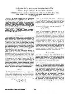
the activity at the chosen velocity and are plotted in the velocity spectrogram in Fig. 11. Despite the simplicity of the algorithm the different concentration of signal power can be identified for the two velocity ranges, exemplifying the potential of the emulator for evaluating VSR processing front ends. Eventually, the attenuation network was tested. Overlapping APs of similar velocity were generated using the CAP scenario. The test amplifiers contained on the PCB were connected to the electrode output nodes and in Fig. 4. The amplifier gain of 61 dB compensates for the attenuation of the resistive divider network, so that the amplified output signal can be compared directly to the DAC output signal at nodes and , respectively. The oscilloscope waveforms are shown in Fig. 12, confirming the correct electrode output signals. A certain level of interference is visible on the amplified signals. This is due to the fast switching digital lines connecting the AM to the DACs which couple transients into the output lines after the attenuation stage. This can be improved by rerouting the DAC tracks in a future redesign of the system. For the intended application setup this interference is not problematic as it consists of a large common-mode portion which cancels when dipole (differential) signals are formed. Furthermore, the interfering signal is concentrated at very high frequencies above 100 kHz.
RIEGER et al.: DEVICE FOR EMULATING CUFF RECORDINGS OF ACTION POTENTIALS PROPAGATING
Fig. 12. Comparison of the voltages generated by the DAC and the attenuated electrode output signal observed through test amplifiers with 61 dB gain and 100 kHz bandwidth.
943
Fig. 13. Activation of fast fibers in vitro by low stimulation intensity with rem/s. Each tripole channel curve (solid line) is an ensemble of sulting 60 repeated measurements. Recorded emulator output for this scenario is shown for comparison (dashed line). Channel offsets are introduced offline for clarity.
TABLE II SUMMARY OF EMULATOR SPECIFICATIONS
A summary of the emulator specifications is given in Table II. B. Comparison with In Vitro Results A cuff electrode based on polyimide thin film technology [28] was employed for obtaining measured results in an in vitro setup using frog nerves. The self-spiralling cuff is 40 mm long, the electrode pitch is 3.5 mm, and the first electrode is located 2.5 mm from the cuff edge. The emulator was reprogrammed using these parameters to yield comparable results. The 80–90 mm long sections of sciatic nerves were explanted from decapitated Xenopus Laevis frogs and immersed in amphibian Ringer’s solution [29] at room temperature (approximately 22 C). In total, four sciatic nerves of three frogs were used to conduct all measurements. We previously described these experiments in [18]. For each measurement, 60 repetitive stimuli were applied, the resulting monopolar CAPs were recorded with a bandwidth of 3.3 kHz. Six tripole signals were subsequently calculated offline using the first (proximal) eight signal channels. In a first experiment, CAPs with predominantly high velocity were elicited by setting the stimulation pulse amplitude to just above the stimulation threshold of the nerve. The recording of the subsequent 60 measurements is shown in Fig. 13. The observed CAP amplitude is around 50 V , the velocity about 41 m/s. Also shown in Fig. 13 are the measured results obtained from the emulator for comparison. Visual inspection shows that the emulator response matches the data from the frog nerve experiment well. Specifically, the onset of the AP as determined by the most negative AP deflection lies within the envelope obtained by plotting the 60 in vitro measurements. This also applies to the AP peak-to-peak amplitude, except for the outermost
Fig. 14. Activation of slow fibers in vitro by high stimulation intensity and m/s. Each tripole channel curve blocking of fast fibers, resulting in (solid line) is an ensemble of 60 repeated measurements. Recorded emulator output for this scenario is shown for comparison (dashed line). Channel offsets are introduced offline for clarity.
channels 1, 5 and 6, where the amplitudes differ by a maximum of 17%. In a second experiment only slow fibers are activated, which requires the use of an additional blocking cuff and a blocking generator. The stimulation intensity was first set to a supramaximal level, ensuring the electrical activation of as many fibers inside the peripheral nerve as possible. Then, the blocking generator was switched on, generating a high-frequency current pattern which blocked the activity of the large (fast) fibers [30], [31]. The resulting recordings are shown in Fig. 14. Travelling CAPs are visible with a velocity of 20 m/s and approximately 35 V amplitude. Comparison with the emulated signals shows that also for this setup the emulator provides a response which is consistent with the experimental recordings. Finally, the blocking cuff is deactivated, and the entire fiber population is excited using a large stimulus amplitude (2.2 mA with 200 s pulsewidth). The CAP signal amplitude is measured as about 100 V . From the recording it is estimated that the three dominant AP velocities are 12, 31, and 41 m/s, respectively. The emulator is set up to generate three superimposed APs with these velocities and a distance between stimulation site and cuff edge of 11 mm. The in vitro recordings and the measured emulator response are both shown in Fig. 15. The emulator matches the in vitro response well especially at the higher
944
IEEE TRANSACTIONS ON NEURAL SYSTEMS AND REHABILITATION ENGINEERING, VOL. 22, NO. 5, SEPTEMBER 2014
Fig. 15. Activation of complete fiber population in vitro by high stimulation intensity. Each tripole channel curve (solid lines) is an ensemble of 60 repeated measurements. Recorded emulator output is shown with dashed lines for three , 31, 41 m/s. Channel offsets are introduced offline for clarity. APs with
velocities. The 12 m/s AP in emulation is visible as a clear propagating spike, whereas the in vitro signal is less defined. This is explained by activation of additional fiber populations in vitro, resulting in a more widely spread range of velocities, and further by a spreading of the physical activation area due to using a very high stimulation current. IV. DISCUSSION AND CONCLUSION The design and implementation of a prototype axon emulator system is presented which provides a realistic interface in terms of its load resistance and the spatial dynamics of the AP propagation. It is intended for the evaluation of novel systems for the recording and processing of nerve signals, e.g. VSR, where very detailed modeling of nerve physiology or electrode properties is not required. The emulator does not facilitate the design and evaluation of the front-end properties of nerve and cuff in the first place. For novel interface configurations real nerve data are still needed to adapt the analytical nerve model. Once the model is adjusted, characterization and tuning of the recording system can be carried out using the emulator. Additional effects, e.g., subthreshold response of an axon and AP amplitude dependence on temperature, are currently not included so that the approach is most suitable when well-defined and reproducible results are required. Principally, temperature dependence can be emulated by varying parameter in (2) with temperature. The emulated waveforms are synthesized from a TMAP template as an approximation of a typical membrane voltage. Employing this simple approximation enables near real-time pattern generation. The template-based approach further allows the emulator to be reconfigured easily and produce waveforms of the desired properties. Waveform synthesis is based on a simplified model of nerve and cuff. It is expected that this model can be applied with modifications to other configurations as well, i.e., contact matrix, FINE and LIFE. For the extraneural interfaces, the AP amplitudes in (2) can be scaled by appropriate factors to represent fascicle selectivity. However, larger emulation error is anticipated for the LIFE design due to its axonal position sensitivity but also due to a varying quality in electrical insulation of the recording area provided by the epineurium, affecting the assumption of linear potential gradients made in deriving the model (4).
Compared to simple electromechanical emulators [31] this emulator provides a considerably more convenient electrical interface with advanced functionality and multiple channels. Compared with PC-based signal generation and use of highspeed arbitrary function generators this emulator: 1) is more cost efficient; 2) provides a truly portable solution; 3) offers an interface yielding microvolt level output signals; 4) enables short wire connections and battery operation which both minimize interference coupling. Predefined scenarios are user selectable and provide convenient device operation during experimentation. Measured results from a prototype emulator confirm its operation and a comparison with in vitro recordings validates the results. The presented example for VSR further shows that for this application the emulator yields results useful for testing setups working in the velocity spectrum domain. Once the properties of the electrode-nerve front end have been established and can be approximated by the emulation model (as for the cuff with ring electrodes presented here), it is expected that the emulator helps reduce the number of initial inconclusive animal experiments and further reduces the cost, effort and time required for testing new circuits and methods for nerve signal recording by moving the need for a physical in vivo/in vitro preparation and electrode fabrication to the final stages of system implementation. REFERENCES [1] G. A. M. Kurstjens, “Nerve conduction velocity selective recording using a multi-contact cuff electrode—A case study of in vitro vagus nerve preparation,” in Proc. 15th IEEE Nordic-Baltic Conf. Biomedical Engineering Medical Physics, 2011, pp. 261–263. [2] D. Loi, C. Carboni, G. Angius, G. N. Angotzi, M. Barbaro, L. Raffo, S. Raspopovic, and X. Navarro, “Peripheral neural activity recording and stimulation system,” IEEE Trans. Biomed. Circ., vol. 5, no. 4, pp. 368–379, Aug. 2011. [3] C. C. K. Lin, M. S. Ju, and H. S. Cheng, “Model-based ankle joint angle tracing by cuff electrode recordings of peroneal and tibial nerves,” Med. Biol. Eng. Comput., vol. 45, no. 4, pp. 375–385, Apr. 2007. [4] J. Taylor and R. Rieger, “A low noise front-end for multiplexed ENG recording using CMOS technology,” Analog Integr. Circ. S., vol. 68, no. 2, pp. 163–174, Aug. 2011. [5] K. Yoshida, G. A. M. Kurstjens, and K. Hennings, “Experimental validation of the nerve conduction velocity selective recording technique using a multi-contact cuff electrode,” Med. Eng. Phys., vol. 31, no. 10, pp. 1261–1270, Dec. 2009. [6] K. Yoshida, D. Farina, M. Akay, and W. Jensen, “Multichannel intraneural and intramuscular techniques for multiunit recording and use in active prostheses,” Proc. IEEE, vol. 98, no. 3, pp. 432–449, Mar. 2010. [7] N. Donaldson, R. Rieger, M. Schuettler, and J. Taylor, “Noise and selectivity of velocity-selective multi-electrode nerve cuffs,” Med. Biol. Eng. Comput., vol. 46, no. 10, pp. 1005–1018, Oct. 2008. [8] J. J. Struijk, M. Thomsen, J. O. Larsen, and T. Sinkjaer, “Cuff electrodes for long-term recording of natural sensory information,” IEEE Eng. Med. Biol., vol. 18, no. 3, pp. 91–98, May–Jun. 1999. [9] X. Navarro, T. B. Krueger, N. Lago, S. Micera, T. Stieglitz, and P. Dario, “A critical review of interfaces with the peripheral nervous systemfor the control of neuroprostheses and hybrid bionic systems,” J. Periph. Nerv. Syst., vol. 10, pp. 229–258, 2005. [10] J. Zariffa, M. K. Nagai, Z. J. Daskalakis, and M. R. Popovic, “Influence of the number and location of recording contacts on the selectivity of a nerve cuff electrode,” IEEE Trans. Neur. Syst. Rehab. Eng., vol. 17, no. 5, pp. 420–427, 2009. [11] K. Yoshida and R. B. Stein, “Characterization of signals and noise rejection with bipolar longitudinal intrafascicular electrodes,” IEEE Trans. Biomed. Eng., vol. 46, no. 2, pp. 226–234, 1999. [12] J. Taylor, N. Donaldson, and J. Winter, “Multiple-electrode nerve cuffs for low-velocity and velocity-selective neural recording,” Med. Biol. Eng. Comput., vol. 42, no. 5, pp. 634–643, Sep. 2004.
RIEGER et al.: DEVICE FOR EMULATING CUFF RECORDINGS OF ACTION POTENTIALS PROPAGATING
[13] J. J. Struijk, “On the spectrum of nerve cuff electrode recordings,” in Proc. 19th Ann. Int. Conf. EMBS, 1997, vol. 5, pp. 2006–2007. [14] E. Stålberg and L. Karlsson, “The motor nerve simulator,” J. Clin. Neurophysiol., vol. 112, no. 11, pp. 2118–2132, Nov. 2001. [15] J. J. Struijk, “The extracellular potential of a myelinated nerve fiber in an unbounded medium and in nerve cuff models,” Biophys. J., vol. 72, no. 6, pp. 2457–2469, Jun. 1997. [16] R. Rieger, M. Schuettler, D. Pal, C. Clarke, P. Langlois, J. Taylor, and N. Donaldson, “Very low-noise ENG amplifier system using CMOS technology,” IEEE T. Neur. Sys. Reh., vol. 14, no. 4, pp. 427–437, Dec. 2006. [17] M. Sahin and D. M. Durand, “Improved nerve cuff electrode recordings with subthreshold anodic currents,” IEEE Trans. Biomed. Eng., vol. 45, no. 8, pp. 1044–1050, Aug. 1998. [18] M. Schuettler, N. Donaldson, V. Seetohul, and J. Taylor, “Fibre-selective recording from the peripheral nerves of frogs using a multi-electrode cuff,” J. Neur. Eng., vol. 10, 2013, online. [19] R. Rieger and J. Y. Chen, “An axon emulator for evaluation of nerve recording systems,” in Proc ISCAS 2012, May 2012, pp. 1528–1531. [20] Microchip Technology Inc., PIC18F2420/2520/4420/4520 Data Sheet: 28/40/44-Pin Enhanced Flash Microcontrollers with 10-Bit A/D and nanoWatt Technology datasheet DS39631E, 2008. [21] Analog Devices Inc., 3 V/5 V, Rail-to-Rail Quad, 8-Bit DAC AD7304/ AD7305 datasheet rev. C, 2004. [22] J. Clark and R. Plonsey, “The extracellular potential field of the single active nerve fiber in a volume conductor,” Biophys. J., vol. 8, no. 7, pp. 842–864, Jul. 1968. [23] M. S. Lewicki, “A review of methods for spike sorting: The detection and classification of neural action potentials,” Netw.: Comput. Neural Syst., vol. 9, pp. R53–R78, 1998. [24] S. Micera, L. Citi, J. Rigosa, J. Carpaneto, S. Raspopovic, G. Di Pino, L. Rossini, K. Yoshida, L. Denaro, P. Dario, and P. M. Rossini, “Decoding information from neural signals recorded using intraneural electrodes: Toward the development of a neurocontrolled hand prosthesis,” Proc. IEEE, vol. 98, no. 3, pp. 407–417, Mar. 2010. [25] W. Rall, “Distinguishing theoretical synaptic potentials computed for different soma-dendritic distributions of synaptic input,” J. Neurophysiol., vol. 30, no. 5, pp. 1138–1168, Sep. 1967. [26] B. Frankenhaeuser and A. F. Huxlej, “The action potential in the myelinated nerve fibre of xenopus laevis as computed on the basis of voltage clamp data,” J. Physiol., vol. 171, no. 2, pp. 302–315, Jun. 1964. [27] N. T. Camevale and M. L. Hines [Online]. Available: http://www. neuron.yale.edu/neuron/, 2013 [28] T. Stieglitz, H. Beutel, M. Schuettler, and J.-U. Meyer, “Micromachined polyimide-based devices for flexible neural interfaces,” Biomed. Microdevices, vol. 2, no. 4, pp. 283–294, Dec. 2000. [29] A. Flores, M. Leon-Olea, R. Vage, and V. Soto, “Histochemistry and role of nitric oxide synthase in the amphibian (Ambystoma tigrinum) inner ear,” Neurosci. Lett., vol. 205, no. 2, pp. 131–134, Feb. 1996. [30] K. L. Kilgore and N. Bhadra, “Nerve conduction block utilising highfrequency alternating current,” Med. Biol. Eng. Comput., vol. 42, no. 3, pp. 394–406, May 2004. [31] R. P. Williamson and B. J. Andrews, “Localized electrical nerve blocking,” IEEE Trans. Biomed. Eng., vol. 52, no. 3, pp. 362–370, Mar. 2005.
945
[32] L. N. S. Andreasen, J. J. Struijk, and M. Haugland, “An artificial nerve fiber for evaluation of nerve cuff electrodes,” in Proc. 19th IEEE EMBC Annu. Int. Conf., 1997, pp. 1997–1999. Robert Rieger (S’01–M’04–SM’08) received the B.Eng. degree from the University of Kent, Canterbury, U.K., in 2000, and the Ph.D. degree in electrical and electronics engineering from University College London (UCL), London, U.K., in 2004. From 2004 to 2005, he was a Design Engineer with austriamicrosystems AG (AMS), Rapperswil, Switzerland. He joined the Electrical Engineering Department, National Sun Yat-Sen University, Kaohsiung, Taiwan, in 2006, where he is now a Professor and heads the Bionics Integrated Systems Laboratory. His research interests are in the area of low-power electronics for biomedical application and bio-chip design. Dr. Rieger is a member of VDE. He is also member of the IEEE Technical Committees on BioCAS, VLSI Systems and Applications (VTA), CAS Education and Outreach and an Associate Editor for IEEE TRANSACTIONS ON BIOMEDICAL CIRCUITS AND SYSTEMS.
Martin Schuettler (M’99) studied electrical engineering at the Technical University of Braunschweig, Germany, and received the Ph.D. degree in peripheral nerve stimulation electrodes from Saarland University, Germany, in 2002. From 2003 to 2005, he was with the Implanted Devices Group, University College London, U.K., as a Postdoctoral Fellow, working on strategies of selective peripheral nerve recordings. He had several extended visits to the Australian Visual Prostheses Group. Since 2005, he has been Group Leader at the Laboratory for Biomedical Microtechnology, University of Freiburg, Germany. In 2010, he cofounded CorTec, a company developing and commercializing human implantable brain–machine interfaces, of which he holds the position of CTO. He is Principle Investigator of the Freiburg Brain-Machine Interface Initiative and has published more than 150 peer-reviewed papers, abstracts and book chapters.
Sheng-Chih Chuang was born in Pingtung, Taiwan, in 1988. He joined the Bionics Integrated Systems Laboratory, National Sun Yat-Sen University, in 2012 where he is currently working toward the M.S. degree in electrical engineering. His main research focus is on the implementation of a mixed-signal integrated velocity-selective nerve signal processor in CMOS technology.