section 4. In section 5 we consider the probability of collision between multiple objects. II. PROBLEM STATEMENT. A. Vehicle and obstacle models. The vehicle ...
A Fast Monte Carlo Algorithm for Collision Probability Estimation Alain Lambert IEF, UMR CNRS 8622 Université Paris Sud-XI Bat. 220, Centre d’Orsay 91405 Orsay cedex - France Abstract—In order to navigate safely, it is important to detect and to react to a potentially dangerous situation. Such a situation can be underlined by a judicious use of the locations and the uncertainties of both the navigating vehicle and the obstacles. We propose to build an estimation of the collision probability from the environment perception with its probabilistic modeling. The probability of collision is computed from a sum of integral of a product of Gaussians. The integrals takes into account the uncertain configurations and the volume of both the vehicle and the obstacles.
I. I NTRODUCTION The anticipation of collision is necessary for a safe navigation. The prediction of collisions could be used for obstacle avoidance, speed monitoring or path planning. Such a prediction has been computed in various way during the last years. [1] defines a security area modeled by a circle (centered on the robot position) whose radius is proportional to the speed. A collision judgment is based on an intersecting test between this circle and high-confidence position error ellipses. Controlling the speed and steering of the mobile robot along a preplanned path is done by using the collision judgment. [2] uses an interaction component (deformable virtual zone) of the robot with the environment which leads to avoidance-oriented control laws. Furthermore an emergency area around the robot causes an emergency stop if it is broken by an obstacle. [3] performs an on line speed monitoring by computing a time to collision. The farthest is the collision and the highest is the speed. In order to detect a collision, the authors grow a mobile robot with its uncertainty ellipse and they do a collision test between the resulting shape and the obstacles. The process is repeated all along the path so as to compute a time to collision. [4] computes a distance to undecided regions (unknown region) or to nearby obstacles. Next they use this distance information to compute a speed. We think that only using a measured distance to collision [4][5] is not sufficient as the real distance could be quite different and lead to unexpected collision. Using a security area [1][2] around the vehicle is a good idea only if this security area represents the uncertainty on the vehicle location. Nevertheless such an area (an ellipse [3]) is a discrete and binary representation of a continuous probability of presence. Most authors uses an ellipse which represents the probability of presence of the vehicle at 90%. It is a shame to define a threshold and to loose information for higher level algorithms.
Dominique Gruyer, Guillaume Saint Pierre LIVIC INRETS/LCPC Bat 824, 14 route de la minière 78000 Versailles Satory - France That’s why in this paper we propose to use the entire available information (the pdf of the vehicle and the obstacles) for defining a probability of collision. Such an approach have been followed in [6] for a punctual robot and a geometrical obstacle without considering the uncertainty in orientation. We are going to overcome those restrictions (punctual and no uncertainty in orientation) in order to compute a realistic collision probability for real world application. To the best of our knowledge, it is the first time that the 3D uncertainty and the volume of the objects are used when calculating the probability of collision. In the next section we introduce the necessary models. In section 3 we propose an analytical formula for computing the probability of collision between two configurations. We have no analytical solution when considering objects instead of configurations. That is why we propose an algorithm in section 4. In section 5 we consider the probability of collision between multiple objects. II. P ROBLEM STATEMENT A. Vehicle and obstacle models The vehicle configuration is denoted xv = (xv , yv , θv )T where (xv , yv ) are the coordinates of a characteristic point which is located midway between the two rear wheels of our vehicle and θv is its orientation. All variables are defined with respect to the global frame. The obstacles configuration is denoted xo = (xo , yo , θo )T . Both vehicle and obstacles are represented as polygonal lines in a 2D world map and their surfaces are denoted Vv and Vo . The geometric center of Vo is xo . B. Uncertainty modeling The pdf (probability density function) of a configuration x having a C covariance matrix and an x ˆ mean is : p(x) = √
2π
1 �n √
e− 2 ((x−ˆx) 1
det Σ
T
Σ−1 (x−ˆ x))
(1)
where n is the x dimension. We consider that x dimension is 3 for the sake of simplicity : x = (x, y, θ)T (nevertheless the x dimension can be higher). p(x) = √
2π
1 �3 √
e− 2 ((x−ˆx) 1
det Σ
T
Σ−1 (x−ˆ x))
(2)
where Σ is a 3x3 covariance matrix : σx2 ρxy σx σy ρxθ σx σθ σy2 ρyθ σy σθ Σ = ρxy σx σy ρxθ σx σθ ρyθ σy σθ σθ2
(3)
Such a matrix could be the result of a filter process like the Extend Kalman Filter or could be directly defined by: � � b) (x − x b)T Σ = E (x − x (4) The pdf of a v vehicle and an o obstacle are denoted pv and po with their associated Σv and Σo matrices. Finally, v and o are defined by : v = (xv , Σv, Vv ) and o = (xo , Σo, Vo ) III. P ROBABILITY OF COLLISION BETWEEN 2 UNCERTAIN CONFIGURATIONS
The probability of collision between a v and an o uncertain configurations (assuming that Vv = Vo = ∅) is defined by : ZZZ pcoll (v, o) = pv (x, y, θ) � po (x, y, θ).dxdydθ
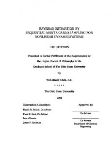
Figure 1. pdf of the collision between an obstacle and a vehicle moving in straight line
R2 ×[0,2π[
(5) The integral 5 can be analytically computed. Details of the calculations in the multivariate case can be found in appendix A. Let’s assume that pv (x, y, θ) is the density of a Nd (b xv , Σv ) distribution, and po (x, y, θ) the density of a Nd (b xo , Σo ) . Let bv ) + bv )0 Σ−1 us denote x = (x, y, θ), A = (x − x v (x − x 0 −1 bo ) and B = [x − m]0 Σ−1 [x − m] bo ) Σo (x − x (x − x with: bv + Σ−1 bo m = Σ−1 Σ−1 v x o x −1 Σ−1 = Σ−1 v + Σo
�
�
(6) (7)
We have �p � det (Σ) exp − 12 (A − B) p p pcoll (v, o) = det (Σv ) det (Σv )
IV. P ROBABILITY OF COLLISION BETWEEN 2 OBJECTS WITH G AUSSIAN UNCERTAINTIES (8)
with A−B=
b0v Σ−1 bv + x b0o Σ−1 bo x v x o x �0 −1 −1 bv + Σo x bo Σ−1 − Σv x
bv + Σ−1 bo Σ−1 v x o x
vehicle (0.13). Consequently the pdf of the collision has been multiplied by 100 on figure 1 for a better visualization. The probability of collision computed using equation (8) is equal to 0.007. It allows us to conclude that the situation is safe which is unrealistic considering the real situation with the volume of the cars. We should have thought about taking into account the volumes as they are big regarding the distance between the vehicles. We have not investigate the interest of equation (8) when the volume are not null because the following approach (see the next section) provide good enough results both in term of computing time and precision.
� (9)
Equation (8) has been used to compute the probability of collision of figure 1. During this experiment corresponding to a real outdoor situation, a car (so called “the vehicle”, right part of the figure) was running on its way whereas there was another static car (so called “the obstacle”) on the other way (left part of the figure). The vehicle was moving from the bottom to the top of the figure in straight line using only its proprioceptive sensors. The pdf of the vehicle is shown at 6 different time instants (every 4 meters). The pdf of the collision has been computed at each of those time instants but only 2 pdf are noticeable. The maximum height of the biggest pdf of the collision is tiny (0.00205) compared to the corresponding pdf of both the obstacle (0.16) and the
A. Analytical description of the problem The probability of collision between a v and an o polygonal objects is the probability that v and o share a same part of the space. Consequently, given a v configuration (with a pv associated probability and a Vv volume) and an o configuration (with a po associated probability and a Vo volume) the probability of collision is given by: R pcoll (v, o) = D pv (xv , yv , θv )� (10) po (xo , yo , θo )dxv dyv dθv dxo dyo dθo with D = { (xv , yv , xo , yo ) ∈ R4 , (θv , θo ) ∈ [0, 2π[ 2 \ Vv (xv , yv , θv ) ∩ Vo (xo , yo , θo ) 6= ∅}
(11)
If v and o are punctual objects then equation 10 turn to equation 5. If v and/or o have an infinite volume then v and o always collide and equation 10 equals one.
Algorithm 1 Probability of collision between v and o 1: function S LOW P ROBABILITYO F C OLLISION (v, o) 2: pcoll (v, o) ← 0 3: for i ←1 to N do 4: xv ← randc(b x v , Σv ) 5: for j ←1 to N do 6: xo ← randc(b x o , Σo ) 7: if Vv (xv ) ∩ Vo (xo ) 6= ∅ then 8: pcoll (v, o) ← pcoll (v, o) + 1 9: end if 10: end for 11: end for 12: pcoll (v, o) ← pcollN(v,o) 2 13: return(pcoll (v, o)) 14: end function
the product of two functions f and h by : Z m 1 X f (y)h(y)dy = h(yj ) m j=1
Inside this Monte Carlo approximation, (y1 , ..., ym ) are samples generated by following the pdf f (y). Thanks to Eq. (14) we can rewrite the right part of Eq. (12) as: Z 2π Z +∞ Z +∞ po (xo , yo , θo ).Υ.dxo dyo dθo 0
B. Monte Carlo solution As we have no analytical solution to equation 10, we propose to use a MC (Monte Carlo) method. Firstly, we need to rewrite Eq. (10) as : 2π
+∞
Z
−∞ +∞
Z
Z
+∞
pcoll (v, o) =
[pv (xv , yv , θv ). 0
Z
2π Z
−∞ +∞
po (xo , yo , θo ). 0
−∞
−∞
Υ.dxo dyo dθo ].dxv dyv dθv
−∞ m
−∞
1 X = Υ(V(xv , yv , θv ), V(xoj , yoj , θoj )) m j=1
Algorithm 2 Faster computing of the probability of collision between v and o 1: function FAST P ROBABILITYO F C OLLISION (v, o) 2: pcoll (v, o) ← 0 3: for j ←1 to N do 4: xv ← randc(b x v , Σv ) 5: xo ← randc(b xo , Σo ) 6: if Vv (xv ) ∩ Vo (xo ) 6= ∅ then 7: pcoll (v, o) ← pcoll (v, o) + 1 8: end if 9: end for 10: pcoll (v, o) ← pcollN(v,o) 11: return(pcoll (v, o)) 12: end function
Z
(14)
(12)
Where Υ = Υ(Vv (xv , yv , θv ), Vo (xo , yo , θo )) is a collision test between the volume Vv of the vehicle and the volume Vo of the obstacle:
(15)
and using Eq. (14) and (15) allows us to rewrite Eq. (12) as: Pm Pm � j=1 pcoll (v, o) = i=1 Υ V(xvi , yvi , θvi ), V(xoj , yoj , θoj ) m m (16) Which can be rewritten as: m � 1 X Υ V(xvi , yvi , θvi ), V(xoj , yoj , θoj ) pcoll (v, o) = 2 m i,j=1 (17) Where ((xv1 , yv1 , θv1 ), ..., (xvm , yvm , θvm )) and ((xo1 , yo1 , θo1 ), ..., (xom , yom , θom )) are samples generated by following the pdf pv (xv , yv , θv ) and po (xo , yo , θo ). Drawing of samples is done as explained in appendix B. We assume that such a drawing is done by a randc() function. Algorithm 1 is the implementation of equation 17. The complexity of this algorithm is 0(N 2 ) where N = m is a number that determine the accuracy of the integral computation. Unfortunately we need a value of N of the order of 104 to obtain “good results” (see figures 2, 3, 4 and section IV-C). Consequently we propose to rewrite Eq. (17) as : m
1 X Υ (V(xvi , yvi , θvi ), V(xoi , yoi , θoi )) m i=1 (18) The sum of sum has been replaced by a single sum and the samples are now drawn simultaneously (in Eq. (17) we drawn m samples of o for 1 sample of v). The equation (18) leads to algorithm 2 with a linear complexity in O(N ) which is much more better than algorithm 1. Unfortunately we need an higher number for N (in algorithm 2 comparatively to algorithm 1) in order to achieve a good accuracy. Nevertheless we are going to see in the next section that the N value needed in algorithm 2 is very inferior to N 2 value needed in algorithm 1. pcoll (v, o) =
C. Experimental results Υ(Vv (xv , yv , θv ), Vo (xo , yo , θo )) = � 1 if Vv (xv , yv , θv ) ∩ Vo (xo , yo , θo ) 6= ∅ 0 if Vv (xv , yv , θv ) ∩ Vo (xo , yo , θo ) = ∅ (13) Secondly we know that we can approximate the integral of
Results provided by algorithms 1 and 2 have been compared on figures 2, 3 and 4. The two algorithms have approximated 3 different values of the probability of collision : an high (figure 2), an medium (figure3) and a low value (figure4). For each value the algorithms have been ran 10 times (although one run is sufficient to obtain an estimate of the
1
1
0.14 FastProbabilityOfCollision Algorithm Exact probability of collision
0.95
0.9
0.9
0.85
0.8
0.75
0.8
0.75
0.7
0.65
0.65
0.6
0
1000
2000
3000
4000 5000 6000 Number of samples
7000
8000
9000
10000
1000
2000
3000
4000 5000 6000 Number of samples
8000
9000
0.5
0.4
0.3
0.3
0.2
0.1
0.1
4000 5000 6000 Number of samples
7000
8000
9000
10000
(a) "Slow Probability Of Collision" algorithm Figure 3.
1000
2000
3000
4000 5000 6000 Number of samples
7000
8000
9000
10000
0
SlowProbabilityOfCollision Algorithm FastProbabilityOfCollision Algorithm 0.3
0.4
0.2
3000
0
0.35
Root mean square error of the probability of collision
0.5 Probability of collision
0.6
2000
0.04
(c) Comparison of errors between both algorithms
FastProbabilityOfCollision Algorithm Exact probability of collision
0.6
1000
0.06
0
10000
0.7
0
0.08
Comparison between the Slow and Fast algorithms for a high probability of collision
SlowProbabilityOfCollision Algorithm Exact probability of collision
Probability of collision
7000
(b) "Fast Probability Of Collision" algorithm
0.7
0
0.1
0.02
0
(a) "Slow Probability Of Collision" algorithm Figure 2.
0.12
0.85
0.7
SlowProbabilityOfCollision Algorithm FastProbabilityOfCollision Algorithm
Root mean square error of the probability of collision
0.95
Probability of collision
Probability of collision
SlowProbabilityOfCollision Algorithm Exact probability of collision
0.25
0.2
0.15
0.1
0.05
0
1000
2000
3000
4000 5000 6000 Number of samples
7000
8000
9000
10000
(b) "Fast Probability Of Collision" algorithm
0
0
1000
2000
3000
4000 5000 6000 Number of samples
7000
8000
9000
10000
(c) Comparison of errors between both algorithms
Comparison between the Slow and Fast algorithms for a medium probability of collision
probability) with until 104 samples for each run (N = 100 in algorithm 1 and N = 104 in algorithm 2). Consequently subfigures .a and .b have 10 curves (plus the line of the exact value) and we can analyze various results of the algorithms on three typical situations. For each figure the “exact probability” is the mean between the two algorithms after 106 samples. On each figure the slow algorithm defines a large corridor around the exact value whereas the fast algorithm defines a thinner corridor. It shows the property of the fast algorithm to define ( in a lower time) better and more regular results than the slow algorithm. It is underlined on figures 2.c, 3.c and 4.c where the root mean square error (RMSE) is computed for both algorithms. RMSE is always lower (2 to 10 times after more than 500 samples) for the fast algorithm than for the slow algorithm on each of our attempts. For high and medium probability of collision, the accuracy (maximum error) after 1000 samples is about 0.15 for the slow algorithm whereas it is less than 0.05 for the fast algorithm. Considering the low (0.011) probability of collision (figure 4), the accuracy is 0.03 for the slow algorithm and 0.005 for the fast algorithm. Both algorithms compute the probability of collision with 104 samples (one run) in about 0.01 second on a Pentium IV processor (2 Ghz). Consequently, the fast algorithm outperforms the slow algorithm considering both computing time and precision.
Approximating the probability of collision takes 1 millisecond if we consider that only 103 samples are necessary (for algorithm 2). Consequently such an algorithm can be embedded on a vehicle and deals with multiple obstacles as described in the next section. V. P ROBABILITY OF COLLISION BETWEEN AN OBJECT AND OTHER OBJECTS WITH G AUSSIAN UNCERTAINTIES A. Analytical description of the problem The probability that v collides with at least one obstacle can be calculated through the probability that v do not collides with any obstacles : pcoll (v, o1 ...on ) = 1 − pcoll (v, o1 ) · . . . · pcoll (v, on )
(19)
The probability that v do not collide with oi obstacle is Z 2π Z +∞ Z +∞ pcoll (v, oi ) = [pv (xv , yv , θv ). 0 −∞ −∞ Z 2π Z +∞ Z +∞ poi (xoi , yoi , θoi ). 0
−∞
−∞
Υ.dxoi dyoi dθoi ].dxv dyv dθv (20) with Υ = Υ(Vv (xv , yv , θv ), Voi (xoi , yoi , θoi )).
0.04
0.06
0.04
0.035
0.03
0.03
0.02
0.015
0.025
0.02
0.015
0.01
0.01
0.005
0.005
0
0
1000
2000
3000
4000 5000 6000 Number of samples
7000
8000
9000
10000
(a) "Slow Probability Of Collision" algorithm Figure 4.
Root mean square error of the probability of collision
0.035
0.025
SlowProbabilityOfCollision Algorithm FastProbabilityOfCollision Algorithm
FastProbabilityOfCollision Algorithm Exact probability of collision
Probability of collision
Probability of collision
SlowProbabilityOfCollision Algorithm Exact probability of collision
0
0
1000
2000
3000
4000 5000 6000 Number of samples
7000
8000
9000
(b) "Fast Probability Of Collision" algorithm
10000
0.05
0.04
0.03
0.02
0.01
0
0
1000
2000
3000
4000 5000 6000 Number of samples
7000
8000
9000
10000
(c) Comparison of errors between both algorithms
Comparison between the Slow and Fast algorithms for a low probability of collision
B. Monte Carlo solution Using equations 19 and 20 (equation 20 being computed via a MC algorithm like algorithm 2) leads to algorithm 3 which is explained beneath. • Lines 2-4: The probability pcoll (v, oi ) that the v vehicle does not collide with the oi obstacle is initialized to 0 for each of the n obstacles. • Lines 5 and 13: This first loop activates the computation of pcoll (v, oi ) for each of the n obstacles. • Lines 6 and 12: This second loop computes pcoll (v, oi ) using a new pair of samples at each iteration. The bigger is the number N of samples the better is the accuracy. • Lines 7 and 8: A xv (respectively xo ) sample is drawn following the pdf of the vehicle (respectively the i obstacle). • Lines 9-11: If the volume of the vehicle put on xv does not intersect the volume of the i obstacle put on xo then the variable pcoll (v, oi ) rises in increment of 1. When pcoll (v, oi ) will be divided by the number of samples it corresponds to the probability that the v vehicle and the oi obstacle does not collide. • Line 14 : The probability pcoll (v, o1..n ) that the vehicle does not collide with the obstacles is initialized to 1. • Lines 15-17: pcoll (v, o1..n ) is updated according to pcoll (v, oi ) (a variable which is proportional to the probability of collision with each of the obstacles). • Line 18: The probability pcoll (v, o1 ...on ) that the vehicle collides with the obstacles is computed. pcoll (v, o1..n ) is divided n times by N where N is the number of samples and n is the number of obstacles. • Line 19 returns the result. The complexity of this algorithm is 0(nN ) which is n time the complexity of algorithm 2. This is verified by experimental results (with N = 103 ) where the computing time is n millisecond. VI. C ONCLUSION We have defined the probability of collision for a vehicle in a cluttered environment as a sum of integral of a product of Gaussian. The integrals takes into account the uncertainties
Algorithm 3 Probability of collision between v and o1 , ..., on 1: 2: 3: 4: 5: 6: 7: 8: 9: 10: 11: 12: 13: 14: 15: 16: 17: 18: 19: 20:
function P ROBABILITYO F C OLLISIONS(v, o1 , ..., on ) for i ←1 to n do pcoll (v, oi ) ← 0 end for for i ←1 to n do for j ←1 to N do xv ← randc(b x v , Σv ) xo ← randc(b xoi , Σoi ) if Vv (xv ) ∩ Voi (xo ) = ∅ then pcoll (v, oi ) ← pcoll (v, oi ) + 1 end if end for end for pcoll (v, o1..n ) ← 1 for i ←1 to n do pcoll (v, o1..n ) ← pcoll (v, o1..n ) · pcoll (v, oi ) end for 1..n ) pcoll (v, o1 ...on ) ←1 − pcoll (v,o Nn return(pcoll (v, o1 ...on )) end function
and the volume of both the vehicle and the obstacles. We have proposed a Monte Carlo method to compute the integrals because we have no analytical solution. Next we have enhanced this MC algorithm (in term of computing time and quality of result). Experimental results show the soundness of the enhanced algorithm. R EFERENCES [1] H. Hu, M. Brady, and P. Probert, “Navigation and control of a mobile robot among moving obstacles,” in Proc. of the 30th IEEE International Conference on Decision and Control (CDC’91), Brighton, England, 11-13 Dec 1991, pp. 698–703. [2] R. Zapata, P. Lepinay, and P. Thompson, “Reactive behaviors of fast mobile robots,” Journal of Robotic Systems, vol. 11, pp. 13–20, 1994. [3] L. Codewener and D. Meizel, “On line speed monitoring of mobile robots tasks,” Engineering applications of artificial intelligence, vol. 7(2), pp. 152–160, 1994.
[4] J. Miura, Y. Negishi, and Y. Shirai, “Adaptive robot speed control by considering map and motion uncertainty,” Robotics and Autonomous Systems, vol. 54(2), pp. 110–117, 2006. [5] K. M. Krishna, R. Alami, and T. Simeon, “Safe proactive plans and their execution,” Robotics and Autonomous Systems, vol. 54, pp. 244– 255, 2006. [6] P. Burlina, D. DeMenthon, and L. Davis, “Navigation with uncertainty: reaching a goal in a high collision risk region,” in Proc. of the IEEE International Conference on Robotics and Automation, Nice, France, 1214 May 1992, pp. 2440–2445 vol.3. [7] R.Y. Rubinstein, Simulation and the Monte Carlo method. John Wiley & Sons, 1981. [8] S. Kirkpatrick and E. Stoll, “A very fast shift-register sequence random number generator,” Journal of Computational Physics, vol. 40, pp. 517– 526, 1981. [9] G. Box and M. Muller, “A note on the generation of random normal deviates,” Annals Math. Stat, vol. 29, pp. 610–611, 1958.
A PPENDIX A. Multivariate Gaussian distribution on Rd
Therefore � exp − 12 A dx p p d (2π) det (Σ1 ) det (Σ2 ) � � exp − 12 (A − B) = p p d (2π) det (Σ1 ) det (Σ2 ) � � Z 1 × exp − B dx. 2
Z
With � � 1 exp − B dx 2 � Z q 0 p exp − 12 (x − m) Σ−1 (x − m) d q = (2π) det (Σ) dx p d (2π) det (Σ) q p d = (2π) det (Σ)
Z
B. Generating Gaussian pseudo-random numbers Nd (x; m, Σ) ∼
exp
− 12
0
−1
�
(x − m) Σ (x − m) q , d (2π) det (Σ)
with m ∈ Rd , and Σ a symmetric, positive semi-definite square matrix of dimension d. Let X ∼ Nd (m1 , Σ1 ) and Y ∼ Nd (m2 , Σ2 ) where Nd (m, Σ) denotes the d-dimensional Gaussian distribution with mean m and covariance Σ, with density Nd (x; m, Σ) . We need to evaluate the following integral : Z Nd (x; m1 , Σ1 ) Nd (x; m2 , Σ2 ) dx where x ∈ Rd . This should be written � Z exp − 12 [α1 + α2 ] dx p p d (2π) det (Σ1 ) det (Σ2 ) 0
α1 = (x − m1 ) Σ−1 1 (x − m1 ) 0 α2 = (x − m2 )R Σ−1 2 (x − m2�) Let’s study the term exp − 12 (A) dx where with
0
Most authors (see [7]) use a classical random number function in order to generate Gaussian pseudo-random numbers. The name of such a function is rand() in most programming language; we made the same choice for the following sections. The rand() function returns a number from a uniform distribution in the range from 0 to 1. If it it is available, we recommend the use of the R250 algorithm as the rand() function for most applications ([8]). 1) Generating Gaussian numbers with zero mean and a standard deviation of one: a) The Box-Muller transformation: There are many ways of generating Gaussian pseudo-random numbers with zero mean and a standard deviation of one (see for example [7] for an extensive discussion of this topic) but we will only go into one important method here. The famous Box-Muller [9] transformation allows us to transform uniformly distributed random variables, to a new set of random variables with a Gaussian (or Normal) distribution. The most basic form of the transformation looks like: p y1 = −2ln(x1 ) × cos(2πx2 ) p y2 = −2ln(x1 ) × sin(2πx2 )
0
A = (x − m1 ) Σ1−1 (x − m1 ) + (x − m2 ) Σ−1 2 (x − m2 ) .
We start with two independent random numbers: x1 =rand() and x2 =rand(). Then apply the above transformations to get One can show that two new independent random numbers which have a Gaussian distribution with zero mean and a standard deviation of one. 0 −1 A = B + m01 Σ−1 1 m1 + m2 Σ2 m2 �0 −1 � � This particular form of the transformation has two problems −1 −1 −1 −1 −1 − Σ−1 m + Σ m Σ + Σ Σ m + Σ m .with it, 1 2 1 2 1 2 1 2 1 2 • It is slow because of many calls to the math library. With • It can have numerical stability problems when x1 is very 0 B = [x − m] Σ−1 [x − m] , close to zero. b) The polar form of the Box-Muller transformation: The and polar form of the Box-Muller transformation is both faster and � � −1 more robust numerically then the Box-Muller transformation. −1 m = Σ1−1 + Σ−1 Σ−1 2 1 m1 + Σ2 m2 The algorithmic description of it is: � Σ−1 = Σ1−1 + Σ−1 . 2 do {
x1 = 2.0 * rand() - 1.0; x2 = 2.0 * rand() - 1.0; w = x1 * x1 + x2 * x2; } while ( w >= 1.0 ); w = sqrt( (-2.0 * ln( w ) ) / w ); y1 = x1 * w; y2 = x2 * w; The polar form is faster because it does the equivalent of the sine and cosine geometrically without a call to the trigonometric function library. But because of the possibility of many calls to rand(), the uniform random number generator should be fast. That’s why we recommend the use of the R250 algorithm. 2) Random multivariate normal numbers: The random multivariate normal numbers are produced by multiplying a vector of random univariate normal numbers by the Cholesky decomposition of the correlation matrix according to the formula: Y = LX where • Y = a vector of random multivariate normal numbers • L = the Cholesky decomposition of the correlation matrix. • X = a vector of random univariate normal numbers Here the Cholesky decomposition is stored in the lower triangle and main diagonal of a square matrix; elements in the upper triangle of the matrix are 0. Standard deviations are then multiplied and/or means added per the user specifications.