2In what follows, the application layer is to be intended as the programming and execution context in which a complete ...... SwIFT [HKBW96] stands for Software Implemented Fault-Tolerance, a system ...... ios those applications may run into.
KATHOLIEKE UNIVERSITEIT LEUVEN FACULTEIT T OEGEPASTE W ETENSCHAPPEN D EPARTEMENT E LEKTROTECHNIEK – ESAT O NDERZOEKSEENHEID ACCA Kardinaal Mercierlaan 94, B-3001 Leuven — Belgi¨e
A FAULT-TOLERANCE LINGUISTIC STRUCTURE FOR DISTRIBUTED APPLICATIONS
Promoter: Prof. Dr. ir. R. Lauwereins
Dissertation submitted in partial fulfilment of the requirements for the degree of “doctor in de toegepaste wetenschappen” by Vincenzo DE FLORIO
October 2000
KATHOLIEKE UNIVERSITEIT LEUVEN FACULTEIT T OEGEPASTE W ETENSCHAPPEN D EPARTEMENT E LEKTROTECHNIEK – ESAT O NDERZOEKSEENHEID ACCA Kardinaal Mercierlaan 94, B-3001 Leuven — Belgi¨e
A FAULT-TOLERANCE LINGUISTIC STRUCTURE FOR DISTRIBUTED APPLICATIONS
Jury: Prof. Dr. Prof. Dr. Prof. Dr. Prof. Dr. Prof. Dr. Prof. Dr.
Dissertation submitted in partial fulfilment of the requirements for the degree of “doctor in de toegepaste wetenschappen” by
ir. J. Berlamont, chairman ir. R. Lauwereins, promoter ir. Y. Berbers ir. B. Preneel ir. G. Deconinck ir. A. M. Tyrrell (University of York)
Vincenzo DE FLORIO
U.D.C. 681.3*B23 October 2000
Copyright c Katholieke Universiteit Leuven – Faculteit Toegepaste Wetenschappen – Departement Elektrotechniek ESAT – Onderzoekseenheid ACCA, Kardinaal Mercierlaan 94, B-3001 Leuven (Belgium)
Alle rechten voorbehouden. Niets uit deze uitgave mag worden vermenigvuldigd, in een bestand opgeslagen en/of openbaar gemaakt door middel van druk, fotokopie, microfilm, elektronisch, mechanisch of op welke ander wijze ook, zonder de voorafgaande, schriftelijke toestemming van de onderzoekseenheid. All rights reserved. No part of this publication may be reproduced, stored in a retrieval system, or transmitted, in any form and by any means, electronic, mechanical, photocopying, recording, or otherwise, without the prior written permission from the above-mentioned research unit. D/2000/7515/37 ISBN 90-5682-266-7
ACKNOWLEDGEMENTS This work would not have been possible without the contributions of a number of people who have supported me throughout these years. I thank very much my promoter, Prof. R. Lauwereins, whose availability, guidance, and support allowed me to develop my doctoral studies. Many thanks also for his important remarks on the contents of this thesis. Special thanks to Prof. G. Deconinck, whose continuous support, guidance and insightful comments during these years significantly contributed to the contents of this thesis. I am also grateful to him for getting me started in the field of dependability and in particular of faulttolerance. Many thanks to Prof. Y. Berbers, member of the reading committee, for her profound reading of the manuscript and for her valuable comments and suggestions. Many thanks to Prof. B. Preneel, member of the reading committee, for his important suggestions, including better formulations and shorter proofs for some of the theorems in Appendix A. I am convinced that the numerous contributions of the members of the reading committee greatly improved the overall structure and the contents of this work. Many thanks to Prof. J. Berlamont for being chairman of the Jury. I am very grateful to Prof. A. Tyrrell, Head of the Department of Electronics of the University of York, for the great honor he so kindly conceded me by accepting to come to Leuven and be a member of the Jury. Many thanks to Prof. J. Peperstraete, who encouraged and supported me at the beginning of my doctoral studies. It has been a sheer pleasure for me to work in collaboration with several other people during these last four years. I wish to thank the many friends I had the great pleasure to work with in the ESPRIT projects EFTOS and TIRAN. I would like to thank also the reviewers of those two projects, whose recommendations, suggestions, and enthusiasm, considerably and positively influenced their development. Many thanks are also due to the people from the ESAT Department of the K. U. Leuven and, in particular, to those from the ACCA Division. I like to acknowledge the support of Dr. D. Laforenza, who introduced me to the domain of parallel computing, and whose friendly enthusiastic encouragement and support helped me to begin this exciting research experience. My love and gratitude go to my dearest wife Tiziana, to whom I dedicate this work.
Leuven, October 2000
Vincenzo De Florio
ABSTRACT The structures for the expression of fault-tolerance provisions into the application software are the central topic of this dissertation. Structuring techniques provide means to control complexity, the latter being a relevant factor for the introduction of design faults. This fact and the ever increasing complexity of today’s distributed software justify the need for simple, coherent, and effective structures for the expression of fault-tolerance in the application software. A first contribution of this dissertation is the definition of a base of structural attributes with which application-level fault-tolerance structures can be qualitatively assessed and compared with each other and with respect to the above mentioned need. This result is then used to provide an elaborated survey of the state-of-the-art of software fault-tolerance structures. The key contribution of this work is a novel structuring technique for the expression of the fault-tolerance design concerns in the application layer of those distributed software systems that are characterised by soft real-time requirements and with a number of processing nodes known at compile-time. The main thesis of this dissertation is that this new structuring technique is capable of exhibiting satisfactory values of the structural attributes in the domain of soft real-time, distributed and parallel applications. Following this novel approach, beside the conventional programming language addressing the functional design concerns, a special-purpose linguistic structure (the so-called “recovery language”) is available to address error recovery and reconfiguration. This recovery language comes into play as soon as an error is detected by an underlying error detection layer, or when some erroneous condition is signalled by the application processes. Error recovery and reconfiguration are specified as a set of guarded actions, i.e., actions that require a pre-condition to be fulfilled in order to be executed. Recovery actions deal with coarse-grained entities of the application and pre-conditions query the current state of those entities. An important added value of this so-called “recovery language approach” is that the executable code is structured so that the portion addressing fault-tolerance is distinct and separated from the rest of the code. This allows for division of complexity into distinct blocks that can be tackled independently of each other. This dissertation also describes a prototype of a compliant architecture that has been developed in the framework of two ESPRIT projects. The approach is illustrated via a few case studies. Some preliminary steps towards an overall analysis and assessment of the novel approach are contributed by means of reliability models, discrete mathematics, and simulations. Finally, it is described how the recovery language approach may serve as a harness with which to trade optimally the complexity of failure mode against number and type of faults being tolerated. This would provide dynamic adaptation of the application to the variations in the fault model of the environment.
List of abbreviations
Abbreviation
Meaning
Section Page
A ALFT AMS AOP APL AS AT AW BB BSL BSW BT COTS CSP DB DIR net DM DV EE EFTOS
Adaptability Application-Level Fault-Tolerance Algorithm of Mutual Suspicion Aspect-Oriented Programming ENEL application component Alarm Scheduler Alarm Thread Algorithmic Worker Processes TIRAN Backbone TIRAN Basic Services Library ENEL “basic software” component TIRAN Basic Tool Commercial-Off-The-Shelf Communicating Sequential Processes TIRAN Database EFTOS Detection, Isolation and Recovery network TIRAN Dependable Mechanism TIRAN Distributed Voting Tool -Version Executive Embedded Fault-Tolerant Supercomputing, ESPRIT project 21012 ENEL Exchange Memory component Electro-Magnetic Interference Fail-Stop Modules Fault-Tolerant Attribute Grammars Siemens Gray Level IMage Processing package Image Dispatcher Siemens Integrated Mail Processor Local Control Level Machine Control Metaobject Protocol Multiple-Version software fault-tolerance -Modular Redundancy
1.1.2 1.1 5.2.4 3.4 6.3.2 B.1 B.1 6.1.3 4.2.1 4.2.1 6.3.2 4.2.1 4.1.1 3.5 4.2.1 3.1.1 5.1 5.2.3 3.1.2.2 3.1.1
7 1 80 42 126 177 177 113 52 52 126 52 50 45 52 27 71 74 33 26
6.3.2 1.1.2 3.3.1.4 3.3.2.3 6.1.1 6.1.3 6.1 6.3.1 6.1.1 3.2 3.1.2 5.2.3
127 6 39 40 112 113 110 126 112 35 29 74
EM EMI FSM FTAG GLIMP ID IMP LCL MC MOP MV NMR
�
�
Abbreviation
Meaning
NVP OCR OS PC PS PSAS RB RD REL RINT RM RMP ROI RW SA SC SV TIRAN
-Version Programming Optical Character Recognition module Operating System Personal Computer Primary substation Primary substation automation system Recovery Blocks Region Descriptor REcovery Language approach Recovery Interpreter Result Manager Recovery Meta-Program Region Of Interest Redundant Watchdog Syntactical Adequacy Separation of the design Concerns Single-Version software fault-tolerance TaIlorable fault-toleRANce frameworks for embedded applications, ESPRIT project 28620 Triple Modular Redundancy Time-Out List Manager TIRAN Time-Out Manager EFTOS vertical integration test application World-Wide Web
TMR TOLM TOM VITA WWW
�
Section Page 3.1.2.2 6.1.1 4.1.1 5.1 6.3.1 6.3.1 3.1.2.1 6.1.3 4 5.3.3.2 6.1.3 3.5 6.1.1 6.4.1 1.1.2 1.1.2 3.1.1 1.1.3
32 111 50 69 125 126 30 113 49 105 113 44 112 133 6 6 26 7
5.3.3.1 B.3 4.2.1 6.1.5 3.1.1
103 180 53 115 27
List of the symbols used and of their definitions Symbol
Definition
����� �
=
��
= = = = =
� ����� �
correct
�� ��� � !#"
fail
�
= = = = = = = = = =
��� �
+-, A A" D ��� �
MTBF
= = = = = = = = = = = =
MTTF MTTR
N" N� X X\ d T/4
e
H/ S
= =
Section Page
�
Availability (probability that a service is operating correctly and is available to perform its functions at time ) MTTF MTTF MTTR Steady-state availability Failure behaviours of failure class Error recovery coverage Event “the system provides its service during time interval ” 1 if is true, 0 otherwise Efficiency Percentage of slots used during a run
2.1.2.3
14
2.1.2.3
14
2.1.3.1 7.1.1 2.1.2.1
16 137 13
7.2.1.1 7.2.1.1
145 145
2.1.2.1
13
4.1.1 2.1.2.1 7.2.1.1 2.1.2.4
50 13 145 14
2.1.2.2
14
2.1.2.2
13
2.1.2.2
14
2.1.2.2 7.2.1.1 7.2.1.1
13 145 145
7.2.1.1 Utilisation string (number of slots used during each time step) executions, on hardware channels, of programs 3.1 Avi˘zienis’ classification of fault-tolerance approaches
145
�
� �� ����� � �
�*) $&%(�' $ density function Failure �212131-�547698;:=?8@� Set .0/ Failure rate 8 processors Length run with B7C 8E6GF�HJI(ofKML a� (if N is constant)
�
Maintainability (probability that a failed system will be repaired in a time less than or equal to ) MTTF + MTTR Mean Time Between Failure
QO RT P S ��� �VUW�
Mean Time To Failure Mean Time To Repair Average time required to repair a system Repair rate Average slot utilisation
" Z ��� � � � [ Y R Number of slots used during time step t ] X_^ � Xa` �212121�� Xabac d
4
e
26
Symbol
f
}~�
�~
i ~� g ~ i ~ i ~� TMR uM u¬°
§*¯ §[¯
± ~l ¶
¶ ~l · cycle · ~� i u ¼m»º is oddp
Definition
fhg�i3j2j2j3i fEk
= =
Permutation of the
uQz|l ~� Er
= = =
= = = = = =
integers
m &
i p
�t
mon i lqpsr9tau v , lxwyn i n{z
&
i
pv m m &
i p
~ n i Reliability ~ rh W mo �~ 3~ r �~ � p
~�
Reliability of a TMR-and-a-spare system Reliability of a TMR-and- -spare system
g [¦§ g [ ¦�§ �¡J¢(£ £J¤M¥ r ¨©�¡ª¢(£¬« £J¤M¥
=
= =
l
Unreliability Probability of successful recovery for a component affected by a transient fault correct correct Reliability in interval
= = = = = = = = =
=
Section Page
¯
®
Reliability of a TMR system exploiting the -count technique At time , processor is receiving a message from processor At time , processor is sending a message to processor
¯
u
± ~ l ³²´~ l �µ k
u
l
Number of slots available within a run of processors Probability that the current fault is a transient one Cycle time for the ENEL pilot application Number of used slots in a run of processors Predicate “ ” 1 when is odd, 0 otherwise Failure semantics partial-order relation
º
¯ ~ §¯¹ [§ ¯ ¸ u¬° uM
l
7.2.1.1
145
2.1.2.1
13
7.1.2
138
2.1.2.1
13
2.1.2.1
13
7.1.1
138
7.1.1 7.1.2
138 138
7.2.1.1
144
7.2.1.1
144
7.2.1.1
145
7.1.2 6.3.2 A.3.4 7.2.1.1 7.2.1.2 2.1.3.1
138 126 175 144 147 16
Contents 1 Introduction 1.1 Rationale and Thesis . . . . . . . . . . . . . . . . . . . . . . . . . 1.1.1 The Need for Application-Level Fault-Tolerance . . . . . . 1.1.1.1 A Need for Fault-Tolerance . . . . . . . . . . . . 1.1.1.2 A Need for Software Fault-Tolerance . . . . . . . 1.1.1.3 Software Fault-Tolerance in the Application Layer 1.1.2 Strategies, Problems, and Key Properties . . . . . . . . . . 1.1.3 Thesis of the Dissertation . . . . . . . . . . . . . . . . . . . 1.2 Structure and Contributions . . . . . . . . . . . . . . . . . . . . . .
. . . . . . . .
. . . . . . . .
. . . . . . . .
. . . . . . . .
. . . . . . . .
. . . . . . . .
2 The Laprie Model of Dependability 2.1 The Dependability Tree . . . . . . . . . . . . . . . . . . . . . . . . . . . . . . 2.1.1 Attributes of Dependability . . . . . . . . . . . . . . . . . . . . . . . . 2.1.2 Formal Definitions . . . . . . . . . . . . . . . . . . . . . . . . . . . . 2.1.2.1 Reliability . . . . . . . . . . . . . . . . . . . . . . . . . . . 2.1.2.2 Mean Time To Failure, Mean Time To Repair, and Mean Time Between Failures . . . . . . . . . . . . . . . . . . . . . . . 2.1.2.3 Availability . . . . . . . . . . . . . . . . . . . . . . . . . . 2.1.2.4 Maintainability . . . . . . . . . . . . . . . . . . . . . . . . 2.1.3 Impairments to Dependability . . . . . . . . . . . . . . . . . . . . . . 2.1.3.1 Failures . . . . . . . . . . . . . . . . . . . . . . . . . . . . 2.1.3.2 Errors . . . . . . . . . . . . . . . . . . . . . . . . . . . . . 2.1.3.3 Faults . . . . . . . . . . . . . . . . . . . . . . . . . . . . . 2.1.4 Means for Dependability . . . . . . . . . . . . . . . . . . . . . . . . . 2.1.4.1 Fault-Tolerance . . . . . . . . . . . . . . . . . . . . . . . . 2.2 Fault-Tolerance, Redundancy, and Complexity . . . . . . . . . . . . . . . . . . 2.3 Conclusions . . . . . . . . . . . . . . . . . . . . . . . . . . . . . . . . . . . . 3 Current Approaches for Application-Level Fault-Tolerance 3.1 Single- and Multiple-Version Software Fault-Tolerance . 3.1.1 Single-Version Software Fault-Tolerance . . . . 3.1.2 Multiple-Version Software Fault-Tolerance . . . 3.1.2.1 The Recovery Block Technique . . . . i
. . . .
. . . .
. . . .
. . . .
. . . .
. . . .
. . . .
. . . .
. . . .
. . . .
. . . .
. . . .
. . . . . . . .
1 1 1 1 2 3 5 7 8
. . . .
11 11 12 13 13
. . . . . . . . . . .
13 14 14 14 15 17 17 20 20 22 23
. . . .
25 25 26 29 30
CONTENTS
ii
½
. . . . . . . . . . . . . . .
. . . . . . . . . . . . . . .
32 35 36 36 37 37 37 39 39 40 40 40 42 44 47
4 The Recovery Language Approach 4.1 System, Application and Fault Models . . . . . . . . . . . . . . . . . . . . . . 4.1.1 System Assumptions . . . . . . . . . . . . . . . . . . . . . . . . . . . 4.1.2 Application-specific Assumptions . . . . . . . . . . . . . . . . . . . . 4.1.3 Fault Model . . . . . . . . . . . . . . . . . . . . . . . . . . . . . . . . 4.2 Key Ideas and Technical Foundations . . . . . . . . . . . . . . . . . . . . . . 4.2.1 Adoption of a Fault-Tolerance Toolset . . . . . . . . . . . . . . . . . . 4.2.2 Configuration Support Tool . . . . . . . . . . . . . . . . . . . . . . . 4.2.2.1 Configuration of System and Application Entities . . . . . . 4.2.2.2 Configuration of the Fault-Tolerance Tools in the Toolset . . 4.2.2.3 Configuration of Replicated Tasks . . . . . . . . . . . . . . 4.2.2.4 Configuration for Retry Blocks . . . . . . . . . . . . . . . . 4.2.2.5 Configuration for Multiple-Version Software Fault-Tolerance 4.2.2.6 Example Scenario and Conclusions . . . . . . . . . . . . . . 4.2.3 Recovery Languages . . . . . . . . . . . . . . . . . . . . . . . . . . . 4.2.3.1 Guards . . . . . . . . . . . . . . . . . . . . . . . . . . . . . 4.2.3.2 Actions . . . . . . . . . . . . . . . . . . . . . . . . . . . . . 4.3 Workflow . . . . . . . . . . . . . . . . . . . . . . . . . . . . . . . . . . . . . 4.4 Relation with Other ALFT Approaches and Specific Limitations . . . . . . . . 4.4.1 Limitations of . . . . . . . . . . . . . . . . . . . . . . . . . . . . 4.5 Conclusions . . . . . . . . . . . . . . . . . . . . . . . . . . . . . . . . . . . .
. . . . . . . . . . . . . . . . . . . .
49 49 49 51 51 51 52 53 53 54 54 56 57 57 58 59 60 61 62 64 65
. . . .
67 67 71 72 73
3.2 3.3
3.4 3.5 3.6
3.1.2.2 -Version Programming . . . . . . . . . . . . . Metaobject Protocols and Reflection . . . . . . . . . . . . . . . . . Enhancing or Developing Fault-Tolerance Languages . . . . . . . . 3.3.1 Enhancing Pre-existing Programming Languages . . . . . . 3.3.1.1 The Arjuna Distributed Programming System . . 3.3.1.2 The SINA Extensions . . . . . . . . . . . . . . . 3.3.1.3 Fault-Tolerant Linda Systems . . . . . . . . . . . 3.3.1.4 FT-SR . . . . . . . . . . . . . . . . . . . . . . . 3.3.2 Developing Novel Fault-Tolerance Programming Languages 3.3.2.1 ARGUS . . . . . . . . . . . . . . . . . . . . . . 3.3.2.2 The Correlate Language . . . . . . . . . . . . . . 3.3.2.3 Fault-Tolerance Attribute Grammars . . . . . . . Aspect-oriented Programming Languages . . . . . . . . . . . . . . The Recovery Meta-Program . . . . . . . . . . . . . . . . . . . . . Conclusions . . . . . . . . . . . . . . . . . . . . . . . . . . . . . .
. . . . . . . . . . . . . . .
. . . . . . . . . . . . . . .
. . . . . . . . . . . . . . .
. . . . . . . . . . . . . . .
. . . . . . . . . . . . . . .
¾À¿�Á
5 A Distributed Architecture Based on the Recovery Language Approach 5.1 The ESPRIT Project TIRAN . . . . . . . . . . . . . . . . . . . . . . 5.2 Some Components of the TIRAN Framework . . . . . . . . . . . . . 5.2.1 The TIRAN Basic Tools . . . . . . . . . . . . . . . . . . . . 5.2.2 The TIRAN Basic Services Library . . . . . . . . . . . . . .
. . . .
. . . .
. . . .
. . . .
. . . .
CONTENTS
iii
5.2.3
The TIRAN Distributed Voting Tool . . . . . . . . . . . . . . . . 5.2.3.1 Client-Side Protocol . . . . . . . . . . . . . . . . . . . 5.2.3.2 Server-Side Protocol . . . . . . . . . . . . . . . . . . . 5.2.4 The TIRAN Backbone . . . . . . . . . . . . . . . . . . . . . . . 5.2.4.1 The Algorithm of Mutual Suspicion . . . . . . . . . . . 5.2.4.2 The -Count Fault Identification Mechanism . . . . . . 5.2.5 The TIRAN Time-Out Manager . . . . . . . . . . . . . . . . . . The A RIEL Configuration and Recovery Language . . . . . . . . . . . . 5.3.1 General Characteristics of ARIEL . . . . . . . . . . . . . . . . . 5.3.2 ARIEL as a Configuration Language . . . . . . . . . . . . . . . . 5.3.2.1 System and Application Parameters . . . . . . . . . . . 5.3.2.2 Backbone Parameters . . . . . . . . . . . . . . . . . . 5.3.2.3 Basic Tools . . . . . . . . . . . . . . . . . . . . . . . 5.3.2.4 Configuring Multiple-Version Software Fault-Tolerance 5.3.3 ARIEL as a Recovery Language . . . . . . . . . . . . . . . . . . 5.3.3.1 Compile-time Support for Error-Recovery . . . . . . . 5.3.3.2 The ARIEL Recovery Interpreter . . . . . . . . . . . . Conclusions . . . . . . . . . . . . . . . . . . . . . . . . . . . . . . . . .
Â
5.3
5.4
6 Using the Recovery Language Approach 6.1 A Case Study: The Siemens Integrated Mail Processor 6.1.1 Automatic Mail Sorting Machines . . . . . . . 6.1.2 Hardware Structure . . . . . . . . . . . . . . . 6.1.3 Software Structure . . . . . . . . . . . . . . . 6.1.4 Design Requirements . . . . . . . . . . . . . . 6.1.5 Results Obtained and Lessons Learned . . . . 6.2 Enhancement of a TIRAN Dependable Mechanism . . 6.2.1 Configuration . . . . . . . . . . . . . . . . . . 6.2.2 Recovery . . . . . . . . . . . . . . . . . . . . 6.2.3 Lessons learned . . . . . . . . . . . . . . . . . 6.3 The Recovery Language Approach at ENEL . . . . . . 6.3.1 General Context and Motivations . . . . . . . 6.3.2 The ENEL Pilot Application . . . . . . . . . . 6.3.3 Dependability Requirements . . . . . . . . . . 6.3.4 Description of the Case Study . . . . . . . . . 6.3.5 Lessons Learned . . . . . . . . . . . . . . . . 6.4 The Redundant Watchdog . . . . . . . . . . . . . . . . 6.4.1 The Strategy and Its Key Components . . . . . 6.4.2 Lessons Learned . . . . . . . . . . . . . . . . 6.5 Conclusions . . . . . . . . . . . . . . . . . . . . . . .
. . . . . . . . . . . . . . . . . . . .
. . . . . . . . . . . . . . . . . . . .
. . . . . . . . . . . . . . . . . . . .
. . . . . . . . . . . . . . . . . . . .
. . . . . . . . . . . . . . . . . . . .
. . . . . . . . . . . . . . . . . . . .
. . . . . . . . . . . . . . . . . . . .
. . . . . . . . . . . . . . . . . . . .
. . . . . . . . . . . . . . . . . . . .
. . . . . . . . . . . . . . . . . . . .
. . . . . . . . . . . . . . . . . .
. . . . . . . . . . . . . . . . . . . .
. . . . . . . . . . . . . . . . . .
. . . . . . . . . . . . . . . . . . . .
. . . . . . . . . . . . . . . . . .
. . . . . . . . . . . . . . . . . . . .
. . . . . . . . . . . . . . . . . .
73 75 76 78 80 81 87 90 90 91 91 94 96 96 99 103 105 108
. . . . . . . . . . . . . . . . . . . .
109 110 111 112 113 114 115 117 119 120 122 124 125 126 128 128 132 132 132 135 135
CONTENTS
iv 7 Analysis and Simulations 7.1 Reliability Analysis . . . . . . . . . . . . . . . . . . . . . . . . . 7.1.1 Using ARIEL to Manage Spares . . . . . . . . . . . . . . 7.1.2 Using the -count Feature . . . . . . . . . . . . . . . . . 7.2 Performance Analysis . . . . . . . . . . . . . . . . . . . . . . . . 7.2.1 Analysis of the Gossiping Service . . . . . . . . . . . . . 7.2.1.1 Formal Model . . . . . . . . . . . . . . . . . . 7.2.1.2 Discussion . . . . . . . . . . . . . . . . . . . . 7.2.1.3 Conclusions . . . . . . . . . . . . . . . . . . . 7.2.2 Performance of the TIRAN tools . . . . . . . . . . . . . . 7.2.2.1 Performance of the TIRAN BB . . . . . . . . . 7.2.2.2 Performance of the TIRAN TOM . . . . . . . . 7.2.2.3 Performance of the TIRAN Recovery Interpreter 7.2.2.4 Performance of the Distributed Voting Tool . . . 7.3 Coding Effort . . . . . . . . . . . . . . . . . . . . . . . . . . . . 7.4 Conclusions . . . . . . . . . . . . . . . . . . . . . . . . . . . . .
Ã
. . . . . . . . . . . . . . .
. . . . . . . . . . . . . . .
. . . . . . . . . . . . . . .
. . . . . . . . . . . . . . .
. . . . . . . . . . . . . . .
. . . . . . . . . . . . . . .
. . . . . . . . . . . . . . .
. . . . . . . . . . . . . . .
137 137 137 138 140 143 144 146 153 154 154 155 157 157 158 159
8 Open Challenges and Conclusions 8.1 Open Challenges and Research Problems . . . . . . . . 8.1.1 A Architecture for High Adaptability . . . . 8.1.2 Extending to Unlimited Distributed Systems 8.1.3 Other Research Paths . . . . . . . . . . . . . . . 8.2 Conclusions . . . . . . . . . . . . . . . . . . . . . . . . 8.2.1 Key Lessons Learned . . . . . . . . . . . . . . . 8.2.2 Contributions . . . . . . . . . . . . . . . . . . .
. . . . . . .
. . . . . . .
. . . . . . .
. . . . . . .
. . . . . . .
. . . . . . .
. . . . . . .
. . . . . . .
. . . . . . .
. . . . . . .
. . . . . . .
. . . . . . .
. . . . . . .
161 161 161 163 163 164 164 165
A Mathematical Details A.1 Mathematical Details Related to Eq. 7.2 A.2 Mathematical Details Related to Eq. 7.4 A.3 Proofs of Propositions of Sect. 7.2.1 . . A.3.1 Proof of Proposition 1 . . . . . A.3.2 Proof of Proposition 2 . . . . . A.3.3 Proof of Lemma 1 . . . . . . . A.3.4 Proof of Proposition 3 . . . . . A.3.5 Proof of Proposition 4 . . . . . A.3.6 Proof of Proposition 5 . . . . . A.3.7 Proof of Proposition 6 . . . . . A.3.8 Proof of Proposition 7 . . . . .
. . . . . . . . . . .
. . . . . . . . . . .
. . . . . . . . . . .
. . . . . . . . . . .
. . . . . . . . . . .
. . . . . . . . . . .
. . . . . . . . . . .
. . . . . . . . . . .
. . . . . . . . . . .
. . . . . . . . . . .
. . . . . . . . . . .
. . . . . . . . . . .
. . . . . . . . . . .
167 167 169 170 170 170 173 175 175 175 176 176
ÄÀÅ�Æ
Ä ÅÆ
. . . . . . . . . . .
. . . . . . . . . . .
. . . . . . . . . . .
. . . . . . . . . . .
. . . . . . . . . . .
. . . . . . . . . . .
. . . . . . . . . . .
. . . . . . . . . . .
. . . . . . . . . . .
B The TIRAN Time-Out Manager 177 B.1 The Architecture of the TOM System . . . . . . . . . . . . . . . . . . . . . . . 177 B.2 Client-Side Protocol . . . . . . . . . . . . . . . . . . . . . . . . . . . . . . . . . 177 B.3 Server-Side Protocol . . . . . . . . . . . . . . . . . . . . . . . . . . . . . . . . 180
CONTENTS B.3.1
Insertion . . . . . . . . . . . . . . B.3.1.1 Insertion on Top . . . . . B.3.1.2 Insertion in the Middle . B.3.1.3 Insertion at the End . . . B.3.2 Deletion . . . . . . . . . . . . . . . B.3.2.1 Deletion from the Top . . B.3.2.2 Deletion from the Middle B.3.2.3 Deletion from the End . . B.4 Real-Time Support . . . . . . . . . . . . . B.4.1 Best Case Scenario . . . . . . . . . B.4.2 Worst Case Scenario . . . . . . . .
v . . . . . . . . . . .
. . . . . . . . . . .
. . . . . . . . . . .
. . . . . . . . . . .
. . . . . . . . . . .
. . . . . . . . . . .
. . . . . . . . . . .
. . . . . . . . . . .
. . . . . . . . . . .
. . . . . . . . . . .
. . . . . . . . . . .
. . . . . . . . . . .
. . . . . . . . . . .
. . . . . . . . . . .
. . . . . . . . . . .
. . . . . . . . . . .
. . . . . . . . . . .
. . . . . . . . . . .
. . . . . . . . . . .
. . . . . . . . . . .
180 181 181 181 182 182 182 182 182 184 185
C The Grammar of ARIEL
191
References
197
vi
CONTENTS
Chapter 1 Introduction The central topic of this dissertation is the system structure for expressing fault-tolerance provisions in the application layer of a computer program. The lack of a simple and coherent system structure for software fault-tolerance engineering, capable to offer the designer effective support towards fulfilling goals such as maintainability, re-usability, and service portability of the faulttolerant software, has been the main motivation for starting this work. It addresses the class of distributed applications, written in a procedural language, to be executed on distributed or parallel computers consisting of a set of processing nodes known at compile time. This chapter presents the scenario of application-level fault-tolerance engineering. A summary of the main contributions and the structure of this work are finally presented.
1.1 Rationale and Thesis This section first justifies the need of application-level fault-tolerance (ALFT) as a consequence of the crucial role and of the complexity of modern computing systems and of software in particular. The requirements, impairments, and key properties of ALFT are then introduced. Finally, the thesis of this dissertation is enunciated.
1.1.1 The Need for Application-Level Fault-Tolerance 1.1.1.1 A Need for Fault-Tolerance No man conceived tool in human history has ever permeated as many aspects of human life as the computer has done during the last half a century. An outstanding aspect of this success is certainly given by the overwhelming increase in its performance, though probably the most important one is the growth in complexity and crucial character of the roles nowadays assigned to computers—human society more and more expects and relies on good quality of complex services supplied by computers. More and more these services become vital, in the sense that lack of timely delivery ever more often can have immediate consequences on capitals, the environment, and even human lives. 1
CHAPTER 1. INTRODUCTION
2
In other words, if in the early days of modern computing it was to some extent acceptable that outages and wrong results occurred rather often1 , being the main role of computers basically that of a fast solver of numerical problems, the criticality associated with many tasks nowadays appointed to computers does require high values for properties such as availability and data integrity. This happens because the magnitude of consequences associated with a failure has constantly increased, to the point that now, with computers controlling nuclear plants, airborne equipment, health care systems and so forth, a computer failure may likely turn into a catastrophe, in the sense that its associated penalty can be incalculable [HLKC99]. As a consequence, with the growth in complexity and criticality, it has become evident how important it is to adopt techniques for assessing and enhancing, in a justifiable way, the reliance to be placed on the services provided by computer systems, together with those techniques aiming at avoiding the risks associated with computer failures, or, at least, at bounding the extent of their consequences. The work reported herein deals in particular with fault-tolerance, that is, on how to ensure a service up to fulfilling the system’s function even in the presence of “faults” [Lap98], namely, events having their origin inside or outside the system boundaries and possibly introducing unexpected deviations of the system state. 1.1.1.2 A Need for Software Fault-Tolerance Research in fault-tolerance concentrated for many years on hardware fault-tolerance, i.e., on devising a number of effective and ingenious hardware structures to cope with faults [Joh89]. For some time this approach was considered as the only one needed in order to reach the requirements of availability and data integrity demanded by nowadays complex computer services. Probably the first researcher who realized that this was far from being true was B. Randell who in 1975 [Ran75] questioned hardware fault-tolerance as the only approach to pursue—in the cited paper he states: “Hardware component failures are only one source of unreliability in computing systems, decreasing in significance as component reliability improves, while software faults have become increasingly prevalent with the steadily increasing size and complexity of software systems.” Indeed most of the complexity supplied by modern computing services lies in their software rather than in the hardware layer [Lyu98a, Lyu98b, HK95, Wie93, Ran75]. This state of things could only be reached by exploiting a powerful conceptual tool for managing complexity in a flexible and effective way, i.e., devising hierarchies of sophisticated abstract machines [Tan90]. This translates in implementing software with high-level computer languages lying on top of other software strata—the device drivers layers, the basic services kernel, the operating system, the run-time support of the involved programming languages, and so forth. 1
This excerpt from a report on the ENIAC activity [Wei61] gives an idea of how dependable computers were in 1947: “power line fluctuations and power failures made continuous operation directly off transformer mains an impossibility [. . . ] down times were long; error-free running periods were short [. . . ]”. After many considerable improvements, still “trouble-free operating time remained at about 100 hours a week during the last 6 years of the ENIAC’s use”, i.e., an availability of about 60%!
1.1. RATIONALE AND THESIS
3
Partitioning the complexity into stacks of software layers allowed the implementor to focus exclusively on the high-level aspects of their problems, and hence it allowed to manage a larger and larger degree of complexity. But though made transparent, still this complexity is part of the overall system being developed. A number of complex algorithms are executed by the hardware at the same time, resulting in the simultaneous progress of many system states—under the hypothesis that no involved abstract machine nor the actual hardware be affected by faults. Unfortunately, as in real life faults do occur, the corresponding deviations are likely to jeopardise the system’s function, also propagating from one layer to the other, unless appropriate means are taken to avoid in the first place, or to remove, or to tolerate these faults. In particular, faults may also occur in the application layer, that is, in the abstract machine on top of the software hierarchy2 . These faults, possibly having their origin at design time, or during operation, or while interacting with the environment, are not different in the extent of their consequences from those faults originating, e.g., in the hardware or the operating system. An efficacious argument to bring evidence to the above statement is the case of the so-called “millennium bug”, i.e., the most popular class of design faults that ever showed up in the history of computing technologies, also known as “the year 2000 problem”, or as “Y2K”: most of the software still in use today was developed using a standard where dates are coded in a 6-digit format. According to this standard, two digits were considered as enough to represent the year. Unfortunately this translates into the impossibility to distinguish, e.g., year 2000 from year 1900, which was recently recognised as the possible cause of an unpredictably large number of failures when calculating time elapsed between two calendar dates, as for instance year 1900 was not a leap year while year 2000 is. The adoption of the above mentioned standard for representing dates resulted in a hidden, forgotten design fault, never considered nor tested by application programmers. As society got closer and closer to the year 2000, the unaware presence of this design fault became a nightmare that seemed to jeopardise many crucial functions of our society appointed to programs manipulating calendar dates, such us utilities, transportation, health care, communication, public administration. Luckily the expected many and possibly crucial system failures due to this one application-level fault [HLKC99] were not so many and not that crucial, though probably for the first time the whole society became aware of the extent of the relevance of dependability in software. These facts and the above reasoning suggest that, the higher the level of abstraction, the higher the complexity of the algorithms into play and the consequent error proneness of the involved (real or abstract) machines. As a conclusion, full tolerance of faults and complete fulfilment of the dependability design goals of a complex software application must include means to avoid, remove, or tolerate faults working at all levels, including the application layer. 1.1.1.3 Software Fault-Tolerance in the Application Layer The need of software fault-tolerance provisions, located in the application layer, is supported by studies that showed that the majority of failures experienced by nowadays computer systems are due to software faults, including those located in the application layer [Lyu98a, Lyu98b, Lap98]; 2
In what follows, the application layer is to be intended as the programming and execution context in which a complete, self-contained program that performs a specific function directly for the user is expressed or is running.
CHAPTER 1. INTRODUCTION
4
for instance, NRC reported that 81% of the total number of outages of US switching systems in 1992 were due to software faults [NRC93]. Moreover, nowadays application software systems are increasingly networked and distributed. Such systems, e.g., client-server applications, are often characterised by a loosely coupled architecture whose global structure is in general more prone to failures3 . Due to the complex and temporal nature of interleaving of messages and computations in distributed software systems, no amount of verification, validation and testing can eliminate all faults in an application and give complete confidence in the availability and data consistency of applications of this kind [HK95]. Under these assumptions, the only alternative (and effective) means for increasing software reliability is that of incorporating in the application software provisions of software fault-tolerance [Ran75]. Another argument that justifies the addition of software fault-tolerance means in the application layer is given by the widespread adoption of object orientation. Many object-oriented applications are indeed built from reusable components the sources of which are unknown to the application developers. The object abstraction fostered the capability of dealing with higher levels of complexity in software and at the same time eased and therefore encouraged software reuse. This has a big, positive impact on development costs though translates the application in a sort of collection of reused, pre-existing objects made by third parties. The reliability of these components and therefore their impact on the overall reliability of the user application is often unknown, to the point that Grey defines as “art” creating reliable applications using off-the-shelf software components [Gre97]. The case of the Ariane 501 flight is a well-known example that shows how improper reuse of software may have severe consequences 4 [Inq96]. Though probably the most convincing reasoning for not excluding the application layer from a fault-tolerance strategy is the so-called “end-to-end argument”, a system design principle introduced by Saltzer, Reed and Clark [SRC84]. This principle states that, rather often, functions such as reliable file transfer, can be completely and correctly implemented only with the knowledge and help of the application standing at the endpoints of the underlying system (for instance, the communication network). This does not mean that everything should be done at the application level—fault-tolerance 3
As Leslie Lamport efficaciously synthesised in his quotation, “a distributed system is one in which I cannot get something done because a machine I’ve never heard of is down”. 4 Within the Ariane 5 programme, it was decided to reuse the long-tested software used in the Ariane 4 programme. Such software had been thoroughly tested and was compliant to Ariane 4 specifications. Unfortunately, specifications for Ariane 5 were different—in particular, they stated that the launcher had a trajectory characterised by considerably higher horizontal velocity values. A dormant design fault, related to an overflow while casting a 64-bit floating point value representing horizontal velocity to a 16-bit signed integer was never unravelled simply because, given the moderate horizontal velocity values of Ariane 4, such an overflow would have never occurred. Reusing this same software, including the routine affected by this dormant design fault, in both the primary and the active backup Inertial Reference Systems that were in use in the Ariane 5 flight 501 the morning of 4 June 1996, triggered almost at the same time the failure of two Inertial Reference Systems. Diagnostic information produced by that component was then interpreted as correct flight information, making the launcher veer off its flight path, then initiate a self-destruction procedure, and eventually explode. It is worth mentioning that the faulty routine served an Ariane 4 specific functionality, that was of no use in Ariane 5. It had been nevertheless included in order to reuse exactly the same software adopted in the previous programme. Such a software was indeed considered design fault free. This failure entailed a loss of about 1.9 billion French francs (approximately 0.37 billion Euros) and a delay of about one year for the Ariane 5 programme [Le 96].
1.1. RATIONALE AND THESIS
5
strategies in the underlying hardware and operating system can have a strong impact on the system’s performance. However, an extraordinarily reliable communication system, that guarantees that no packet is lost, duplicated, or corrupted, nor delivered to the wrong addressee, does not reduce the burden of the application program to ensure reliability: for instance, for reliable file transfer, the application programs that perform the transfer must still supply a file-transferspecific, end-to-end reliability guarantee. Hence one can conclude that: Pure hardware-based or operating system-based solutions to fault-tolerance, though often characterised by a higher degree of transparency, are not fully capable of providing complete end-to-end tolerance to faults in the user application. Furthermore, relying solely on the hardware and the operating system develops only partially satisfying solutions; requires a large amount of extra resources and costs; and is often characterised by poor service portability [SRC84, SS92].
1.1.2 Strategies, Problems, and Key Properties The above conclusions justify the strong need for ALFT; as a consequence of this need, several approaches to ALFT have been devised during the last three decades (see Chapter 3 for a brief survey). Such a long research period hints at the complexity of the design problems underlying ALFT engineering, which include: 1. How to incorporate fault-tolerance in the application layer of a computer program. 2. Which fault-tolerance provisions to support. 3. How to manage the fault-tolerance code. Problem 1 is also known as the problem of the system structure to software fault-tolerance, first proposed by B. Randell in 1975 [Ran75]. It states the need of appropriate structuring techniques such that the incorporation of a set of fault-tolerance provisions in the application software might be performed in a simple, coherent, and well structured way. Indeed, poor solutions to this problem result in a huge degree of code intrusion: in such cases, the application code that addresses the functional requirements and the application code that addresses the fault-tolerance requirements are mixed up into one large and complex application software.
Ç
Ç
Ç
This greatly complicates the task of the developer and requires expertise in both the application domain and in fault-tolerance. Negative repercussions on the development times and costs are to be expected. The maintenance of the resulting code, both for the functional part and for the faulttolerance provisions, is more complex, costly, and error prone. Furthermore, the overall complexity of the software product is increased—which is detrimental to its resilience to faults.
CHAPTER 1. INTRODUCTION
6
One can conclude that, with respect to the first problem, an ideal system structure should guarantee an adequate Separation between the functional and the fault-tolerance Concerns (SC ). Moreover, the design choice of which fault-tolerance provisions to support can be conditioned by the adequacy of the syntactical structure at “hosting” the various provisions. The well-known quotation by B. L. Whorf efficaciously captures this concept: “Language shapes the way we think, and determines what we can think about”: Indeed, as explained in Sect. 2.2, a non-optimal answer to Problem 2 may
È
require a high degree of redundancy, and
È
rapidly consume large amounts of the available redundancy,
which at the same time would increase the costs and reduce the reliability. One can conclude that, devising a syntactical structure offering straightforward support to a large set of fault-tolerance provisions, can be an important aspect of an ideal system structure for ALFT. In the following this property will be called Syntactical Adequacy (SA ). Finally, one can observe that another important aspect of an ALFT architecture is the way the fault-tolerance code is managed, at compile time as well as at run time. Evidence to this statement can be brought by observing the following facts:
È
È
A number of important choices pertaining to the adopted fault-tolerance provisions, such as the parameters of a temporal redundancy scheme, are a consequence of an analysis of the environment in which the application is to be deployed and is to run 5 . In other words, depending on the target environments, the set of (external) impairments that might affect the application can vary considerably (see Chapter 2). Now, while it may be in principle straightforward to port an existing code to an other computer system, porting the service supplied by that code may require a proper adjustment of the above mentioned choices, namely the parameters of the adopted provisions. Effective support towards the management of the parametrisation of the fault-tolerance code and, in general, of its maintenance, could guarantee fault-tolerance software reuse.
5
The dynamic (run-time) adaptation of the fault-tolerance code and of its parameters would allow the application to stand also unexpected changes in the environment, such as an increase of temperature triggered by a failure of the cooling system. These events may trigger unexpected faults. Furthermore, the ever increasing diffusion of mobile software components, coupled with the increasing need for dependability, will require more and more the capability to guarantee an agreed quality of service even when the environment changes during the run-time because of mobility.
For instance, if an application is to be moved from a domestic environment to another one characterised by an higher electro-magnetic interference (EMI), it is reasonable to assume that, e.g., the number of replicas of some protected resource should be increased accordingly.
1.1. RATIONALE AND THESIS
7
Therefore, the off-line as well as on-line (dynamic) management of the fault-tolerance provisions and of their parameters may be an important requirement for any satisfactory solution of Problem 3. As further motivated in Sect. 2.2, ideally, the fault-tolerance code should adapt itself to the current environment. Furthermore, any satisfactory management scheme should not overly increase the complexity of the application—which would be detrimental to dependability. Let us call this property Adaptability (A ). Let us refer collectively to properties SC , SA and A as to the structural attributes of ALFT. The various approaches to ALFT surveyed in Chapter 3 provide different system structures to solve the above mentioned problems. The three structural attributes are used in that chapter in order to provide a qualitative assessment with respect to various application requirements. The structural attributes constitute, in a sense, a base with whom to perform this assessment. One of the major conclusions of that survey is that none of the surveyed approaches is capable to provide the best combination of values of the three structural attributes in every application domain. For specific domains, such as object-oriented distributed applications, satisfactory solutions have been devised at least for SC and SA , while only partial solutions exist, for instance, when dealing with the class of distributed or parallel applications not based on the object model. An example of the applications in this class is given by GLIMP (gray level image processing package), embedded in the Siemens Integrated Mail Processor, and discussed in Sect. 6.1. The above matter of facts has been efficaciously captured by Lyu, who calls this situation “the software bottleneck” of system development [Lyu98b]: in other words, there is evidence of an urgent need for systematic approaches to assure software reliability within a system [Lyu98b] while effectively addressing the above problems. In the cited paper, Lyu remarks how “developing the required techniques for software reliability engineering is a major challenge to computer engineers, software engineers and engineers of related disciplines”.
1.1.3 Thesis of the Dissertation As in a formal proof the theoretician finds it a useful conceptual tool to separate the special case from the normal one (following the divide et impera design principle), likewise it is reasonable to assume that the designer of a fault-tolerant software system could take great advantage from dividing the non-faulty case from the specification and the management of the strategy to adopt when faults do occur. The above observation brings us to the thesis of this dissertation: It is possible to catch up satisfactory values for the structural attributes, at least in the domain of soft real-time, distributed and parallel applications, by means of a fault-tolerance linguistic structure that realises a distinct, secondary, programming and processing context, directly addressable from the application layer. This statement is proved by describing and assessing a software system developed by the author of this dissertation in the framework of his participation to the ESPRIT-IV project 21012 “EFTOS” (Embedded Fault-TOlerant Supercomputing) [DDFLV97, EVM 98, DVB 97] and to the ESPRIT-IV project 28620 “TIRAN” (TaIlorable fault-toleRANce frameworks for embedded applications) [BDFD 99, BDFD 00]. Using this system, the bulk of the strategy to cope with
É
É
É
É
CHAPTER 1. INTRODUCTION
8
errors needs to be expressed by the user in a “recovery script”, conceptually as well physically distinct from the functional application layer. Such script is to be written in a so-called “recovery language”, i.e., a specialised linguistic structure devoted to the management of the fault-tolerance strategies, which allows to express scenarios of isolation, reconfiguration, and recovery. These scenarios take place by referencing symbolic representations of the processing nodes, of the application tasks, and of user-defined groups of tasks. Basic characteristics of this system are the separation of the functional code from the code addressing error recovery strategies, both at design time and during the execution of the application. The developer can modify the parameters of the fault-tolerance provisions, or even set up diverse fault-tolerance strategies with no modifications in the application part, and vice-versa, which allows to tackle more easily and effectively any of the two fronts. This can result in a better maintainability of the target fault-tolerant application and in support for reaching portability of the service when moving the application to other unfavourable environments. Dynamic management of the fault-tolerance code can also be attained, thanks to the strict separation between the functional and the fault-tolerance aspects.
1.2 Structure and Contributions Section 1.1 provides the elements of ALFT and introduces the concept of structural attributes of ALFT—an original contribution of the author. The rest of this dissertation is structured as follows: Chapter 2 is an introduction to the subject of computer dependability. The aim of this chapter is to give the reader a concise but formal definition of concepts and key words already used, informally, in this section. For this sake, the Laprie model of dependability is briefly presented. In particular, dependability is characterised as a collective property:
Ê Ê
described by a set of sub-properties or basic attributes,
Ê
affected by a set of impairments, and improved by the adoption of a number of techniques.
The chapter also states the problem of managing the trade off between the benefits of adaptable (dynamic) dependable strategies and the additional complexity required by the adoption of these strategies, which is inherently detrimental to dependability. The formulation of this problem is a contribution of the author. Chapter 3 reviews six categories of design approaches for software fault-tolerance in the application layer, namely, single-version and multiple-version software fault-tolerance; the adoption of metaobject protocols; the embedding of fault-tolerance into a high-level programming language (language approach); a structuring technique called aspect-oriented programming; and an approach called recovery meta-program. Each category is qualitatively assessed, with respect to the structural attributes introduced in Sect. 1.1.2, for various
1.2. STRUCTURE AND CONTRIBUTIONS
9
application domains. Positive and negative aspects of the “evolutionary” approaches with respect to the “revolutionary” ones are remarked. Two conjectures are proposed in this chapter. The first one is that the coexistence of two separate though cooperating layers for the functional and the fault-tolerance aspects may allow to get the best of both the evolutionary and the revolutionary classes of approaches. The second conjecture is that a satisfactory solution to the design problem of the management of the fault-tolerance code may translate into an optimal management of the faulttolerance provisions with respect to varying environmental conditions. Survey, conjectures and ideas in this chapter are original contributions of the author of this dissertation. Chapter 4 describes the elements of a novel system structure for ALFT, which has been called “the recovery language approach”. Main contributions in this chapter are:
Ë
The system, application, and fault models.
Ë Ë
The basic ideas of the novel approach. An abstract architecture compliant to the approach.
This chapter also draws a workflow diagram of the approach and reports on the specific differences between the recovery language approach and the ALFT approaches discussed in Chapter 3. Finally, the specific limitations of the novel approach are discussed. The conception of this new approach and the other ideas presented in this chapter are original contributions of the author of this dissertation. Chapter 5 presents a prototype implemented in the framework of the ESPRIT projects 21012 “EFTOS” and 28620 “TIRAN”. This software system is one of the main results of the above mentioned ESPRIT projects, the latter of which is also briefly presented in this chapter. It also introduces the ARIEL recovery and configuration language and describes its relations with the architectural entities outlined in Chapter 4 and with the system structures described in Chapter 3. Once again, the basis for these comparisons are the structural attributes of ALFT. The main contributions of the author while taking part in these two projects have been the concept of recovery and configuration language and the design and development of this prototypic implementation and of most of of its core components, such as, e.g., the distributed application serving as a backbone and coordinating the activities of a set of basic tools for error detection, isolation, and recovery. The work of the author in this context includes also the design and development of ARIEL. This translated in:
Ë Ë
Ë
The choice of a number of fault-tolerance provisions. The design and implementation of these provisions. The design of a linguistic structure to host the above mechanisms in a coherent and effective way.
CHAPTER 1. INTRODUCTION
10
Ì Ì
The development of the above structure and its inclusion in the grammar of ARIEL. The development of a run-time executive for the execution of ARIEL programs.
Chapter 6 provides an example of how to make use of the recovery language approach in order to develop or to enhance dependable mechanisms with minimal code intrusion. Four cases are described: the GLIMP software, embedded into the Siemens integrated mail processor; the redundant watchdog timer designed at ENEL; an -version programming executive developed using ARIEL as both a configuration tool and a recovery language and using the TIRAN framework. Finally, the current use of the recovery language approach at ENEL is explained.
Í
The case studies described in this chapter have been co-designed by the author. Chapter 7 describes a number of results obtained via reliability and performance analysis and via measurements during simulations. Key properties evaluated in this chapter are reliability (assessed via Markov models), performance (analysed within a formal, discrete time model), and costs (both development and maintenance costs; the limited code intrusion as well as the compact size of the related ARIEL script are used as arguments to show the higher degree of maintainability and service portability offered by the approach). All the models, analyses, and simulations in this chapter have been devised and carried out by the author of this dissertation. Chapter 8 concludes this dissertation. The conjectures drawn in the preceeding chapters are reviewed and justified in the light of the facts discussed throughout the dissertation. A number of possible evolutions and improvements are presented. In particular, a structure for the adaptable management of the fault-tolerance code is sketched. It is also suggested how, making use of that structure, dynamic management of libraries of fault-tolerance “applets” may be used to set up movable components adapting themselves to varying environmental conditions with no need to recompile the code. A detailed listing of the contributions of the author concludes this work.
Chapter 2 The Laprie Model of Dependability This chapter briefly introduces the basic concepts and terminology adopted in this dissertation. The central topic herein presented is dependability, defined as the trustworthiness of a computer system such that reliance can justifiably be placed on the service it delivers. In this context, service means the behaviour of that system as perceived by its users; user means another system, e.g., a human being, or a physical device, or a computer application, interacting with the former one. The concept of dependability as described herein was first introduced by J.-C. Laprie [Lap85] as a contribution to an effort by IFIP Working Group 10.4 (Dependability and Fault-Tolerance) aiming at the establishment of a standard framework and terminology for discussing reliable and fault-tolerant systems. The cited paper and other works by Laprie are the main sources for this survey—in particular [Lap92], later revised as [Lap95] and eventually as [Lap98].
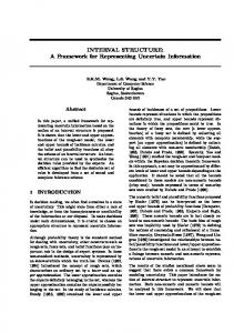
2.1 The Dependability Tree A precise and complete characterisation of dependability is given 1. by enumerating its basic properties or attributes, 2. by explaining what phenomena constitute potential impairments to it, and 3. by reviewing the scientific disciplines and the techniques that can be adopted as means for improving dependability. Attributes, impairments, and means can be globally represented into one picture as a tree, traditionally called the dependability tree [Lap95] (see Fig. 2.1). 11
CHAPTER 2. THE LAPRIE MODEL OF DEPENDABILITY
12
Figure 2.1: The dependability tree
2.1.1 Attributes of Dependability As already mentioned, dependability is a general concept that embraces a number of different properties. These properties correspond to different viewpoints from which the user perceives the quality of the offered service—in other words, for different users there will be in general different key properties corresponding to a positive assessment for the service:
Î Î
the property that addresses the readiness for usage, that has been termed as availability,
Î
the property that measures the continuity of service delivery, that has been termed reliability,
Î
the property expressing the reliance on the non-occurrence of events with catastrophic consequences on the environment, known as safety,
Î
the property that measures the reliance on the non-occurrence of unauthorised disclosure of information, i.e., confidentiality,
Î
the property that measures the reliance on the non-occurrence of improper alterations of information, that has been called integrity, the property that expresses the ability to undergo repairs and upgrades, that has been called maintainability.
These properties qualify dependability, and therefore are known as its attributes [Lap95]. A special combination of these attributes has been termed as security and defined as the conjoint requirement for integrity, availability, and confidentiality. A more formal definition exists for most of the above properties. Section 2.1.2 formally defines those attributes and quantities that are more pertaining to the rest of this dissertation, including availability, reliability, and maintainability.
2.1. THE DEPENDABILITY TREE
13
2.1.2 Formal Definitions This section defines a number of important measures of the quality of service of a system, including three of the attributes presented in 2.1.1 that are most relevant in what follows. 2.1.2.1 Reliability Reliability is defined as follows:
ÏÑÐ�ÒÓ@Ô�Ò Õ Öy×�Ø correct Ù ÒÓ@Ô�Ò ÚÛ
correct
Ù ÒÓ@Ô�ÒÓ�ÚÝÜMÔ
ÏÑÐ�ÒÓ@Ô�Ò Õ Þ Ù ÒÓ2Ô�Ò Ú
Þ
where “correct ” represents the event “the system provides its service during time interval ”, and is the conditional probability that the system will perform correctly throughout the interval , given that the system was performing correctly at time [Joh89]. Time is usually omitted and taken as the current time. The general notation for reliability is therefore . The negative counterpart of reliability, unreliability, is defined as , and represents the conditional probability that the system will perform incorrectly during the interval , given that the system was performing correctly at time . Unreliability is also known as the probability of failure, and quantity
ÏÑÐ�Ò Õ
Ò�Ó
Ù ÒÓ@Ô�Ò Ú
Ò�Ó
Ò&Ó
ß Ð�Ò ÕàÖ áãâäÏÑÐ�Ò Õ
�Ð Ò Õ � Ð Ò Q Õ æ Ö å ß fail åÒ
is the failure density function. If the failure rate of a system is assumed to be fixed, i.e., if the expected number of failures per a given period of time can be considered as constant, as it happens in the “useful life period” of electronic equipment, then it is possible to show [Joh89] that
ç
ÏÑÐ�Ò Õ Ö|è�éJê(ë¬ìíJî
The above equation is known as the exponential failure law. 2.1.2.2 Mean Time To Failure, Mean Time To Repair, and Mean Time Between Failures Mean Time to Failure (MTTF) is defined as the expected time that a system will operate before the occurrence of its first failure. More formally, it is the expected value of the time of failure, or, from probability theory,
�Ð Ò Õ ÒQÖäïñð ÏÑÐ�Ò Õ Ò�î � Ð Ò Õ Ò Q y Ö ñ ï ð Ò 0 å ß å fail å Ó Ó åÒ å If reliability obeys the exponential failure law with constant failure rate ç , then áî Ö � è J é ê Ò Ö ñ ï ð ¬ ë ì í å ç MTTF Ó Öyïñð Ò MTTF ëð
CHAPTER 2. THE LAPRIE MODEL OF DEPENDABILITY
14
Mean Time to Repair (MTTR) is defined as the average time required to repair a system. It is often specified by means of a repair rate , namely the average number of repairs that occur per time unit. If is a constant, MTTR is the inverse of repair rate. Mean Time Between Failures (MTBF) is the average time between any two consecutive failures of a system. This is slightly different from MTTF which concerns a system’s very first failure. The following relation holds:
ò
ò
MTBF
ó
MTTF
ô
MTTR
õ
As it is usually true that MTTR is a small fraction of MTTF, it is usually allowed to assume that MTBF MTTF.
ö
2.1.2.3 Availability Availability is defined as a function of time representing the probability that a service is operating correctly and is available to perform its functions at the instant of time [Joh89]. It is usually represented as function . Availability represents a property at a given point in time, whereas reliability concerns time intervals. These two properties are not to be mistaken with each other— a system might exhibit a good degree of availability and yet be rather unreliable, e.g., when inoperability is pointwise or rather short. Availability can be approximated as the total time that a system has been capable of supplying its intended service divided by the elapsed time that system has been in operation, i.e., the percentage of time that the system is available to perform its expected functions. The steady-state availability can be proven [Joh89] to be
÷
øúù�÷ û
ø�ü üýó
MTTF MTTF MTTR
ô
þ
2.1.2.4 Maintainability Maintainability is a function of time representing the probability that a failed system will be repaired in a time less than or equal to . It can be estimated as
÷
ò
ÿ ù�÷ û³ó������� ��
���
being the repair rate, assumed to be constant (see Sect. 2.1.2.2).
2.1.3 Impairments to Dependability Hardware and software systems must conform to certain specifications, i.e., agreed descriptions of the system response for any initial system state and input, as well as the time interval within which the response should occur. This includes a description of the functional behaviour of the system—basically, what the system is supposed to do, or in other words, a description of its service—and possibly a description of other, non-functional requirements. Some of these requirements may concern the dependability of the service.
2.1. THE DEPENDABILITY TREE
15
In real life, any system is subject to internal or external events that can affect in different ways the quality of its service. These events have been partitioned into three classes by their causeeffect relationship: depending on this, an impairment can be classified as a fault, an error, or a failure. When the delivered service of a system deviates from its specification, the user of the system experiences a failure. Such failure is due to a deviation from the correct state of the system, known as an error. That deviation is due to a given cause, for instance related to the physical state of the system, or to bad system design. This cause is called a fault. A failure of a system could give rise to an event that is perceived as a fault by the user of that system, bringing to a concatenation of cause-and-effects events known as the “fundamental chain” [Lap85]:
�
����� fault �
error
�
failure
�
fault
�
error
�
failure
� �����
(symbol “ ” can be read as “brings to”). Attributes defined in Sect. 2.1.1 can be negatively affected by faults, errors, and failures. For this reason, failures, errors, and faults have been collectively termed as the “impairments” of dependability. They are characterised in the following three paragraphs. 2.1.3.1 Failures System failures occur when the system does not behave as agreed in the system specifications. This can happen in many different ways [Cri91]: omission failures occur when an agreed reply to a well defined request is missing. The request appears to be ignored; timing failures occur when the service is supplied, though outside the real-time interval agreed upon in the specifications. This may occur when the service is supplied too soon (early timing failure), or too late (late timing failure, also known as performance failure); response failures happen either when the system supplies an incorrect output (in which case the failure is said to be a value failure), or when the system executes an incorrect state transition (state transition failure); crash failure is when a system continuously exhibits omission failures until that system is restarted. In particular, a pause-crash failure occurs when the system restarts in the state it had right before its crash, while a halting-crash occurs when the system simply never restarts. When a restarted system re-initialises itself wiping out the state it had before its crash, that system is said to have experienced an amnesia crash. It may also be possible that some part of a system’s state is re-initialised while the rest is restored to its value before the occurrence of the crash—this is called a partial-amnesia crash. Defining the above failure classes allows to extend a system’s specification—that is, the set of its failure-free behaviours—with failure semantics, i.e., with the failure behaviour that system is likely to exhibit upon failures. This is important when programming strategies for recovery after failure [Cri91]. For instance, if the service supplied by a communication system may delay
CHAPTER 2. THE LAPRIE MODEL OF DEPENDABILITY
16
transmitted messages but never lose or corrupt them, then that system is said to have performance failure semantics. If that system can delay and also lose them, then it is said to have omission/performance failure semantics. In general, if the failure semantics of a system allows it to exhibit a behaviour in the union of two failure classes and , then is said to have failure semantics. In other words, the “slash” symbol can be read as the union operator among sets. For any given it is possible to count the possible failure behaviours in a failure class. Let us call this function from the set of failure classes to integers. Then, given failure classes and ,
�
�
�
�
�����
� � ��������� �"!#�����%$&� �'!#����� �)(*�� �+�,�.-
�
�
�
�
�
�
�
Failure semantics can be partially ordered by means of function : given any two failure semantics and , then is said to exhibit a weaker (less restrictive) failure semantics than :
�����5/6�
�0/1� 2
�
����� �43%����� ��-
�
In particular . Therefore, the union of all possible failure classes represents the weakest failure semantics possible. If system exhibits such semantics, is said to have arbitrary failure semantics, i.e., can exhibit any failure behaviour, without any restriction. By its definition, arbitrary failure semantics is also weaker than arbitrary value failure semantics. This latter is also known as Byzantine failure semantics [LSP82]. In the case of stateless systems, pause-crash and halting-crash behaviours are subsets of omission failure behaviours [Cri91], so omission failure semantics is in this case weaker than pause-crash and halting-crash failure semantics. As clearly stated in [Cri91], it is the responsibility of a system designer to ensure that it properly implements a specified failure semantics. For instance, in order to implement a processing service with crash failure semantics, one can use duplication with comparison: two physically independent processors executing in parallel the same sequence of instructions and comparing their results after the execution of each instruction. As soon as a disagreement occurs, the system is shut down [Pow97]. Another possibility is to use self-checking capabilities. Anyway, given any failure semantics , it is up to the system designer to decide how to implement it, also depending on the designer’s other requirements, e.g., those concerning costs and expected performance. In general, the weaker the failure semantics, the more expansive and complex to implement it. Moreover, a weak failure semantics imply higher costs in terms of redundancy exhaustion (see Sect. 2.2) and, often, higher performance penalties. For this reason, the designer may leave the ultimate choice to the user—for instance, the designer of the Motorola C compiler for the PowerPC allows the user to choose between two different modes of compilation—the fastest mode does not guarantee that the state of the system pipeline be restored on return from interrupts [Sun96]. This translates into behaviours belonging to the partial-amnesia crash semantics. The other mode guarantees the non-occurrence of these behaviours at the price of a lower performance for the service supplied by that system—programs compiled with this mode run slower. Failures can also be characterised according to the classification in Fig. 2.2 [Lap95], corresponding to the different viewpoints of
�
�
2.1. THE DEPENDABILITY TREE
17
Figure 2.2: Failure classes.
7 7
failure domain (i.e., whether the failure manifests itself in the time or value domain),
7
failure perception (i.e., whether any two users perceive the failure in the same way, in which case the failure is said to be consistent, or differently, in which the failure is said to be inconsistent), and consequences on the environment. In particular a failure is said to be benign when consequences are of the same order as the benefits provided by normal system operation, while it is said catastrophic when consequences are incommensurably more relevant than the benefits of normal operation [Lap95].
Systems that provide a given failure semantics are often said to exhibit a “failure mode”. For instance, systems having arbitrary failure semantics (in both time and value domains) are called fail-uncontrolled systems, while those only affected by benign failures are said to be fail-safe systems; likewise, systems with halt-failure semantics are referred to as fail-halt systems. These terms are also used to express the behaviour a system should have when dealing with multiple failures—for instance, a “fail-op, fail-op, fail-safe” system is one such that is able to withstand two failures and then behaves as a fail-safe system [Rus94] (fail-op stands for “after failure, the system goes back to operational state”). Finally, it is worth mentioning the fail-time-bounded failure mode, introduced in [Cuy95], which assumes that all errors are detected within a predefined, bounded period after the fault has occurred. 2.1.3.2 Errors An error is the manifestation of a fault [Joh89] in terms of a deviation from accuracy or correctness of the system state. An error can be either latent, i.e., when its presence in the system has not been yet perceived, or detected, otherwise. Error latency is the length of time between the occurrence of an error and the appearance of the corresponding failure or its detection. 2.1.3.3 Faults A fault is a defect, or an imperfection, or a lack in a system’s hardware or software component. It is generically defined as the adjudged or hypothesised cause of an error. Faults can have their
CHAPTER 2. THE LAPRIE MODEL OF DEPENDABILITY
18
Figure 2.3: Laprie’s fault classification scheme.
origin within the system boundaries (internal faults) or outside, i.e., in the environment (external faults). In particular, an internal fault is said to be active when it produces an error, and dormant (or latent) when it does not. A dormant fault becomes an active fault when it is activated by the computation process or the environment. Fault latency is defined as either the length of time between the occurrence of a fault and the appearance of the corresponding error, or the length of time between the occurrence of a fault and its removal. Faults can be classified according to five viewpoints [Lap92, Lap95, Lap98]—phenomenological cause, nature, phase of creation or occurrence, situation with respect to system boundaries, persistence. Not all combinations can give rise to a fault class—this process only defines 17 fault classes, summarised in Fig. 2.3. These classes have been further partitioned into three “groups”, known as combined fault classes. The combined fault classes that are more relevant in the rest of the dissertation are now briefly characterised: Physical faults:
8
8
Permanent, internal, physical faults. This class concerns those faults that have their origin within hardware components and are continuously active. A typical example is given by the fault corresponding to a worn out component. Temporary, internal, physical faults (also known as intermittent faults) [BCDGG97]. These are typically internal, physical defects that become active depending on a particular pointwise condition.
2.1. THE DEPENDABILITY TREE
9
19
9
Permanent, external, physical faults. These are faults induced on the system by the physical environment. Temporary, external, physical faults (also known as transient faults) [BCDGG97]. These are faults induced by environmental phenomena, e.g., EMI.
Design faults:
9 9
Intentional, though not malicious, permanent / temporary design faults. These are basically trade-offs introduced at design time. A typical example is insufficient dimensioning (underestimations of the size of a given field in a communication protocol 1 , and so forth).
9
Accidental, permanent, design faults (also called systematic faults, or Bohrbugs): flawed algorithms that systematically turn into the same errors in the presence of the same input conditions and initial states—for instance, an unchecked divisor that can result in a division-by-zero error. Accidental, temporary design faults (known as Heisenbugs, for “bugs of Heisenberg”, after their elusive character): while systematic faults have an evident, deterministic behaviour, these bugs depend on subtle combinations of the system state and environment.
Interaction faults:
9 9
Temporary, external, operational, human-made, accidental faults. These include operator faults, in which an operator does not correctly perform his or her role in system operation.
9
1
Temporary, external, operational, human-made, non-malicious faults: “neglect, interaction, or incorrect use problems” [Sib98]. Examples include poorly chosen passwords and bad system parameter setting. Temporary, external, operational, human-made, malicious faults. This class includes the so-called malicious replication faults, i.e., faults that occur when replicated information in a system becomes inconsistent, either because replicates that are supposed to provide identical results no longer do so, or because the aggregate of the data from the various replicates is no longer consistent with system specifications.
A noteworthy example is given by the bad dimensioning of IP addresses. Currently, an IP address consists of four sections separated by periods. Each section contains an 8-bit value, for a total of 32 bits per address. Normally this would allow for more than 4 billion possible IP addresses—a rather acceptable value. Unfortunately, due to a lavish method for assigning IP address space, IP addresses are rapidly running out. A new protocol, IPv6 [HD95], is going to fix this problem through larger data fields (128-bit addresses) and a more flexible allocation algorithm.
CHAPTER 2. THE LAPRIE MODEL OF DEPENDABILITY
20
2.1.4 Means for Dependability Developing a dependable service, i.e., a service on which reliance can be placed justifiably, calls for the combined utilisation of a set of methods and techniques globally referred to as the “means for dependability” [Lap98]: fault prevention aims at preventing the occurrence or introduction of faults. Techniques in this category include, e.g., quality assurance and design methodologies; fault-tolerance groups methods and techniques to set up services capable of fulfilling their function in spite of faults; fault removal methods try to reduce the number, incidence, and consequences of faults. Fault removal is composed of three steps: verification, diagnosis and correction. Verification checks whether the system adheres to certain properties—the verification conditions— during the design, development, production or operation phase; if it does not, the fault(s) preventing these conditions to be fulfilled must be diagnosed, and the necessary corrections (corrective maintenance) must be made; fault forecasting investigates how to estimate the present number, the future incidence and the consequences of faults. Fault forecasting is conducted by evaluating the system behaviour with respect to fault occurrence or activation. Qualitatively, it aims at identifying, classifying and ordering failure modes or at identifying event combinations leading to undesired effects. Quantitatively, it aims at evaluating (in terms of probabilities) some of the attributes of dependability. Of the above mentioned methods, fault-tolerance represents the core tool for the techniques and tools presented in this dissertation. Therefore, it is discussed in more detail in Sect. 2.1.4.1. 2.1.4.1 Fault-Tolerance Fault-tolerance methods come into play the moment a fault enters the system boundaries. Its core objective is “preserving the delivery of expected services despite the presence of fault-caused errors within the system itself” [Avi85]. Fault-tolerance has its roots in hardware systems, where the assumption of random component failures is substantiated by the physical characteristics of the adopted devices [Rus94]. According to [AL81], fault-tolerance can be decomposed into two sub-techniques—error processing and fault treatment. Error processing aims at removing errors from the computational state (if possible, before failure occurrence). It can be based on the following primitives [Lap95]: Error detection which aims to detect the presence in the system of latent errors before they are activated. This can be done, e.g., by means of built-in self-tests or by comparison with redundant computations [Rus94].
2.1. THE DEPENDABILITY TREE
21
Error diagnosis i.e., assessing the damages caused by the detected errors or by errors propagated before detection. Error recovery i.e., the replacement of an erroneous state by an error-free state. This replacement takes one of the following forms: 1. Compensation, which means reverting the erroneous state into an error-free one exploiting information redundancy available in the erroneous state, predisposed, e.g., through the adoption of error correcting codes [Joh89]. 2. Forward recovery, which finds a new state from which the system can operate (frequently in degraded mode). This method only allows to recover from errors of which the damage can be anticipated 2 —therefore, this method is system dependent [LA90]. The main tool for forward error recovery is exception handling [Cri95]. 3. Backward recovery, which substitutes an erroneous state by an error-free state prior to the error occurrence. As a consequence, the method requires that, at different points in time (known as recovery points), the current state of the system be saved in some stable storage means. If a system state saved in a recovery point is error-free, it can be used to restore the system to that state, thus wiping out the effects of transient faults. For the same reason, this technique allows also to recover from errors of which the damage cannot or has not been anticipated. The need for backward error recovery tools and techniques stems from their ability to prevent the occurrence of failures originated by transient faults, which are many times more frequent than permanent faults [Rus94]. The main tools for backward error recovery are based on checkpoint-and-rollback [Dec96] and recovery blocks [Ran75] (see Sect. 3.1.2.1). Fault treatment aims at preventing faults from being re-activated. It can be based on the following primitives [Lap95]: Fault diagnosis i.e., identifying the cause(s) of the error(s), in location and nature, i.e. determining the fault classes to which the faults belong. This is different from error diagnosis; besides, different faults can lead to the same error. Fault passivation i.e., preventing the re-activation of the fault. This step is not necessary if the error recovery step removes the fault, or if the likelihood of re-activation of the fault is low enough. Reconfiguration updates the structure of the system so that non-failed components fulfil the system function, possibly at a degraded level, even though some other components have failed. 2
:
In general, program specifications are not complete: there exist input states for which the behaviour of the corresponding program has been left unspecified. No forward recovery technique can be applied to deal with errors resulting from executing on these input states. On the contrary, if a given specification is complete, that is, if each input state is covered in the set of all the standard and exceptional specifications for , and if is totally correct, i.e. fully consistent with what prescribed in , then is said to be robust [Cri95]. In this case forward recovery can be used as an effective tool for error recovery.
:
;
;
:
:
:
CHAPTER 2. THE LAPRIE MODEL OF DEPENDABILITY
22
2.2 Fault-Tolerance, Redundancy, and Complexity A well-known result by Shannon [SWS93] tells us that, from any unreliable channel, it is possible to set up a more reliable channel by increasing the degree of information redundancy. This means that it is possible to trade off reliability and redundancy of a channel. The author of this dissertation observes that the same can be said for a fault-tolerant system, because fault-tolerance is in general the result of some strategy effectively exploiting some form of redundancy—time, information, and/or hardware redundancy [Joh89]. This redundancy has a cost penalty attached, though. Addressing a weak failure semantics, able to span many failure behaviours, effectively translates in higher reliability—nevertheless, 1. it requires large amounts of extra resources, and therefore implies a high cost penalty, and 2. it consumes large amounts of extra resources, which translates into the rapid exhaustion of the extra resources. For instance, a well-known result by Lamport et al. [LSP82] sets the minimum level of redundancy required for tolerating Byzantine failures to a value that is greater than the one required for tolerating, e.g., value failures. Using the simplest of the algorithms described in the cited paper, a 4-modular-redundant (4-MR) system can only withstand any single Byzantine failure, while the same system may exploit its redundancy to withstand up to three crash faults—though no other kind of fault [Pow97]. In other words: After the occurrence of a crash fault, a 4-MR system with strict Byzantine failure semantics has exhausted its redundancy and is no more dependable than a nonredundant system supplying the same service, while the crash failure semantics system is able to survive to the occurrence of that and two other crash faults. On the other hand, the latter system, subject to just one Byzantine fault, would fail regardless its redundancy. Therefore, for any given level of redundancy, trading complexity of failure mode against number and type of faults tolerated may be considered as an important capability for an effective fault-tolerant structure. Dynamic adaptability to different environmental conditions 3 may provide a satisfactory answer to this need, especially when the additional complexity does not burden (and jeopardise) the application. Ideally, such complexity should be part of a custom architecture and not of the application. On the contrary, the embedding in the application of complex failure semantics, covering many failure modes, implicitly promotes complexity, as it may require the implementation of many recovery mechanisms. This complexity is detrimental to the dependability of the system, as it is in itself a significant source of design faults. Furthermore, the isolation of that complexity outside the user application may allow cost-effective verification, validation and testing. These processes may be unfeasible at application level. 3
The following quote by J. Horning [Hor98] captures very well how relevant may be the role of the environment with respect to achieving the required quality of service: “What is the most often overlooked risk in software engineering? That the environment will do something the designer never anticipated”.
2.3. CONCLUSIONS
23
The author of this dissertation conjectures that a satisfactory solution to the design problem of the management of the fault-tolerance code (presented in Sect. 1.1.2) may translate in an optimal management of the failure semantics (with respect to the involved penalties). The fault-tolerance linguistic structure proposed in Chapter 4 and following ones allows to solve the above problems exploiting its adaptability (A ).
2.3 Conclusions This chapter has introduced the reader to Laprie’s model of dependability describing its attributes, impairments, and means. The central topic of this dissertation, fault-tolerance, has also been briefly discussed. The complex relation between the management of fault-tolerance, of redundancy, and of complexity, has been pointed out. In particular, a link has been conjectured between attribute A and the dynamic ability to trade off the complexity of failure mode against number and type of faults being tolerated.
24
CHAPTER 2. THE LAPRIE MODEL OF DEPENDABILITY
Chapter 3 Current Approaches for Application-Level Fault-Tolerance One of the conclusions drawn in Chapter 1 is that the system to be made fault-tolerant must include provisions for fault-tolerance also in the application layer of a computer program. In that context, the problem of which system structure to use for ALFT has been proposed. This chapter provides a critical survey of the state-of-the-art on embedding fault-tolerance means in the application layer. According to the literature, at least six classes of methods, or approaches, can be used for embedding fault-tolerance provisions in the application layer of a computer program. This chapter describes these approaches and points out positive and negative aspects of each of them with respect to the structural attributes defined in Sect. 1.1.2 and to various application domains. A non-exhaustive list of the systems and projects implementing these approaches is also given. Conclusions are drawn in Sect. 3.6, where the need for more effective approaches is recognised. Two of the above mentioned approaches derive from well-established research in software fault-tolerance—Lyu [Lyu98b, Lyu96, Lyu95] refers to them as single-version and multipleversion software fault-tolerance. They are dealt with in Sect. 3.1. A third approach, described in Sect. 3.2, is based on metaobject protocols. It is derived from the domain of object-oriented design and can also be used for embedding services other than those related to fault-tolerance. A fourth approach translates into developing new custom high-level distributed programming languages or enhancing pre-existent languages of that kind. It is described in Sect. 3.3. A structuring technique called aspect-oriented programming, is reported in Sect. 3.4. Finally, Sect. 3.5 describes an approach, based on a special recovery task monitoring the execution of the user task.
3.1 Single- and Multiple-Version Software Fault-Tolerance A key requirement for the development of fault-tolerant systems is the availability of replicated resources, in hardware or software. A fundamental method employed to attain fault-tolerance is multiple computation, i.e., -fold ( ) replications in three domains:
”) in general will not be supplied.
CHAPTER 5. A DISTRIBUTED ARCHITECTURE BASED ON 6�7!8
100 A RIEL’s guards.
An excerpt of the context-free grammar rules for guards follows:
status
:FAULTY 9 RUNNING 9 REBOOTED 9 RESTARTED 9 TRANSIENT ;
entity
:GROUP
expr
:status entity 9 ’(’ expr ’)’ 9 expr AND expr 9 expr OR expr 9 NOT expr 9 ERRN ’(’ entity ’)’ comp NUMBER 9 PHASE ’(’ entity ’)’ comp NUMBER ;
comp
:EQ
9
9
NODE
NEQ
9
GT
9
9
STARTED
9
ISOLATED
9
TASK ;
GE
9
LT
9
LE ;
The following conditions and values have been foreseen: Faulty. This is true when an error notification related to a processing node, a group of tasks, or a single task, can be found in the TIRAN DB. Running. True when the corresponding entity is active and no error has been detected that regards it. Rebooted (only applicable to nodes). This means that a node has been rebooted at least once during the run-time of the application. Started (not applicable to nodes). This checks whether a waiting task or group of task has been started. Isolated. This clause is true when its argument has been isolated from the rest of the application through a deliberate action. Phase (only applicable to tasks). It returns the current value of an attribute set by any task via the public function RaiseEvent. This value is forwarded to the BB to represent its current “phase” or state (e.g., an identifier referring to its current algorithmic step, or the outcome of a test or of an assertion). For instance, a voting task could inform the BB that it has completed a given algorithmic step by setting a given integer value after each step (this approach is transparently adopted in the EFTOS voting tool and is described in more detail in [DFDL98c]). Recovery block tests can take advantage of this facility to switch back and try an alternate task when a primary one sets a “failure” phase or when a guarding watchdog expires because a watched task sent it no signs of life. This condition returns an integer symbol that can be compared via C-like arithmetic operators. Restarted (not applicable to nodes). This returns the number of times a given task or group has been restarted. It implies started.
5.3. THE ARIEL CONFIGURATION AND RECOVERY LANGUAGE
101
Transient is true when an entity has been detected as faulty and the current assessment of the : -count fault identification mechanism (see Sect. 5.2.4.2) is “transient”. It implies faulty. Furthermore, it is possible to query the number of errors that have been detected and pertain to a given entity. Complex guards can be built via the standard logic connectives and parentheses. As an example, the following guard: FAULTY TASK ; MASTER < AND ERRN(TASK ; MASTER < ) > 10 AND RESTARTED TASK ; MASTER < . checks whether the three conditions: =
=
the task, the unique-id of which is the value of the symbolic constant MASTER, has been detected as faulty;
=
more than 10 errors have been associated to that task; that task has been restarted,
are all true. A RIEL ’s actions. “Actions” can be attached to the THEN or ELSE parts of a section. In the current implementation of the language, these actions allow to start, isolate, restart, terminate a task or a group of tasks, to isolate or reboot a node, to invoke a local function. Moreover, it is possible to multicast messages to groups of tasks and to purge events from the DB. An excerpt of the context-free grammar for A RIEL’s actions follows: actions
:> actions action ;
action
:> >
section recovery action ;
recovery action :> STOP entity ISOLATE entity > START entity > REBOOT entity > RESTART entity > ENABLE entity > SEND NUMBER TASK > > SEND NUMBER GROUP WARN entity ( condition ) > REMOVE PHASE entity FROM ERRORLIST > REMOVE ANY entity FROM ERRORLIST ;
CHAPTER 5. A DISTRIBUTED ARCHITECTURE BASED ON ?�@!A
102 B B
condition :
CALL NUMBER CALL NUMBER ’(’ list ’)’ ERR NUMBER entity ;
As suggested in Sect. 4.2.3.2, a special case of action is a section, i.e., another guarded action. This allows to specify hierarchies (trees) of sections such that, during the run-time evaluation of the recovery strategies, a branch is only visited when its parent clause has been evaluated as true. In the current, prototypic implementation, the following actions have been foreseen: Stop terminates a task or a group of tasks, or initiates the shutdown procedure of a node 8 . Isolate prevents an entity to communicate with the rest of the system 9 . Reboot reboots a node (via the TIRAN Reboot Node BT). Start spawns (or, in static environments, awakes) a task or a group. Restart is reverting a task or group of tasks to their initial state or, if no other means are available, stopping that entity and spawning a clone of it. Enable awakes a task or group, or boots a node. Send multicasts (or sends) signals to groups of tasks (or single tasks). Warn informs a task or group of tasks that an error regarding an entity has been detected. Action “WARN C ” is equivalent to action “SEND D WARN EFC ” Remove purges records from the section of the DB collecting the errors or the phases of a given entity. Custom actions and conditions may be easily added to the grammar of ARIEL 10 . When actions are specified, it is possible to use meta-characters to refer implicitly to a subset of the entities involved in the query. For instance, when the first atom specifies a group of tasks, 8
These services are obtained via specific function calls to the level-1.2 BTs (see the edge from RINT to those BTs in Fig. 5.1). Such BTs, in turn, can either execute, through the BSL, a kernel-level function for stopping processes— if available—or send a termination signal to the involved processes. The actual choice is taken transparently, and RINT only calls one or more times either a TIRAN Stop Task or a TIRAN Stop Node function. 9 This service is obtained as described in the previous footnote. Depending on the characteristics of the adopted platform, isolation can be reached either through support at the communication driver or kernel level, or as follows: when a task opens a connection, a reference to a given object describing the connection is returned to both the user code and the local component of the BB. Action ISOLATE simply substitutes this object with another one, the methods of which prevent that task to communicate. This explains the third application-specific assumption of Sect. 4.1.2. 10 For instance, condition “DEADLOCKED” and action “CALL” (see Appendix C) were added to test the inclusion in ARIEL, respectively, of a provision for checking whether two tasks are in a deadlock (see [EVM G 98] for a description of this provision) and of a hook to the function call invocation method. These two provisions were easily included in the grammar of ARIEL.
5.3. THE ARIEL CONFIGURATION AND RECOVERY LANGUAGE
103
IF [ FAULTY (GROUP H My Group I ) AND NOT TRANSIENT (GROUP H My Group I ) ] THEN STOP TASK@ SEND H DEGRADE I TASK J FI
Table 5.4: This section queries the state of group K My Group L and, if any of its tasks have been detected as affected by a permanent or intermittent fault, it stops those tasks and sends a control message to those considered as being correct so that they reconfigure themselves gracefully degrading their overall service.
STOP TASK@1 means “terminate those tasks, belonging to the group mentioned in the first atom of the guard, that fulfil that condition”, while WARN TASK M 2 means “warn those tasks, belonging to the group mentioned in the second atom of the guard, that do not fulfil the second condition”. If one does not specify any number, as in STOP TASK@, then the involved group of tasks is the one that fulfils the whole clause. Table 5.4 shows an example of usage of this feature. Metacharacter “star” (*) can be used to refer to any task, group, or processing node in the system. Actions like STOP TASK* or STOP GROUP* are trapped by the translator and are not allowed. Metacharacter “dollar” ($) can be used to refer in a section to an entity mentioned in an atom. For instance, STOP GROUP$2 means “stop the group mentioned in the second atom of the clause”. The whole context-free grammar of ARIEL is provided in Appendix C. 5.3.3.1 Compile-time Support for Error-Recovery Once fed with a recovery script, the art translator produces a binary pseudo-code, called the r-code. In the current version, this r-code is written in a binary file and in a C header file as a statically defined C array, as in Table 5.5. As can be seen in that table, the r-code is made of a set of “triplets” of integers, given by an opcode and two operands. These are called “r-codes”. This header file needs to be compiled with the application. Run-time error recovery is carried out by the RINT module, which basically is an r-code interpreter. This module and its recovery algorithm are described in the following section. The rest of this section describes how to translate an ARIEL script into the r-code. Within this section and the following one the simple script of Table 5.6 will be used as an example. The following scenario is assumed: a triple modular redundancy (TMR) system consisting of three voting tasks, identified by integers {VOTER1}, {VOTER2}, and {VOTER3} is operating. A fourth task, identified as T{SPARE}, is available and waiting. It is ready to take over one of the voting tasks should the latter fail. The failed voter signals its state to the backbone by entering phase HAS_FAILED through some self-diagnostic module (e.g., assertions or controlflow monitoring). The spare is enabled when it receives a {WAKEUP} message and it requires the identity of the voter it has to take over. Finally, it is assumed that once a voter receives a control message with the identity of the spare, it has to initiate a reconfiguration of the TMR
104
CHAPTER 5. A DISTRIBUTED ARCHITECTURE BASED ON N�O!P
/************************************************************* * * * Header file trl.h * * * * Hardwired set of r-codes for Ariel file ariel * * Written by art (v2.0g 03-Aug-2000) on Fri Aug 18 2000 * * (c) Katholieke Universiteit Leuven 1999, 2000. * * * *************************************************************/ #ifndef _T_R_L__H_ #define _T_R_L__H_ #include "rcode.h" #define RCODE_CARD 15 /* total number of r-codes */ rcode_t rcodes[] = { /*line#*/ /* opcode */ /*0*/ { R_INC_NEST, /*1*/ { R_STRPHASE, /*2*/ { R_COMPARE, /*3*/ { R_FALSE, /*4*/ { R_STOP, /*5*/ { R_PUSH, /*6*/ { R_SEND, /*7*/ { R_PUSH, /*8*/ { R_SEND, /*9*/ { R_PUSH, /*10*/ { R_SEND, /*11*/ { R_PUSH, /*12*/ { R_SEND, /*13*/ { R_DEC_NEST, /*14*/ { R_OANEW, /*15*/ { R_STOP, };
/* operand 1 */ -1, 0, 1, 10, 18, 18, 18, 0, 18, 3, 18, 3, 18, -1, 1, -1,
/* operand 2 */ -1 }, -1 }, 9999 }, -1 }, 0 }, -1 }, 3 }, -1 }, 3 }, -1 }, 1 }, -1 }, 2 }, -1 }, -1 }, -1 },
Table 5.5: The beginning of header file trl.h, produced by art specifying option “-s”. Array rcodes is statically initialised with the r-code translation of the recovery strategy in the ARIEL script.
such that the failed voter is switched out of and the spare is switched in the system. Table 5.6 shows a recovery section that specifies what to do when task {VOTER1} fails. The user needs to supply a section like the one in lines 8–12 for each voting task. Another, more concise method based on defining a group of tasks (as in line 23 of Table 5.2) is discussed in Sect. 7.2.2.4.
5.3. THE ARIEL CONFIGURATION AND RECOVERY LANGUAGE 1
INCLUDE "my definitions.h"
2 3 4 5
TASK TASK TASK TASK
6 7 8
IF [ PHASE (T Q VOTER1 R ) == THEN STOP T Q VOTER1 R
Q
Q
Q
Q
105
VOTER1 R IS NODE Q NODE1 R , TASKID Q VOTER1 R VOTER2 R IS NODE Q NODE2 R , TASKID Q VOTER2 R VOTER3 R IS NODE Q NODE3 R , TASKID Q VOTER3 R SPARE R IS NODE Q NODE4 R , TASKID Q SPARE R
9 10
SEND SEND
Q
11 12 13 FI
SEND SEND
Q
Q
HAS FAILED R
]
WAKEUP R T Q SPARE R VOTER1 R T Q SPARE R
Q
Q
SPARE R SPARE R
T Q VOTER2 R T Q VOTER3 R
Table 5.6: Another excerpt from a recovery script: after the declarative part, a number of “sections” like the one portrayed in here can be supplied by the user.
Once the specification has been completed, the user can translate it, by means of the art program, into a pseudo-code whose basic blocks are the r-codes (see Table 5.7). A textual representation of the r-codes is also produced (see Table 5.8). Other than syntax errors, art catches a number of semantical inconsistencies which are reported to the user—as an example, a non-sense request, such as asking the phase of a node, gives rise to the following response: bash-2.02$ art -i .ariel -s Ariel translator, v2.0f 25-Jul-2000, (c) K.U.Leuven 1999, 2000. Parsing file .ariel... Line 76: semantical error: Can only use PHASE with tasks if-then-else: ok ...done (85 lines.) 1 error detected --- output rejected.
5.3.3.2 The ARIEL Recovery Interpreter This section briefly describes the ARIEL recovery interpreter, RINT. Basically RINT is a virtual machine executing r-codes. Its algorithm is straightforward: each time a new error or burst of errors is detected, S S
it executes the r-codes one triplet at a time; if the current r-code requires accessing the DB, a query is executed and the state of the entities mentioned in the arguments of the r-code is checked;
106
CHAPTER 5. A DISTRIBUTED ARCHITECTURE BASED ON T�U!V
bash-2.02$ art -i ariel -v -s Ariel translator, v2.0g 03-Aug-2000, (c) K.U.Leuven 1999, 2000. Parsing file ariel... [ Including file ‘my_definitions.h’ ...9 associations stored. ] substituting {VOTER1} with 0 substituting {NODE1} with 1 substituting {VOTER2} with 1 substituting {NODE2} with 2 substituting {VOTER3} with 2 substituting {NODE3} with 3 substituting {SPARE} with 3 substituting {NODE4} with 4 substituting T{VOTER1} with T0 substituting {HAS_FAILED} with 9999 substituting {WAKEUP} with 18 substituting T{SPARE} with T3 substituting T{VOTER2} with T1 substituting T{VOTER3} with T2 if-then-else: ok ...done (17 lines in 0.02 CPU secs, or 850.000 lines per CPU sec.) Output written in file .rcode. Tasks written in file TaskTable.csv. Preloaded r-codes written in file trl.h. Time-outs written in file timeouts.h. Identifiers written in file identifiers.h. Table 5.7: The art program translates the section mentioned in Table 5.6 into r-codes. The “-i” option is used to specify the input filename, “-v” sets the verbose mode, while “-s” allows to create three header files containing, among other things, an array of pre-loaded r-codes (see Table 5.5).
W
if the current r-codes requires executing actions, a request for execution is sent to the BB.
RINT plays an important role within the T�UXV architecture—its main objective is establishing and managing a causal connection between the entities of the A RIEL language (identifiers of nodes, tasks, and groups of tasks) and the corresponding components of the system and of the target application. This causal connection is supported by the BB and its DB. In particular, each atom regarding one or more entities is translated at run-time into one or more DB queries. Under the hypothesis that the DB reflects—with a small delay—the actual state of the system, the truth value of the clauses on the entities of the language will have a large probability to tally with the truth value of the assertions on the corresponding components of the system. Furthermore, by means of RINT, symbolic actions on the entities are translated into actual commands on the components. These commands are then managed by the BB as described in Fig. 5.7.
5.3. THE ARIEL CONFIGURATION AND RECOVERY LANGUAGE
107
Art translated Ariel strategy file: .... ariel into rcode object file : ............... .rcode line rcode opn1 opn2 ---------------------------------------------00000 SET_ROLE 0 Manager 00001 SET_ROLE 1 Assistant 00002 SET_ROLE 2 Assistant 00003 SET_ROLE 3 Assistant 00004 IF 00005 STORE_PHASE... Thread 0 00006 ...COMPARE == 9999 00007 FALSE 10 00008 STOP Thread 0 00009 PUSH... 18 00010 ...SEND Thread 3 00011 PUSH... 0 00012 ...SEND Thread 3 00013 PUSH... 3 00014 ...SEND Thread 1 00015 PUSH... 3 00016 ...SEND Thread 2 00017 FI 00018 ANEW_OA_OBJECTS 1 00019 STOP
Table 5.8: A textual representation of the r-code produced when translating the recovery section in Table 5.6.
The RINT task is available and disabled on each BB assistant while it is enabled on the BB manager. Only one execution process is allowed. RINT has the architecture of a stack-based machine—a run-time stack is used during the evaluation of clauses. In a future release of RINT, the run-time stack shall also be used as a means for communicating information between actions. For any r-code being executed, a message will be broadcast to the non-faulty assistants. Next rcode will only be executed when all the non-faulty assistants acknowledge the receipt of this message and update their stack accordingly. This allows to maintain a consistent copy of the current status of the run-time stack on each assistant. Should the manager fail while executing recovery, the new manager would then be able to continue recovery seamlessly, starting from the last r-code executed by the previous manager.
Chameleon. It is worth noting how some of the assumptions as well as some of the architectural solutions adopted in the TIRAN prototype and in its EFTOS predecessor have been recently adopted in a system called Chameleon [KIBW99]. This system uses a set of basic tools (called
108
CHAPTER 5. A DISTRIBUTED ARCHITECTURE BASED ON Y�Z![
armors) and a distributed component, hierarchically structured into managers and non-managers. These architectural solutions were adopted independently. No configuration nor any linguistic support to error recovery is currently part of Chameleon.
5.4 Conclusions The feasibility of an architecture supporting the recovery language approach for dependablesoftware engineering has been proved by describing the TIRAN framework, and in particular the TIRAN backbone and the configuration and recovery language ARIEL. This language and its runtime system provide the user with a fault-tolerance linguistic structure that appears to the user as a sort of second application-layer especially conceived and devoted to address the error recovery concerns. The strategies and the algorithms of the TIRAN framework have been also described. Next chapters complement this one by focusing on the effectiveness of this architecture.
Chapter 6 Using the Recovery Language Approach This chapter focuses on some examples of practical use of the \^]!_ architecture described in Chapter 5. Next chapter complements this one by focusing on the assessment of some of the elements of that architecture. As a matter of facts, an exhaustive analysis and assessment of an ALFT approach is a research activity that requires both serious usability studies as the approach matures and the analysis of many diverse real-life case studies—as it has been observed by the authors of the AOL approach what concerns the systems based on their approach [LVL00]. Hence, a complete and detailed evaluation for a large and complex architecture such as the TIRAN one, in its current prototypic state, is out of the scope of this dissertation. The case studies described in this chapter, as well as the architectural components evaluated in the next one, provide the reader with an idea of the class of applications that \`]X_ may tackle well and of the reasons behind these results, and as such it may be considered as a first effort towards a complete characterisation and evaluation of the \ ] _ approach. Further experimentation will also be carried out in the framework of a new ESPRIT project that is currently being evaluated for acceptance and financing 1 . A first case study is given by one of the pilot applications of the EFTOS project: the GLIMP software, embedded into the Siemens Integrated Mail Processor. It is described in Sect. 6.1, and focuses on the SC attribute and on performance issues. Section 6.2 describes how \`]!_ may be used to further improve the dependability of the class of applications that adopt NVP as their main fault-tolerance provision. It is shown how it is possible to exploit \a]!_ in order to enhance the TIRAN distributed voting tool described in Sect. 5.2.3 and attain both location transparency and replication transparency. Section 6.3 reports on the current use that is being made of ARIEL in an industrial application at ENEL in the framework of the TIRAN project. Section 6.4 shows how \ ] _ can be used to enhance the capabilities of the TIRAN basic 1
A proposal for a project called DepAuDE has recently passed the first steps towards official acceptance and financing. DepAuDE stands for “Dependability for embedded Automation systems in Dynamic Environments with intra-site and inter-site distribution aspects”. Aim of the project is to develop an architecture and methodology to ensure dependability for non-safety critical, distributed, embedded automation systems with both IP (inter-site) and dedicated (intra-site) connections. Dynamic behaviour of the systems is also required to accommodate for remote diagnosis, maintenance or upgrades.
109
110
CHAPTER 6. USING THE RECOVERY LANGUAGE APPROACH
Figure 6.1: The IMP system.
tools in a straightforward way. In particular, a strategy is described, devised at CESI and ENEL, which exploits the availability of a number of processing nodes in order to obtain high-safety or high-availability watchdogs from multiple instances of the simple, node-local TIRAN watchdog. Section 6.5 concludes the chapter summarising the positive aspects of b^c!d in the reported case studies.
6.1 A Case Study: The Siemens Integrated Mail Processor A first case study deals with an application in the industrial automation domain: an automatic mail sorting system developed by Siemens, the Integrated Mail Processor (IMP) [Ele00], is described. Figure 6.1 draws a typical configuration of the IMP. Such system may be defined as an integrated system for automated letter sorting designed to operate at country-level—according to Siemens, “the latest innovation in the automation of letter sorting”, combining the processing steps of several individual machines, from pre-processing, to reading and encoding, and up to sorting. Conceived and developed in close cooperation with one of the largest European postal services, the IMP is designed to avoid any manual handling and to ensure that no machinable mail is rejected under normal operating conditions. This section: e e
First introduces the class of problems addressed by IMP (in Sect. 6.1.1).
e
Then, in Sect. 6.1.2 and 6.1.3, it describes the hardware and software structures of a version of IMP, based on the Parsytec CC system, which has been subject of investigation during project EFTOS.
e
Next, Sect. 6.1.4 describes the main design requirements of IMP related to both real-time and dependability. Section 6.1.5 finally describes how the b results were obtained.
c d
approach was used in this case study and what
6.1. A CASE STUDY: THE SIEMENS INTEGRATED MAIL PROCESSOR
111
Figure 6.2: General Structure of Automatic Letter Sorting.
The main reference for this section is [BGB f 96]. In particular, all figures related to realtime, throughput, and dependability requirements for the described application are from the cited document.
6.1.1 Automatic Mail Sorting Machines Automatic Mail Sorting machines are used by many postal services all over the world to optimise the delivery of letters, flats, and packets. Typically, they must be able to transport and sort up to 36000 letters per hour. The main components of an automatic mail sorting machine are the transport machine, the scanner, the address reader (or OCR, i.e., Optical Character Recognition module), and the mechanical sorter. Today OCRs are able to recognise more than 90% of machine printed addresses with error rates less than 1%. The general structure of a typical sorting automation is illustrated in Figure 6.2. The OCR has to extract the address information from the mail piece image. A strong requirement for the OCR is that the address information must arrive at the sorter within the time interval given by the mail transport between scanner and sorter, otherwise the mail piece would be rejected. The required performance calls for a solution based on high-performance computing technology. The actual hardware structure adopting this technology is described in 6.1.2. Two main parts can be distinguished in the OCR software: a control module and the algorithmic modules. g
The control module is responsible for the correct collaboration of all algorithmic modules. Part of its task is to detect anomalous behaviour and take appropriate actions in such a case. As an example of this, it supervises the deadlines imposed by the rate at which letters are provided given by the physical transport characteristics of the system. In case of breaking of deadlines, corrective actions are required.
112
CHAPTER 6. USING THE RECOVERY LANGUAGE APPROACH
Figure 6.3: Schematic Data Flow of Image Processing. h
The algorithmic modules are responsible for the recognition task. They are purely dataflow driven and are not affected by modifications of the control software (and vice-versa).
During the EFTOS project, a specific functional part of the recognition module has been subject to investigation—the GLIMP (Gray Level IMage Processing) package. The purpose of GLIMP is to analyse the images of the scanned letters according to their various regions of interest (ROIs). From the mail sorting point of view, the most important ROI is clearly the address, however other ROIs located on the envelope of a letter are very important to the postal services (for example, for purposes of revenue protection and fraud detection, it is required to find and classify the stamp or the meter mark of the letter). Other labels indicate registered mail or foreign mail. The task of this ROI-analysis sub-system is performed in parallel in order to meet the real-time constraints of the sorting system. The global data flow can be described by the scheme of Fig. 6.3. The raw image of the scanner is fed into two image paths, one processing the image towards binarisation, the other one providing the ROI-analysis of the image, that execute in parallel. The results of this analysis is then used to extract the relevant parts of the image from the binarised image. Only these parts are further transmitted to the character recognition system. The second output of the ROI-analysis is the classification result, e.g. the value of a recognised stamp, or the presence and position of certain labels. These results are transmitted to the machine control (MC) in order to initiate special processing of the respective mail piece in the sorting system.
6.1.2 Hardware Structure The ROI-analysis of the mail piece images is performed in the original scanned grey level image. It is realised on a hardware platform physically separated from the recognition system. The implementation addressed in EFTOS and reported herein is based on the Parsytec CC system. As mentioned before, the CC is a MIMD supercomputer based on the 133-MHz PowerPC processor. This system hosts two types of nodes—the so-called I/O nodes, that communicate with external
6.1. A CASE STUDY: THE SIEMENS INTEGRATED MAIL PROCESSOR
113
Figure 6.4: Hardware Architecture of Image Processing Sub-System.
devices via a PCI bus, and the so-called compute nodes, purely devoted to processing. Both nodes communicate with each other via HS-links (high-speed links). The interfaces between the CC and the rest of the system is realised by PCI plug-in boards and via an Ethernet connection. A simple representation of the hardware architecture can be seen in Fig. 6.4. The images generated in the scanner are stored in an appropriate number of image buffers. The PCI bus interface of the I/O-node allows the images to be read into the system. Further distribution of parts of the images towards the compute node is realised via the HS-link connections. The compute nodes execute the algorithms for image processing and classification of the region of interest. The results of the analysis are passed on to the recognition system across the second I/O node and its PCI interface. The overall machine control interacts with the ROI-analysis system via an Ethernet connection.
6.1.3 Software Structure The overall software structure is completely data driven. An initial process, the Image Dispatcher (ID), receives parts of the images (regions) from the image buffer on request. Along with the image data comes a Region Descriptor (RD) indicating the type of the region. Both information is then distributed to a farm of algorithmic worker processes (AW) doing the image processing and classification algorithms. The distribution is controlled by the ID process according to some appropriate load balancing heuristics. The results of the AWs are collected in a Result Manager (RM) process. Once all relevant results belonging to a mail piece are available at the RM, it forwards them to the MC (machine control) and releases the images at the ID. The process graph of the software is depicted in Fig. 6.5.
114
CHAPTER 6. USING THE RECOVERY LANGUAGE APPROACH
Figure 6.5: Software Process Graph.
6.1.4 Design Requirements The overall performance characteristics of the mail sorting system vary according to the different customer requirements. The peak throughput requirements that had to be met at the time were in the order of 40000 mail pieces per hour. This means that the machine had to process about 11 mail pieces each second on the average. However, the mechanical transport of the mail pieces through the sorting machine is setting the upper limit for throughput. Transport speeds of several metres per second were achieved; higher speeds increase the probability of damaging the mail pieces. Beside the requirements for throughput, further boundary conditions influence the real-time behaviour of the system. In on-line mail sorting systems, the mail pieces are continuously moving through the system from the feeder to the final sorter bin2 . This means that each processing stage has to produce its results within some given amount of time. For example, the address recognition result needs to be available before the mail piece physically arrives at the sorter entry. The time each processing stage needs requires for an expensive mechanical storage line. The total latency of a mail piece in the complete sorting system is in the order of 10–20 seconds. For the ROI-analysis module investigated in EFTOS, i.e., GLIMP, the allowed latency time is in the order of one second. Dependability requirement for such a system include: i i
minimising the failures of the system;
2
confining the effects of errors through graceful degradation, avoiding as much as possible
Or to a so-called “unsorted bin”, in case of occasional failures of the classification algorithms.
6.1. A CASE STUDY: THE SIEMENS INTEGRATED MAIL PROCESSOR
115
total system failures and allowing operability at reduced throughput. j
In the event of total system failures due to unforeseen situations, i.e., a power failure, the recovery times must be kept to a minimum.
In GLIMP, the algorithms of the image analysis are implemented as distributed software processes communicating with each other and with the rest of the system. The input to GLIMP is originating from a piece of hardware (image buffer, filled by the scanner, triggered by the mechanical letter movement) with strict real-time requirements, while the output is sent down a TCP/IP Ethernet connection, which is not real-time. The most frequent problems with the realisation of the ROI-analysis are caused by unstable behaviour of the software processes. Dealing with real-life images means processing of unknown data with unpredictable properties. As mentioned in Sect. 1.1.1.3, given the amount of software complexity and the requirement of reduced development cycle times of nowadays’ software, the incremental process of software testing is an activity that can never be comprehensive at justifiable costs. Hence, data induced malfunctioning of the software may cause a software process to hang up 3 . One possible consequence of this is that a real-time deadline is missed. However, another consequence could be that a second process waiting for communication with this faulty process also gets stuck. In this way, the error condition can propagate through the whole system. Another effect of a data induced error may be the corruption of memory on the processor by writing outside of the processes address space. In this way other processes running on the same processor might be also corrupted by the faulting process. The occurrence of data induced software errors cannot be completely avoided. In the operational environment of the mail sorting, it is acceptable to lose the processing of one mail piece, but it is not acceptable that one faulty mail piece causes subsequent faults resulting in the loss of more mail pieces. Hence, it is important to detect errors as they occur, to confine them in a limited area, and to recover from the error as quick as possible.
6.1.5 Results Obtained and Lessons Learned The author of this dissertation and two colleagues of the ACCA Division had the possibility to work with the actual GLIMP libraries and to embed it into the so-called EFTOS Vertical Integration Test Application (VITA) —a farmer worker application developed by the colleagues of the National Technical University of Athens and used within EFTOS in order to exercise and test different demonstrations. This test application played the role of the control module, while the actual GLIMP libraries were used for the algorithmic modules. The VITA/GLIMP application was successfully demonstrated at one of the EFTOS review meetings. The enhanced version was simply the combination of GLIMP with the VITA, which in turn used a watchdog process, the prototypic backbone component developed in EFTOS and a few other ancillary codes. The watchdog informed the backbone of errors concerning the GLIMP processes. On receipt of such messages, the backbone automatically stopped and restarted the watched processes. In case of node crashes affecting both watched tasks and watchdogs, it was the backbone that detected such event by means of a variant of the AMS algorithm described in 3
The GLIMP workers have performance/crash failure semantics.
116
CHAPTER 6. USING THE RECOVERY LANGUAGE APPROACH
Sect. 5.2.4.14 . The performance overhead for the overall system with respect to the unmodified Siemens application was of about 15%. The increase of the binary size was of approximately 500 kilobytes. This quantity includes the codes of: the backbone, the watchdog, the VITA, and an ancillary code for communication management. The code intrusion in the VITA was limited to the code to configure and manage the watchdog (no configuration language was available in EFTOS). Error recovery produced no code intrusion, because a simple recovery action had been hardwired in the EFTOS backbone, hence outside the user application (the VITA). No amount of code was intruded in the GLIMP libraries, which were only available in the form of object code. Fast reboot and task restart were obtained through specific kernel-level provisions made available by Parsytec on their CC system. From the point of view of the structural attributes defined in Sect. 1.1.2, one can conclude that it was possible to obtain an optimal degree of SC and SA . Obtained results [Tea98] have been encouraging: the resulting application, run on a 2-node system, was able to tolerate process failures and node crash failures triggered by software fault injection, but also to revert to full throughput mode at the end of error recovery. Another version of the VITA, mimicking the original OCR control module but exploiting no fault-tolerance provisions, halved the system throughput when a first fault was injected, and stopped the system functions on the second injection. Indeed, GLIMP provides us with an example of a class of applications that well exploit the current properties of our first k`lXm prototype—the class of n n
parallel or distributed industrial automation applications,
n
with real-time requirements such that violations of the agreed deterministic timing behaviour are acceptable at error recovery time,
n
written in a procedural language such as C,
n
structured as a farmer-worker application, with a stateless worker process.
The case study reported so far taught us that, at least for this class, it is possible to make effective use of kal!m in order to increase both service throughput and dependability with minimal effort in terms of development costs and time. In particular, k l m can be qualitatively assessed as reaching very good values for properties such as SC and SA . On the contrary, with respect to the structural attributes, all the ALFT structures reviewed in Sect. 3 either do not address this class of applications or they would require a complete rewriting of the application in order to obtain similar results. This happens also because GLIMP is an example of those applications that may be called company asset codes—longly-run, longly-tested, large applications typically written in a procedural (non-object-oriented) standard language. These hypotheses forbid the adoption of approaches such as MV, AOP, MOP, and the adoption of ad-hoc programming languages. The lack of systems supporting RMP forbids its use as well. 4
As explained in Sect. 5.2.4.1, the AMS allows to detect a node crash as a lack of a TEIF message within a known deadline.
6.2. ENHANCEMENT OF A TIRAN DEPENDABLE MECHANISM
117
6.2 Enhancement of a TIRAN Dependable Mechanism As observed by the designers of GUARDS [PABD o 99], many embedded systems may benefit from an hardware architecture based on redundancy and consensus in order to fulfil their dependability requirements. As pointed out in Sect. 1.1.1.3, such a hardware architecture needs to be coupled with some application-level strategy or mechanism in order to guarantee end-to-end tolerance of faults5 . The software architecture described in this dissertation may support in many ways the class of applications eligible for being embedded in a GUARDS system instance. The main tool for this is the TIRAN DV (described in Sect. 5.2.3). This section describes how it is possible to further increase the dependability of the TIRAN DV by using ARIEL as both a configuration and a recovery language and making use of the TIRAN framework. An assessment of these enhancements is reported in Sect. 7.1. The system realises a sophisticated p -version programming executive that implements the software equivalent of an p MR system. Because of this assumption, the user is required to supply four versions of the same software, designed and developed according to the p -version approach [Avi85]. This requirement can be avoided if it is possible to assume safely that no design faults resulting in correlate failures affect the software. To simplify the case study it is assumed that the service provided by any of the versions or instances is stateless. When this is not the case, the management of the spare would also call for a forward recovery mechanism—e.g., the spare would need to acquire the current state of one of the non-faulty tasks. Furthermore, when using pipelines of N-version tasks under strict real-time requirements, further techniques (currently not part of the prototype presented in this work) would be required in order to restore the state of the spare with no repercussion on the real-time goals (see [BDGG o 98] for an example of these techniques). The enhanced TIRAN DV described in what follows is representative of the class of applications that are best eligible for being addressed via an ALFT structure such as NVP. This section describes how qar!s provides to those applications two additional features, namely, support of spares and support of fault-specific reconfiguration, which are not part of plain NVP systems. A system of four nodes is assumed. Nodes are identified by the symbolic constants NODE1, tutut , NODE4, defined in the header file nodes.h. Header file my_definitions.h contains a number of user definitions, including the unique-id of each version task (VERSION1, tutut , VERSION4) and the local identifier of each version task (in this case, on each node the same identifier is used, namely VERSION). In the same file also the time-outs of each version are defined (TIMEOUT_VERSION1, tvtut , TIMEOUT_VERSION4). Let us consider the following ARIEL script: INCLUDE "nodes.h" INCLUDE "my definitions.h" TASK TASK TASK 5
w
w
w
VERSION1 x VERSION2 x VERSION3 x
IS NODE IS NODE IS NODE w
w
w
NODE1 x , TASKID NODE2 x , TASKID NODE3 x , TASKID
This way, also software design faults would be addressed.
w
w
w
VERSION x VERSION x VERSION x
CHAPTER 6. USING THE RECOVERY LANGUAGE APPROACH
118 TASK y
VERSION4 z
IS NODE y
NODE4 z , TASKID y
VERSION z
N-VERSION TASK y TMR PLUS ONE SPARE z VERSION 1 IS TASK y VERSION1 z TIMEOUT y TIMEOUT VERSION1 z ms VERSION 2 IS TASK y VERSION2 z TIMEOUT y TIMEOUT VERSION2 z ms VERSION 3 IS TASK y VERSION3 z TIMEOUT y TIMEOUT VERSION3 z ms VERSION 4 IS SPARE TASK y VERSION4 z TIMEOUT y TIMEOUT VERSION4 z ms VOTING ALGORITHM IS MAJORITY METRIC "tmr cmp" ON SUCCESS TASK 20 ON ERROR TASK 30 END N-VERSION IF [ PHASE (T y VERSION1 z ) == THEN STOP T y VERSION1 z SEND SEND y
SEND SEND y
HAS FAILED z y
|| FAULTY T y VERSION1 z
]
y
|| FAULTY T y VERSION2 z
]
|| FAULTY T y VERSION3 z
]
WAKEUP z T y VERSION4 z VERSION1 z T y VERSION4 z
y
VERSION4 z VERSION4 z
T y VERSION2 z T y VERSION3 z
FI IF [ PHASE (T y VERSION2 z ) == THEN STOP T y VERSION2 z SEND SEND y
SEND SEND y
HAS FAILED z y
y
WAKEUP z T y VERSION4 z VERSION2 z T y VERSION4 z
y
VERSION4 z VERSION4 z
T y VERSION1 z T y VERSION3 z
FI IF [ PHASE (T y VERSION3 z ) == THEN STOP T y VERSION3 z y
HAS FAILED z
SEND SEND y y
WAKEUP z T y VERSION4 z VERSION3 z T y VERSION4 z
SEND y
VERSION4 z
T y VERSION2 z
6.2. ENHANCEMENT OF A TIRAN DEPENDABLE MECHANISM SEND {
VERSION4 |
119
T { VERSION1 |
FI The above script consists of two parts—one for managing the configuration of tasks and tools, the other for describing a recovery strategy. The following two subsections describe the two parts.
6.2.1 Configuration The configuration section of the script just shown defines four tasks, each running on a different node of the system. This decision has been taken to reduce the probability of a common source for multiple failures, in case of a crash of a node. It is worth noting that this design decision—the physical location of the tasks—is made outside the application code and can be changed with no repercussion on it, thus allowing location transparency and high SC . Three of the four tasks are then configured as versions of a TIRAN DV (see Sect. 5.2.3). The fourth task (VERSION4) is configured as a spare. This means that, when task TMR PLUS ONE SPARE is launched, the first three tasks arrange themselves as components of a TIRAN DV, with each task assisted by a local voter as described in the aforementioned section. On the contrary, the fourth task is blocked waiting for the arrival of a special “wakeup” signal. Feeding the ARIEL translator with the configuration script as described in Sect. 5.3.3.1, a number of source codes are produced, including: }
}
The basic user tasks of a TIRAN DV consisting of three modules, an example of which can be seen in Table 5.3.
}
The spare user task, initially waiting for the arrival of a wakeup message. Task TMR PLUS ONE SPARE. This task is in charge of the: 1. Transparent set up of the TIRAN DV via the TIRAN CreateTask function of the TIRAN BSL. 2. Management of the replication of the input value. 3. Declaration and insertion in the TIRAN TOM of the set of time-outs that represent an upper limit to the duration of the base tasks. This upper limit is set by the user and known by one of the hypotheses of the timed-asynchronous distributed system model defined on p. 50 (all services are timed). 4. De-multiplexing and delivering the output value.
In the absence of faults, task TMR PLUS ONE SPARE would appear to the user as yet another version providing the same service supplied by tasks VERSION1,. . . ,VERSION4. The only difference would be in terms of a higher reliability (see Eq. 7.1) and a larger execution time, mainly due to the voting overhead (see Sect. 7.2.2.4). Location transparency in this case is supported by ARIEL, while replication transparency is supported by the TIRAN DV. The degree of code intrusion in the application source code
120
CHAPTER 6. USING THE RECOVERY LANGUAGE APPROACH
is reduced to the one instruction to spawn task TMR PLUS ONE SPARE. No support for the automatic generation of makefiles is provided in the current version of the ARIEL translator, so the user needs to properly instruct the compilation of the source files written by the translator.
6.2.2 Recovery The recovery section of the ARIEL script on p. 117 defines a recovery strategy for task TMR PLUS ONE SPARE. When any error is detected in the system and forwarded to the backbone, the backbone replies to this stimulus as follows: 1. It stores the error notification in its local copy of the DB. 2. It updates the ~ -count variable related to the entity found in error. 3. If the notification is local, i.e., related to a local task, then the local component of the BB forwards the notification to the other components. 4. If the local BB entity plays the role of coordinator, it initiates error recovery by sending a “wakeup” message to the recovery interpreter. This latter orderly reads and executes the r-codes. Table 6.1 shows a trace of the execution of some of the r-codes produced when translating a simplified version of the ARIEL script on p. 117. As already mentioned, RINT implements a virtual machine with a stack architecture. Line 5 starts the scanning of a guard. Line 6 stores on RINT’s run-time stack the current value of the phase of task 0 (the value of symbolic constant VERSION1). Line 7 compares the top of the run-time stack with integer HAS FAILED. The result, 0 (false) is stored on top of the stack. Line 8 checks the top of the stack for being 0. The condition is fulfilled, so a jump is made to line 18 of the r-code list. That line corresponds to the end of the current IF statement—the guard has been found as false, therefore the corresponding recovery actions have been skipped. Then, on line 19, some internal variables are reset. Line 20 starts the evaluation of the clause of the second IF of the recovery script. The scenario is similar to the one just described, though (on line 22) the phase of task 1 (that is, VERSION2) is found to be equal to HAS FAILED. The following conditional jump is therefore skipped, and a stream of recovery actions is then executed: task VERSION2 is terminated on line 24, then value 10 (WAKEUP) is sent to task VERSION4 by means of r-code SEND (which sends a task the top of the run-time stack), and so forth, until line 33, which closes the current IF. A third guard is then evaluated and found as false. Clearing some internal structures closes the execution of RINT, which again “goes to sleep” waiting for a new “wakeup” message to arrive. Figure 6.6, 6.7, and 6.8 show three different views to a TMR-and-one-spare system at work, as displayed by the TIRAN monitoring tool in a Netscape client [DFDT 98]. The first picture renders the current state and shape of the overall target application. Figure 6.7 summarises the framework-level events related to processing node 0. In particular, a value domain failure is injected on the voter on node 2. This triggers the execution of a recovery script which reconfigures the TMR isolating the voter on node 2 and switching in the spare voter on node 3. The execution trace of the r-codes in this script is displayed in Fig. 6.8.
6.2. ENHANCEMENT OF A TIRAN DEPENDABLE MECHANISM 5 6 7 8 18 19 20 21 22 23 24 25 26 27 28 29 30 31 32 33 34 35 36 37 38 48 49
121
IF statement. STORE-PHASE: stored phase of task 0, i.e., 0. COMPARING(9999 vs. 0): Storing 0. Conditional GOTO, fulfilled, 18. FI statement. OA-RENEW. IF statement. STORE-PHASE: stored phase of task 1, i.e., 9999. COMPARING(9999 vs. 9999): Storing 1. Conditional GOTO, unfulfilled, 24. KILLING TASK 1. PUSH(10). SEND MSG 10 to TASK 3. PUSH(1). SEND MSG 1 to TASK 3. PUSH(3). SEND MSG 3 to TASK 2. PUSH(3). SEND MSG 3 to TASK 0. FI statement. OA-RENEW. IF statement. STORE-PHASE: stored phase of task 2, i.e., 0. COMPARING(9999 vs. 0): Storing 0. Conditional GOTO, fulfilled, 48. FI statement. OA-RENEW.
Table 6.1: Trace of execution of the r-codes corresponding to the recovery section of the ARIEL script on p. 117. Number 9999 is the value of constant HAS FAILED.
It is worth noting how, modifying the base recovery strategy of the ARIEL script on p. 117 does not require any modification in the application source code—not even recompiling the code, in case the r-codes are read from an external means (e.g., from a file). The two design concerns— that of the fault-tolerance software engineer and that of the application software engineer—are kept apart, with no repercussions on the maintainability of the service overall. To prove this, let us consider the ARIEL excerpt in Table 6.2. Such a strategy is again based on a TMR plus one spare, though now, before switching off the faulty version and in the spare, the current value of the -count filter related to the current version is compared with a threshold supplied by the user in the configuration section. If the value is below the threshold, it is not possible to assess that the fault affecting {VERSION1} is permanent or intermittent. In this case, the faulty task is restarted rather than substituted. In other words, another chance is given to that version, while
122
CHAPTER 6. USING THE RECOVERY LANGUAGE APPROACH
Figure 6.6: A global view of the state and shape of the target application, as rendered by a monitoring CGI script. In this case a four processing node system is used. Node 0 hosts the main component of the backbone. The circular icons are hypermedia links (see Fig. 5). The small icon on the bottom right links to the execution trace of the A RIEL interpreter.
its “black list” (its -counter) is updated. As mentioned in Sect. 5.2.4.2, research studies have shown that, whatever the threshold, the -count is bound to exceed it when the fault is permanent or intermittent. In the latter case, therefore, sooner or later the second strategy is to be executed, permanently removing the faulty version. It is worth noting how the adoption of such a scheme, which is no longer purely based on masking the occurrence of a fault, in general implies an execution overhead that may violate the expected real-time behaviour—during error-recovery. Further support towards graceful degradation when spares are exhausted could also be foreseen.
6.2.3 Lessons learned Enhancing the TIRAN DV allowed to include two special services (spare support and faultidentification) into those offered by NVP systems. For those applications that best match with
6.2. ENHANCEMENT OF A TIRAN DEPENDABLE MECHANISM
123
Figure 6.7: A view to the events tracked while monitoring processing node 0. This view can be obtained by selecting the top circular icon of Fig. 6.6. Events are ordered decreasingly with respect to their conclusion time. Times are expressed in seconds and measured through the local clock. Going from bottom to top: on line 15 process 2 is detected as faulty. On 16, that process is terminated. On 17, a new process (a spare voter) is awaken. On 18 and 20, respectively voter 0 and 1 acknowledge the reconfiguration. This allows to retry a global consensus that succeeds (see lines 21, 23, and 24). Finally all voters acknowledge their termination.
the MV ALFT approach, and with NVP in particular, those services allow to further increase the dependability without being detrimental to SC —i.e., without intruding code. Eligible applications include coarse-grained, distributed or parallel applications, i.e., those addressed by !
. Furthermore, safety-critical parallel or distributed airborne and spaceborne applications appear to be well addressed by those services. It must be remarked, though, that the safety-critical character of these applications calls for specific framework-level and system-level support, such as the one provided by the GUARDS architecture [PABD 99], a generic, parametrisable hardware and OS architecture for real-time systems, which straightforwardly supports the NVP scheme.
124
CHAPTER 6. USING THE RECOVERY LANGUAGE APPROACH
Figure 6.8: As soon as an error is detected—in this case, a voter has been found in minority—RINT starts executing the r-codes. This picture is the execution trace of the r-codes in Table 5.5 and in Table 5.8. Numbers refer to the code lines in those tables. Note how, at line 37, the state information of task 2 is found to be equal to “9999” (HAS FAILED). As a consequence, a number of actions are executed in lines 39–47. In particular, task 2 is terminated at line 39.
6.3 The Recovery Language Approach at ENEL This section reports on the use that is being made of the TIRAN framework and, in particular, of the ARIEL language, at ENEL in the framework of their collaboration with the research centre CESI, a member of the TIRAN consortium. The main reference for this section is [BDPC00]. At the time of writing, no complete prototype of an ARIEL strategy has been coded at ENEL yet, though its overall design has been completed. The level of detail of this design is such that the configuration and the recovery actions to be adopted have been determined. The corresponding scripts will be written at ENEL and demonstrated at the final review meeting of the TIRAN project. The rest of this section is structured as follows:
The general context of the case study and its motivations are introduced in Sect. 6.3.1.
6.3. THE RECOVERY LANGUAGE APPROACH AT ENEL
125
ALPHACOUNT VERSION1 IS threshold = 3.0, factor = 0.4 END IF [ PHASE (T VERSION1 ) == HAS FAILED || FAULTY T VERSION1 THEN IF [ TRANSIENT T VERSION1 ] THEN RESTART T VERSION1 SEND VERSION1 T VERSION2 SEND VERSION1 T VERSION3 ELSE STOP T VERSION1 SEND SEND
SEND SEND
WAKEUP T VERSION4 VERSION1 T VERSION4 VERSION4 VERSION4
T VERSION2 T VERSION3
FI FI Table 6.2: An ARIEL script for a TMR-plus-one-spare system that exploits the to avoid unnecessary reconfigurations.
-count technique
Next, the application grounding the case study is described in Sect. 6.3.2.
Section 6.3.3 briefly summarises the dependability requirements of the ENEL pilot application.
The TIRAN case study is then drawn in Sect. 6.3.4. Finally, Sect. 6.3.5 summarises the lessons learned from the reported experience.
6.3.1 General Context and Motivations As mentioned before, ENEL is the main electricity supplier in Italy. ENEL produces, transports, and distributes electricity all over the country. These processes are nowadays largely automated, and huge investments are currently being made at ENEL in order to update the automation systems designed to support these processes. The ENEL energy distribution system is a meshed network connecting high-voltage lines to the final users. Its nodes of interconnection are:
Primary substations (PS), connected to high-voltage lines, transform and distribute energy to secondary substations and to medium-voltage customers. The PS consist of a set of electrical component (switches, insulators, transformers, capacitors and so forth) and of an automation system.
]
126
CHAPTER 6. USING THE RECOVERY LANGUAGE APPROACH Secondary substations, which transform and distribute energy to low-voltage customers.
As part of this major activity, ENEL is currently renewing their park of so-called primary substation automation systems (PSAS) which serve 2000 PS. Plans are to renew 30–50 PS per year. Another goal at ENEL is to reduce the dependency to dedicated hardware systems, at the same time guaranteeing the current degree of dependability and efficiency and reducing maintenance costs. The PSAS architecture is controlled by an automation application, consisting of a so-called “local control level” (LCL) and a number of peripheral units distributed on the plant. Among its functions, the LCL performs local control, supervision of the peripheral units, switching in of protection provisions, and interfacing to remote control systems and to local and remote operators.
6.3.2 The ENEL Pilot Application The case study described in the rest of this section originates in the framework of the above internal activities of ENEL. It is a pilot application from the domain of energy distribution automation systems, embedded in their PSAS. The automation application behaves as a cyclic state machine:
it reads sampled input from the field (i.e., the plant); on the basis of this input and of the current state, it produces the next state and provides a new output to the field (that is, it acts as a Moore automaton, see [AH75]).
This state machine is in fact composed by many cooperating automata. The state transitions of these automata are synchronised and lead to a state transition of the whole state machine. The cycle time ( cycle ) for the state machine to complete its execution, namely, the time between two subsequent input reads, is a key parameter that depends on the plant constraints and characterises the automation application. The TIRAN pilot application derives from the just sketched automation application and provides a subset of the functions of the LCL module, namely those related to the protection and the management of the PS and of the plant. The software architecture for the ENEL pilot application is illustrated in Fig. 6.9. It includes the following modules:
An application code (APL) that executes control functions. The so-called “basic software” (BSW), replicated on the available nodes and responsible for – providing the application code with input values and states, – receiving the new output value from the APL, and – invoking fault-tolerance provisions.
6.3. THE RECOVERY LANGUAGE APPROACH AT ENEL
127
Figure 6.9: The demonstrator layered architecture.
The TIRAN framework, which provides fault-tolerance functionality. The TEX/VxWorks kernels, which provides low-level support for distributed communication and other basic services [TXT97, Win99].
Both APL and BSW are distributed applications whose module run on each node of the system. On each node, the APL and the BSW communicate exclusively through a shared memory bank called the “exchange memory” (EM)6 . The overall system evolves by executing alternatively the BSW and the APL as depicted in Fig. 6.10. The basic cycle of the APL is as follows:
At the beginning of the current cycle, the inputs from the field and the current state of the automata are read from the EM.
During the current cycle a new state and set of outputs are computed. At the end of the current cycle, the computed new state and outputs are stored into the EM.
The basic cycle of the BSW is as follows:
At the beginning of the current cycle, the BSW receives input from the field, timer values from the local clock, and stable states from a stable memory module (SM), and writes all these data into the EM. Furthermore, the BSW activates a set of provisions among those of the TIRAN fault-tolerance framework, including SM.
6
It then waits until the end of the current cycle.
The EM is virtually structured as a single bank for the whole application; physically, it is partitioned and distributed over the available nodes according to the the strategy of partitioning and allocation of the application. On the start of each new cycle, the blocks of the EM are synchronised and updated by the BSW modules.
128
CHAPTER 6. USING THE RECOVERY LANGUAGE APPROACH
Figure 6.10: Scheme of execution of the BSW and the APL. Only one of them is in the run state at any time . The ticker line represents the time spent in the run state. Action “get” is executed by the BSW to receive data from the field and stable states from SM. “Write” and “read” act on the EM. “Compute” is carried out by the APL and is the elaboration of the new state and outputs. The BSW executes action “store” to write these values into SM. The rectangle represents the duration of a system cycle ( cycle ).
At the end of the cycle the BSW reads output and new states from the EM and stores them into the SM. The new cycle is then initiated.
6.3.3 Dependability Requirements A number of dependability requirements characterise the TIRAN pilot application [BCDF 99], focusing in particular on availability, integrity and safety. They include: 1. Any first fault affecting either the electric network or the fault-tolerance system must be tolerated. 2. In case of a second fault, the plant must be left in a safe state preserving human operators and electric components, and must prevent wrong output. 3. The automation system must guarantee EMI compatibility compliance [Uni95]. 4. It must tolerate transient faults affecting the system behaviour.
6.3.4 Description of the Case Study The software component that constitutes the subject of the case study proposed by ENEL is the BSW. The main reason for this choice lies in the fact that that component is the one managing the fault-tolerance aspects of the overall automation application.
6.3. THE RECOVERY LANGUAGE APPROACH AT ENEL
129
Figure 6.11: The target system for BSW2.
Two fault-tolerance strategies have been envisaged at ENEL. The first strategy derives from early ENEL automation systems that performed hardware-based fault-tolerance. In these systems, the entire automation system evolved cyclically according to a fixed time duration, at the end of which an external signal forced a cold restart. This was done for containing the effects of faults within one cycle. The duration of the cycle, cycle , is a parameter related to the real-time requirements of the system. The usage of the periodic restart signal translated in an effective strategy, validated by several years of profitable utilisation, though it implies hard constraints for the underlying hardware and OS. In particular, these constraints forbid the adoption of COTS components and translate into huge performance penalties. Further information on this strategy can be found in [DBC 98]. This strategy still focuses on the periodic restart signal as the main fault-tolerance provision. Furthermore, it does not focus on ARIEL, so it will not be described in what follows. Because of the above mentioned constraints, ENEL is currently trying to eliminate this dependency by defining a second strategy addressing industrial PC hardware and COTS OS. The rest of this paragraph describes this new strategy, called “BSW2”, which is centred on ARIEL. Figure 6.11 describes the target system for BSW2, based on industrial PC/VxWorks. In this case no external synchronisation and no periodic restart is adopted. Key points with BSW2 are the following ones:
Detection and isolation of faulty nodes or software components.
Reconfiguration.
Substituting the systematic, predetermined periodic restart with an occasional reset of the isolated node, triggered by the detection of errors. Re-integration of the recovered nodes and application components.
In this context, ARIEL and the TIRAN backbone play the following roles:
Initial configurations of tasks, logicals (groups) and nodes are specified in ARIEL. Error detection is managed via custom diagnostic functions developed at ENEL and with instances of the TIRAN watchdog or of the “redundant watchdog” component described
130
CHAPTER 6. USING THE RECOVERY LANGUAGE APPROACH
Figure 6.12: Initial configuration of the APL in a system of 3 nodes (strategy BSW2).
in Sect. 6.4. Both tools execute the RaiseEvent function to notify the backbone of their deductions.
A RIEL is in charge for the specification and the management of the complete reconfiguration strategy. Error recovery is managed exploiting linguistic support towards: – Low-level support to node isolation. – Application reconfiguration. – Propagation of the alarm to the operator.
BSW2 exploits the BB services and ARIEL to accomplish error detection and consequent reconfiguration of BSW and APL layers. It is assumed that the target system consists of nodes. The APL is present on each of the nodes with replicas. On node ¢¡ ¤£ , these replicas are collectively denoted as group PartAPL¥ . Only one of the replicas available on node is activated. NodeAPL ¥ denotes the APL task, belonging to PartAPL ¥ , that is active on node . Also the BSW is present on each of the nodes, but no replication scheme is adopted. NodeBSW ¥ represents the BSW component located on node . The following two paragraphs detail the current state of design for the strategies of configuration and error recovery developed at ENEL for the TIRAN pilot application. Configuration. Figure 6.12 shows the initial configuration of the APL in a system with three nodes. The APL is partitioned in three blocks, of which only one is active per node (the one depicted as a filled circle). Table 6.3 gives the mapping between portion identifiers and the corresponding TIRAN global and local task identifiers. This configuration step is performed in ARIEL as it has been described in Sect. 5.3.2.1. ARIEL is also used to define the following three logicals:
6.3. THE RECOVERY LANGUAGE APPROACH AT ENEL Blocks NodeAPL ¦ NodeAPL° NodeAPL³ NodeBSW ¦ NodeBSW ° NodeBSW ³
131
Unique-id local task-id, node-id 0 §!¨ª©u« ¬¦¯® 4 §!¨ ¦�« ¬±°²® 8 §!¨ª°u« ¬±³²® 9 §!¨ª³u« ¬¦¯® 10 §!¨ª³u« ¬±°²® 11 §!¨ª³u« ¬±³²®
Table 6.3: Map of blocks to unique-ids and local task identifiers on each node.
Logicals PartAPL ¦ PartAPL° PartAPL³
Unique-id list 0,3,6 1,4,7 2,5,8.
Tasks are addressed by the above logicals—the actual identity of the active task within each partition is kept transparent. Reconfiguration. To date, no complete ARIEL scripts have been written yet by ENEL for their reconfiguration strategy. Nonetheless, some key design elements for that strategy have been chosen and are reported herein: ´
´
Each nodeBSW entity will communicate with the BB by means of function RaiseEvent. Messages will hold the current algorithmic phase the application is currently in.
´
Some of these event notifications will only be informational and just update the database of the BB without triggering any recovery action. Other notifications will trigger the execution of the recovery actions.
´
Recovery actions written in ARIEL, translated into r-codes and statically linked to the application, will use the information in the BB’s DB to accomplish recovery by means of the ARIEL constructs such as ERRN and PHASE.
´
The µ replicas of the APL represent a group consisting of an active component plus µ·¶¹¸ inactive spares. Switching off the current active component and electing a new spare as new active component will then be achieved through simple recovery actions composed in terms of ARIEL’s directives, such as STOP, START, or RESTART, on tasks, logicals and nodes of the system. A TIRAN watchdog or the redundant watchdog will notify the BB when a NodeBSW has not correctly computed the task pertaining to the current cycle. The time of expiration of the adopted watchdog will be equal to the duration of the system cycle: the expiration of the watchdog cycle will be interpreted as the fact that something on some node has caused the cycle to terminate incorrectly. In such a case, the watchdog will signal the event to
132
CHAPTER 6. USING THE RECOVERY LANGUAGE APPROACH the backbone via a specific call of function RaiseEvent. This notification will trigger recovery. The recovery will operate as a function of the algorithmic phase the distributed application is in in order to accomplish an appropriate reconfiguration.
The exploitation of the º -count feature (see Sect. 5.2.4.2) in order “to distinguish between the various natures of the faults [...] and to take different levels of recovery” is currently under consideration at ENEL [BDPC00]. Actions would be reconfiguration for graceful degradation in case of permanent or intermittent faults, and task restart in case of transient faults.
6.3.5 Lessons Learned Preliminary lessons learned from the above reported experience include the fact that »½¼!¾ can be effectively used for composing fault-tolerance strategies for energy distribution automation systems. The » ¼ ¾ support towards coarse-grained error recovery strategies appear to match well with the requirements of the applications to run on those systems. Similar result may be obtained with an approach such as AOP, though this would require the adoption of custom languages and the design of appropriate aspect programs. Other ALFT approaches do not appear to be eligible in this case: MOPs, for instance, may not provide enough support to the cross-cutting issues of coarse-grained ALFT [LVL00].
6.4 The Redundant Watchdog This section describes how it is possible to compose dependable mechanisms addressing specific needs by means of the »`¼!¾ architecture devised in TIRAN. The case reported in the rest of this section originated by a requirement of ENEL. In present day’s fault-tolerance systems at ENEL, a hardware watchdog timer is available and integrated in several of their automation applications. Such device is a custom (non-COTS) hardware component that is capable of guaranteeing both high availability and high integrity. This allows its use in contexts where safety is the main concern. As mentioned in Sect. 6.3, ENEL has started an internal plan that aims at renewing and enlarging their park of automation systems, also with the goal of improving their efficiency and quality of service. Within this plan, ENEL is investigating the possibility to substitute this hardware device with a software component, exploiting the redundancy of COTS parallel or distributed architectures, in such a way as to guarantee acceptable levels of safety and availability for their applications. While taking part in TIRAN, CESI posed the above problems to the consortium and also proposed a solution based on the » ¼ ¾ approach. This solution is currently being tested at ENEL and will be the basis of a demonstration at the TIRAN final review meeting and at the TIRAN Workshop. It is briefly described in the rest of this section.
6.4.1 The Strategy and Its Key Components The strategy proposed by ENEL exploits the following components:
6.4. THE REDUNDANT WATCHDOG ¿
133
¿
The BSL, and specifically its function TIRAN Send, which multicasts a message to a logical, i.e., a group of tasks.
¿
The configuration support provided by ARIEL.
¿
The TIRAN BB and its DB.
¿
The recovery language ARIEL. The watchdog BT, i.e., a node-local software component in level 1.1 of the TIRAN architecture (see Fig. 5.1).
The latter, which executes on a single processing node, can not guarantee the required degree of availability when used as a substitute of the ENEL hardware watchdog. This notwithstanding, the adoption of the above components allowed to compose—rather than program—a new prototypic DM, the so-called Redundant Watchdog (RW). This composition is made in terms of the above elements of the TIRAN framework, with ARIEL playing the role of coordinator. In order to introduce the strategy, the following scenario is assumed: ¿ ¿
A distributed system is available, consisting of three nodes, identified as ÀÂÁ²Ã ÀÅÄ and ÀÅÆ . On each node of this system, a number of application tasks and an instance of the TIRAN watchdog are running.
The design goal to be reached is enhancing the dependability of this basic scheme by means of a technique that does not overly increase, at the same time, the complexity of the overall software tool. The adopted strategy is now explained—each step has been tagged with a label describing the main ÇaÈXÉ feature being exploited. Configuration: Define and configure the three watchdogs by means of the provisions described in Sect. 5.3.2.3. In particular, ¿
Assign them the unique-ids ÊËÁ²ÃÌÊÍÄ , and ÊÍÆ . ¿ ¿
Specify that, on a missed deadline, a notification is to be sent to the TIRAN BB. Deploy the watchdogs on different nodes.
Configuration: Define logical Î , consisting of tasks ÊÏÁ�Ã�ÊÐÄ , and ÊÍÆ . Recovery: Define in ARIEL an “AND-strategy”, that triggers an alarm when each and every watchdog notifies the BB, an “OR-strategy”, in which the alarm is executed when any of the three watchdog expires, and a “2-out-of-3 strategy”, in which a majority of the watchdogs needs to notify the BB in order to trigger the alarm. In the current prototype, the alarm is a notification to the task the unique-id of which is Ñ .
CHAPTER 6. USING THE RECOVERY LANGUAGE APPROACH
134
INCLUDE "watchdogs.h" TASK {W1} IS TASK {W2} IS TASK {W3} IS
NODE {N1}, TASKID {W1} NODE {N2}, TASKID {W2} NODE {N3}, TASKID {W3}
WATCHDOG {W1} HEARTBEATS EVERY {HEARTBEAT} MS ON ERROR WARN BACKBONE END WATCHDOG WATCHDOG {W2} HEARTBEATS EVERY {HEARTBEAT} MS ON ERROR WARN BACKBONE END WATCHDOG WATCHDOG {W3} HEARTBEATS EVERY {HEARTBEAT} MS ON ERROR WARN BACKBONE END WATCHDOG LOGICAL {L} IS
TASK {W1}, TASK {W2}, TASK {W3}
END LOGICAL
Table 6.4: Configuration of the Redundant Watchdog.
IF [ PHASE (TASK{W1}) == {EXPIRE} AND PHASE (TASK{W2}) == {EXPIRE} AND PHASE (TASK{W3}) == {EXPIRE} ] THEN SEND {ALARM} TASK{A} REMOVE PHASE LOGICAL {L} FROM ERRORLIST FI
Table 6.5: The AND-strategy of the Redundant Watchdog. Action corresponding to the tasks of logical Ò .
REMOVE resets the phase
The configuration step is coded as in Table 6.4. Table 6.5 lists the recovery actions corresponding to the AND-strategy. When a watched task sends “watchdog Ò ” its heartbeats, the BSL relays these messages to the three watchdogs on the three nodes. In absence of faults, the three watchdogs 7 process these 7
In this case study, three instances of the same software component have been used. Clearly this does not protect the system from design faults in the watchdog component itself. Using NVP when developing the watchdogs may possibly guarantee statistical independence between failures.
6.5. CONCLUSIONS
135
message in the same way—each of them in particular resets the internal timer corresponding to the client task that sent the heartbeat. When a heartbeat is missing, the three watchdogs expire and send a notification to the BB, one at the time. The reply of the BB to these notifications is the same: RINT is awoken and the r-codes are interpreted. The difference between the three strategies is then straightforward: Ó
Ó
The OR-strategy triggers the alarm as soon as any of the watchdog expires. This tolerates the case in which up to two watchdogs have crashed, or are faulty, or are unreachable. This intuitively reduces the probability that a missing heartbeat goes undetected, hence can be regarded as a “safety-first” strategy. At the same time, the probability of “false alarms” (mistakingly triggered alarms) is increased. Such alarms possibly lead to temporary pauses of the overall system service, and may imply costs.
Ó
The AND-strategy, on the other hand, requires that all the watchdogs reach consensus before triggering the system alarm. It decreases the probability of false alarms but at the same time decreases the error detection coverage of the watchdog BT. It may be regarded as an “availability-first” strategy. Strategy 2-out-of-3 requires that a majority of watchdogs expire before the system alarm is executed. Intuitively, this corresponds to a trade-off between the two above strategies.
More sophisticated strategies, corresponding to other design requirements, may also be composed. Other schemes, such as meta-watchdogs (watchdogs watching other watchdogs) can also be straightforwardly set up.
6.4.2 Lessons Learned The reported experience demonstrates how Ô�ÕXÖ allows to fast-prototype complex strategies by composing a set of building blocks together out of those available in the TIRAN framework, and by building system-wide, recovery-time coordination strategies with ARIEL. This allows to set up sophisticated fault-tolerance systems while keeping the management of their complexity outside the user application. The compact size of the ARIEL configuration scripts is one of the argument that can be used as evidence to this claim. Transparency of replication and transparency of location are also reached in this case. No similar support is provided by the ALFT approaches reviewed in Chapter 3.
6.5 Conclusions This chapter has shown how Ô
Õ Ö
can be used in order to
1. augment a dependable mechanism (the TIRAN distributed voting tool) adding new features to it—in this case, the management of spares and support to fault-specific recovery strategies—as well as to
136
CHAPTER 6. USING THE RECOVERY LANGUAGE APPROACH
2. compose and orchestrate new dependable mechanisms using the TIRAN basic tools as building blocks. The chapter also reported a case study from postal automation and the current state of an experimentation in energy distribution automation. In particular, in the postal automation case study, the application gained the ability to withstand crash failures of nodes and tasks with minimal intrusion in the code (actually, no code intrusion in the GLIMP code and limited error detection code intrusion in the farmer application). In that case, the increase in throughput and dependability was reached with a reduced cost and time penalty, despite the architecture being used was a prototypic one.
Chapter 7 Analysis and Simulations This chapter describes a number of results pertaining to the ×^ØXÙ architecture described in Chapter 5. These results have been obtained via reliability and performance analysis and through measurements resulting from simulations. Three basic properties are estimated: reliability, performance, and coding efforts (influencing both development and maintenance costs). Reliability Markov models have been used to estimate reliability (see Sect. 7.1). Simulations and discrete mathematics have been used in Sect. 7.2 to estimate the performance. Section 7.3 reports on the coding efforts related to fault-tolerance software development and maintenance. All the models, analyses, and simulations in this chapter have been devised, solved, and carried out by the author of this dissertation.
7.1 Reliability Analysis As mentioned in Sect. 6.2, a number of applications are structured in such a way as to be straightforwardly embedded in a fault-tolerance architecture based on redundancy and consensus. Applications belonging to this class are, for instance, parallel airborne and spaceborne applications. The TIRAN DV provides application-level support to these applications. This section analyses the effect on reliability of the enhancements to the TIRAN DV described in Sect. 6.2, that is, management of spares, dealt with in Sect. 7.1.1, and fault-specific recovery strategies supported by the Ú -count feature, analysed in Sect. 7.1.2.
7.1.1 Using ARIEL to Manage Spares This section analyses the influence of one of the features offered by ARIEL—its ability to manage spare modules in Û -modular redundant systems—that has been introduced in Sect. 5.3.3.1 and Sect. 6.2. Reliability can be greatly improved by this technique. Let us first consider the following ÜÅÝßÞªàâáäãâåçæéè¢Üêá!ãâåìëçí�îïÜêáäãâåªð equation: ñ (7.1) 137
CHAPTER 7. ANALYSIS AND SIMULATIONS
138
i.e., the equation expressing the reliability of a TMR system with no spares, òêó!ôâõ being the reliability of a single, non-replicated (simplex) component. Equation (7.1) can be derived for instance via Markovian reliability modelling under the assumption of independence between the occurrence of faults [Joh89]. With the same technique and under the same hypothesis it is possible to show that, even in the case of non-perfect error detection coverage, this equation can be considerably improved by adding one spare. This is the equation resulting from the Markov model in Fig. 7.1, expressed as a function of error recovery coverage ( ö , defined as the probability associated with the process of identifying the failed module out of those available and being able to switch in the spare [Joh89]) and time (ô ): òÅ÷ùøûúâóûöýü¯ôâõÿþ
ó
� � ö �����
�� òêóäôâõ ó �
öÅõ
��
òêóäôâõâõ
���
��
��
òÅ÷ ªúâóäôâõ
(7.2)
Appendix A gives some mathematical details on Eq. (7.2). � Adding more spares obviously implies further improving reliability. In general, for any ��� , it is possible to consider a class of monotonically increasing reliability functions,
�
ò ÷�� �!
��
ú óûöýü¯ôâõ
�����
ü
(7.3)
replicas. Depending on both cost and reliability corresponding to systems adopting � requirements, the user can choose the most-suited values for and � . � � �#� öÅõ Note how quantity (7.2) is always greater than quantity (7.1) as ò ÷"�ªú óäôâõ and ó � ö are always positive for $&% ö(') . Figure 7.2 compares Eq. (7.1) and (7.2) in the general case while Fig. 7.3 covers the case of perfect coverage. In the latter case, the reliability of a single, non-redundant (simplex) system is also portrayed. Note furthermore how the crosspoint between the three-and-one-spare system and the non-redundant system is considerably lower than the � crosspoint between the latter and the TMR system— òêó!ôâõ�*+$,�"- -/. vs. òêó!ôâõ þ0$,��1 . The reliability of the system can therefore be increased from the one of a pure NMR system to that of � -and- -spare systems (see Fig. 7.2 and Fig. 7.3).
7.1.2 Using the 2 -count Feature As it has been already mentioned in Sect. 6.2.2, the TRANSIENT clause of ARIEL, exploiting the 3 -count fault identification mechanism introduced in Sect. 5.2.4.2, can be adopted for attaching different recovery or reconfiguration strategies to the detection of a permanent or intermittent fault, in general requiring reconfiguration and redundancy exhaustion, and to the detection of a transient fault, that could be tolerated with a recovery technique such as resetting the faulty component. This section describes a simple Markov reliability model of a TMR system discriminating between these two cases. Figure 7.4 shows the model. 4 is the probability that the current fault is a transient one and ò is the probability of successful recovery for a component affected by a transient fault. To simplify the model, recovery is assumed to be instantaneous. The system degrades only when permanent faults occur. Solving the model brings to the following equation:
6TMR 5 óäôâõçþ ò
�87�9,:=@? ÷ùø
7E9>:F;�G ;>=@? BADC � ÷ùø Hú ADC � ú
(7.4)
7.1. RELIABILITY ANALYSIS
139
Figure 7.1: Markov reliability model for a TMR-and-1-spare system. I is the failure rate, J is the error recovery coverage factor. A “fail safe” state is reached when the system is no more able to correctly perform its function, though the problem has been safely detected and handled properly. In ‘Fail unsafe,’ on the contrary, the system is incorrect, though the problem has not been handled or detected. Every other state is labeled with three digits, KML K@N�KPO , such that KML is the number of non-faulty modules in the TMR system, K@N is the number of non-faulty spares (in this case, 0 or 1), and K@O is the number of undetected, faulty modules. The initial state, 310, has been highlighted. This model is solved by Eq. (7.2).
Q6R Eq. 7.4 can be written as Q
TMR SUT�VXW0Y
Q SUT�V
N[ZHL]\>^P_,`badc
Q SeT�V
O[ZHL]\>^P_,`�f
(7.5)
Qji
with SeT�V the reliability of the simplex system. Note how, in a sense, the introduction of the g a . count technique results in a modification of the exponents of Eq. 7.1 by a factor equal to h In general, the resulting system shows a reliability that is larger than the one of a TMR system. Figure 7.5 compares these reliabilities. As it is evident from that image, the crosspoint between the reliability graphs of the simplex and that of the TMR system extended with the
CHAPTER 7. ANALYSIS AND SIMULATIONS
140
Rsystem
1 0.8 0.6 0.4 0.2 0 1 0.8 0
0.6 0.2
0.4
0.4 0.6
C
0.8
1 0
Figure 7.2: Graphs of Eq. (7.1) and (7.2) as functions of is strictly above the other.
m
Rsingle
0.2
k
and of
l
. Note how the graph of (7.2)
-count technique is in general lower. Its exact value is given by the function crosspoint nolqp[rjs8t0u>v�wPxoy�z{x]|>}@~,
that is drawn in Fig. 7.6. Appendix A.2 provides the mathematical details leading to Eq. (7.4).
7.2 Performance Analysis In this section a number of measurements are reported concerning the performance of different subsystems of the prototype developed within TIRAN. Most of these measurements relate to the development platform version, a Pentium-133 PC running Windows/NT, and to a preliminary version developed on a Parsytec Xplorer, a parallel system based on PowerPC-66 and running EPX, and on a Parsytec CC, also running EPX on PowerPC-133 nodes. The results of these simulations provide the reader with an idea on the order of magnitude of the duration of some algorithms, though they are clearly dependent on “external” variables such as the processor architecture and technology (clock speed, bus width, memory ports, cache subsystem, and so forth),
7.2. PERFORMANCE ANALYSIS
141
���""U
b¡e�¢/£¤¡ ¡¥o¦E§o ¢¦¨E¢©¡§o[£©ª¢¦£¦�¢«¬¥©¥o
"�6 ""E"U
Figure 7.3: Graphs of Eq. (7.1) and (7.2) when ®�¯±° (perfect error detection coverage). The reliability of a single, non-redundant system is also portrayed.
Figure 7.4: The Markov reliability model of a TMR system that gracefully degrade in the presence of a permanent or intermittent fault and “cleans up” (that is, rejuvenates) the components affected by transient faults.
² ²
the network architecture and technology (topology, organisation, diameter, number of available independent channels, etc.),
²
the characteristics of the underlying operating system (task scheduling policy, virtual memory organisation, etc.) the number and type of nodes constituting the system,
as well as on “internal” variables such as
² ²
the algorithms (especially their complexity and scalability), the performance of the adopted network protocols (for instance, choosing UDP as a transport protocol implies an overhead that differs from that of TCP),
CHAPTER 7. ANALYSIS AND SIMULATIONS
142
¹ ³´ ¸ ³ ´ · º»�¼½�¾�¿½"¼"½ÀUÁ ³´ ¶ ³´µ ³ ³
³´µ
³´ ¶ ³´ ·  ½ Ãļ"»�Å6º» ¼"½"¾E¿½"¼½ÀUÁ
Æ ½Ãļ"»�Å ÀÇÃÈ ÀÇà ÈÊÉÌˬÍÎ ÏEÐÑ«À ³´ ¸ ¹
Figure 7.5: Reliability of a simplex system, of a TMR system, and of a modified TMR system Ë exploiting the -count fault identification technique. In this case Ò is 50% and Ó0ÔÖÕ,×Ø .
crosspoint(T, R)
0.5 0.45 0.4 0.35 0.3 0.25 0.2 0.15 0.1 0.05 0 1 0.8 0
0.6 0.2
0.4 T
0.4 0.6
R
0.2 0.8
1 0
(0.5) ** (1 / (1-R*T))
Figure 7.6: The crosspoint between the graph of the reliability of the simplex system and that of Ó6TMR Ù as a function of Ó and Ò .
7.2. PERFORMANCE ANALYSIS
Ú
143
other design choices affecting the organisation of data structures (dynamic memory allocation vs. static, pre-allocated objects, etc.)
The aim of this section is therefore not only to provide the reader with an idea of the performance of a ÛÝÜeÞ -based tool on a particular system or set of systems—which basically means describing a few points in a wide, complex space. It also analyses one of the core internal variables (a base service used in the TIRAN backbone and in one of the dependable mechanisms of the TIRAN library), and solves it in such a way as to identify which external variables would be optimal in order to reach good performance. Section 7.2.1 reports on this analysis [DFDL00c], while Sect. 7.2.2 reports a set of quantitative measurements related to the performance of some of the elements of the ÛÝÜeÞ -prototype developed in TIRAN—namely, the backbone (in Sect. 7.2.2.1), the recovery interpreter (in Sect. 7.2.2.3) and the distributed voting tool (in Sect. 7.2.2.4). Other studies are also reported in [EVM ß 98].
7.2.1 Analysis of the Gossiping Service A number of distributed applications, such as those based on distributed consensus [LSP82] or those based on the concept of restoring organs ( à -modular redundancy systems with à -replicated voters), require a base service called gossiping [HMS72, HHL88]. Gossiping is also a core algorithm for the distributed voting tool (DV) described in Sect. 5.2.3 and for the TIRAN backbone (BB) described in Sect. 5.2.4. As such, and because of its repercussions on the performance of the ÛÝÜeÞ architecture described in Sect. 5, the TIRAN gossiping algorithm is analysed in the rest of this section. This algorithm and its analysis are original contributions of the author of this dissertation. Informally speaking, gossiping is a communication scheme such that every member of a set has to communicate a private value to all the other members. Gossiping is clearly an expensive service, as it requires a large amount of communication. A gossiping service is used in the DV as a mechanism for allowing the voters to exchange their input values such that each of them can vote on the whole input set. The same service is used in the BB as a means to forward each local event notification allowing each component to keep a consistent copy of the system database. In general, implementations of this service can have a great impact on the throughput of its client applications and perform very differently depending on the number of members in the set. Indeed, their basic need—that is, keeping a coherent global view of the event taking place in the distributed system—implies a performance penalty that is mainly due to the gossiping algorithm itself, together with the physical constraints of the communication line and on the number of available independent channels. The analysis carried out in the following shows that, under the hypotheses of discrete time, of constant time for performing a send or receive, and of a crossbar communication system, and depending on an algorithmic parameter, gossiping can use from O áàãâEä to O áoàåä time, with àçæéè communicating members. Three cases are briefly investigated. The last and best-performing case, whose activity follows the execution pattern of pipelined hardware processors, is shown to exhibit an efficiency constant with respect to à . This translates in unlimited scalability of the corresponding gossiping service. When performing multiple consecutive gossiping sessions, (as in restoring organs or in the TIRAN
CHAPTER 7. ANALYSIS AND SIMULATIONS
144
BB), the throughput of the system can reach the value of ê�ëíì , ê being the time for sending one value from one member to another. This means that a full gossiping is completed every two basic communication steps. All results presented in what follows of this section are original contributions of the author of this dissertation [DFDL00c]. For the sake of readability, proofs of propositions have been presented in Appendix A.3. 7.2.1.1 Formal Model The analysis is carried out under the following hypotheses: îðïòñ processors are interconnected via some communication means that allows them to communicate with each other by means of full-duplex point-to-point communication lines. Communication is synchronous and blocking. Processors are uniquely identified by integer labels in ó¦ô,õ¤ö«ö¤ö÷õøîúù . The processors own some local data they need to share (for instance, to execute a voting algorithm or to update the TIRAN DB). In order to share their local data, each processor needs to broadcast its own data to all the others via multiple sending operations, and to receive the î data items owned by the others. A discrete time model is assumed—events occur at discrete time steps, one event at a time per processor. This is a special class of the general family of problems of information dissemination known as gossiping [HHL88]1 . Let us assume that the time to send and receive a message is constant. This amount of time be called “time step”. On a given time step ê , processor û may be: 1. sending a message to processor üíõ]üþÿ ý û���Bü ;
û ; using relation ��
2. receiving a message from processor üíõ]üåÿ ý
this is represented as relation
û ; using relation ���
this is represented as û����Hü ;
3. blocked, waiting for messages to be received from any processor; where both the identities of the processors and ê can be omitted without ambiguity, the symbol “ ” will be used to represent this case; 4. blocked, waiting for a message to be sent, i.e., for another processor to enter the receiving state; under the same assumptions of case 3, the symbol “ ” will be used. The above cases are referred to as “the actions” of time step ê . A slot is a temporal “window” one time step long, related to a processor. On each given time step there are î ï ñ available slots within the system. Within that time step, a processor may use that slot (if it sends or receives a message during that slot), or it may waste it (if it is in one of the remaining two cases). In other words, processor û is said to use slot ê if and only if
�
1
ê�õøû�� ÿ ó�� ü û� � ü�� û�� � ü���ù
It is worth mentioning that a relevant difference with respect to the basic Gossip Problem [HHL88] is that, in the case presented herein, on each communication run, members are only allowed to broadcast their own local data, while, in general [HMS72], they “pass on to each other as much [information] they know at the time”, including data received from the other members in previous communication runs.
7.2. PERFORMANCE ANALYSIS
145
is true; on the contrary, processor � is said to waste slot � if and only if notation, �!#" $&%('*) if �+�,�����-� is true � . otherwise �
��� ��������� .
The following
will be used to count used slots. Let us define four state templates for a finite state automaton to be described later on:
/10
6
6 3
5
state. A processor is in state when it is sending a message to processor . Note that, by the above assumptions and definitions, this transition lasts exactly one time step. For each 6 transition to state there corresponds exactly one “send” action.
/ 6
0
/2043
state. A processor is in state if it is waiting for the arrival of a message from processor 5 . Where the subscript is not important it will be omitted. Once there, a processor stays in /10 state for zero (if it can start receiving immediately) or more time steps, corresponding to the same number of actions “wait for a message to come”.
/ 6 3
5
state. A processor that is about to send a message to processor is said to be in state . In the following, the subscript will be omitted when this does not result in ambiguities. The / 6 permanence of a processor in state implies zero (if the processor can send immediately) or more occurrences in a row of the “wait for sending” action.
5
state. A processor that is receiving a message from processor is said to be in state the above definitions, this state transition also lasts one time step.
.
073
. By
.
For any �98;: �= , let @*A!�CBDBCBE�F@4G represent a permutation of the < integers : �=JILKM�FN . Then the above state templates can be used to compose P�F'A M1C , a processor gets the last value of a broadcast and can perform some work on a full set of values. This brings to a throughput of QR;1M , where Q is the duration of a slot.
Figure 7.15: A graphical representation for run-table 30 when S
is permutation (7.7).
gossiping. Within this model, a set of parameters has been located such that gossiping can be characterised by unlimited scalability and high-throughput—in case of full-duplex, point-topoint communication. This result could be used, for instance, to devise special-purpose hardware architectures that best support these application components.
7.2.2 Performance of the TIRAN tools In the rest of this section, the results obtained from some simulations with the T 9VU prototypes described in Chapter 5 are reported. 7.2.2.1 Performance of the TIRAN BB The performance of the backbone, as mentioned in Sect. 7.2.1, highly depends on its base gossiping service, already analysed in the cited section. It is worth reporting now on the performance of the BB when faults occur. How much time is in general required for the BB to assess that an assistant is faulty and to isolate it? This question is clearly very system-dependent, especially with respect to the communication network. Indeed, the algorithm of mutual suspicion (see Sect. 5.2.4.1) is based on the values of the deadlines of a number of time-outs—namely, the MIA (manager is alive), TAIA (this assistant is alive), and TEIF (this entity is faulty) time-outs. Let us consider the case of a crashed node hosting the coordinator. The error detection latency is in this case a contribution of the time required to detect that a MIA message is missing (equal to the
7.2. PERFORMANCE ANALYSIS
155
deadline of a MIA time-out) plus the time required to detect that a TEIF message is missing, plus some delay due to communication and execution overheads. Figure 7.16 collects the durations of the intervals between the starting time in which the node of the manager becomes suspected by an assistant and that in which that node is assumed to have crashed and election of a new manager is started. Performance highly depends on the communication network—the faster the network is, and the larger its throughput, the shorter can the deadlines of the above mentioned time-outs be without congesting the network. Clearly the choice of which deadlines to adopt is an important one:
W Too short deadlines may congest the network and bring many periods of instability. These periods are characterised by system partitioning, in which correct nodes are disconnected from the rest of the system for the entire duration of the period (see the hypotheses of the timed asynchronous distributed system model on p. 50). This calls for further overhead for managing the following partition merging (see Sect. 5.2.4.2). Clearly this activity could be represented as a dynamic system, and studied as it has been done for instance in [DF95]. Further reducing the deadlines would exacerbate the instability and result in chaotic behaviours.
W On the other hand, too long deadlines translate in less messages, which asks less resources to the communication network, though also imply a larger error detection latency, and consequently a larger delay for the initiation of recovery. In general, a proper trade-off between communication overhead and detection latency is required. Both for the prototype realized on a Parsytec Xplorer and for that running on Windows NT the same values are being used:
W A deadline of 1 second for the time-outs for sending a MIA or TAIA message. W A deadline of 2 seconds for the time-outs corresponding to declaring a missing MIA or TAIA message, thus initiating a so-called “suspicion period”.
W A deadline of 0.9 second for declaring a missing TEIF message and thus initiating the graceful degradation of the backbone. Results are shown in Fig. 7.16 for a version running on two Windows NT nodes. 7.2.2.2 Performance of the TIRAN TOM Another key point in the TIRAN strategy and its overall performance is given by its time-out manager TOM (described in Sect. 5.2.5). Indeed, the TIRAN implementation of the core algorithm of the backbone, the AMS (see Sect. 5.2.4.1), is based on the services provided by TOM, which translate time-related events into delivery of messages: for instance, when cyclic time-out IAT_SET_TIMEOUT elapses, an alarm is called, which sends the local component of the backbone message IAT_SET. When the backbone gets this message, it sets the local “ X I’m Alive Y ” flag to state that it is active.
CHAPTER 7. ANALYSIS AND SIMULATIONS
156
_�[`_a^ n
_�[`_ _�[]Z)^ n
fRg`hji _ n n n n n n n n n Z1[]\ n�nKn Z ^ b_ Z
Z1[]\)^
n n
n
n
_a^
n n
n n
n
n n n c�Z
n n n
n n n n n n n n
c ^ kLlOm
d Z
d)^
n
n n
n n n n �n n n e)Z
e�^
^�Z
Figure 7.16: Time to detect that an assistant is faulty and to remove it from the TIRAN BB. Times are expressed in seconds. 47 runs are reported. The deadline of the TEIF time-out is 0.9 second in this case. Communication and execution overheads bring to a maximum of about 1.2 seconds. Values are related to a backbone running on two Windows NT workstations connected via a 10Mbps Ethernet and both based on a Pentium processor at 133MHz.
Clearly this scheme works under the assumption that the delay between the expiration of a time-out and the delivery of the associated alarm is negligible. This may not always be the case, of course, especially because the duration of the alarm (the time required for TOM to execute the alarm function, and thus for sending the message) may be relevant. This time has been found to be indeed negligible for the TIRAN prototypes, mainly because the function to send an alarm is non-blocking and terminates after copying its argument (a buffer of 20 bytes) into the outgoing mailbox buffer—an operation lasting approximately o�p�q s on a DEC Alpha board using the TEX nanokernel [TXT97]. The author of this dissertation has performed an analysis on the effects of congestion to the execution of alarms competing for the same set of resources—for instance, the communication subsystem [DFDL00b]. A novel architecture for TOM has been proposed in the cited paper and realized by the author. This system exploits multiple alarm execution threads in order to reduce the congestion due to concurrent alarm execution and the consequent run-time violations. This new TOM is not being used in TIRAN because of the characteristics of the TIRAN alarms and of its non-blocking communication functions–the additional complexity would provide no benefit in this case. Appendix B describes the new mechanism and reports on some experiments that show in which case the adoption of multiple alarm execution threads may provide control over alarm execution congestion.
7.2. PERFORMANCE ANALYSIS
157
y{z
{
bR(N}�R~ }�{H ~>NH� H8�R'Hb x
w v ```````````````````````````````````````````````````````````````````````````````
}~ u
t s r
``````````````````````````````````````````````````````````````````````````````` z
|Hz
s z
au z N
wbz
y{zbz
y{|Hz
Figure 7.17: Recovery times. values represent consecutive runs of the application, values are times for RINT to interpret the r-codes in Fig. 6.8 on a Parsytec PowerXplorer multicomputer.
7.2.2.3 Performance of the TIRAN Recovery Interpreter In order to estimate the time required for error recovery, including the overhead of the RINT recovery interpreter, the application described in Sect. 6.2.2 has been run for 120 times in a row, injecting a value fault on one of the versions (version 2). The system replied executing the recovery script described in Sect. 6.2, which switched version 2 off and version 4 in, thus restoring an errorless TMR. Figure 6.6 and 6.7 display images taken in a similar experiment. Figure 6.8 shows the actual list of r-codes executed by RINT. Figure 7.17 displays the time required for executing them. These times include the additional overhead for writing the elapsed time of each run into a file. Times, in milliseconds, are related to the prototype running on the Parsytec Xplorer (based on PowerPC 601 processors with a clock frequency of 66MHz). 7.2.2.4 Performance of the Distributed Voting Tool This section focuses on estimating the voting delay of the TIRAN distributed voting tool via some experiments. Overheads are expressed in terms of system resources (threads, memory occupation and so forth). Time and Resources Overheads of the Distributed Voting Tool. All measurements have been performed running a restoring organ consisting of processing nodes, 15''b . The executable file has been obtained on a Parsytec CC system with the “ancc” C compiler using the “-O” optimisation flag. During the experiments, the CC system was fully dedicated to the execution of that application.
CHAPTER 7. ANALYSIS AND SIMULATIONS
158
The application has been executed in four runs, each of which has been repeated fifty times, increasing the number of voters from 1 to 4, one voter per node. Wall-clock times have been collected. Averages and standard deviations are shown in Table 7.6. number of nodes 1 2 3 4
average 0.0615 0.1684 0.2224 0.3502
standard deviation 0.0006 0.0022 0.0035 0.0144
Table 7.6: Time overhead of the voting farm for one to four node systems (one voter per node). The unit is milliseconds.
The system requires threads to be spawned, and mailboxes are needed for the communication between each user module and its local voter. The network of voters calls for another @¡-¢¤£ ¥R¦1§ mailboxes.
7.3 Coding Effort Coding efforts can be measured by the amount of fault-tolerance code intruded in the user application. When few coding effort is required by an ALFT structure, then the SA and SC characterising that structure may be assessed as satisfactory. As it has been shown in Chapter 6, with ¨ª©V« typically the sole code intrusion is given by the deployment of a set of error detection provisions, a limited amount of calls to the RaiseEvent function, and possibly by application-specific replies to messages from the RINT module, aiming, for instance at executing functions to roll back to a previously checkpointed state. In the case described in Sect. 6.1 the code intrusion is limited to the deployment of a watchdog. In the case of Sect. 6.2, code intrusion is absent, and the user is only requested to supply the base versions of the functional service. Configuration and recovery are supplied as an ARIEL script, hence they do not intrude in the functional code. A few lines need to be added to the application “makefile” so to instruct the compilation of the ancillary source codes produced by the ARIEL translator. Also in the ENEL demonstrator being developed at ENEL and described in Sect. 6.3, code intrusion is expected to be limited to a few RaiseEvent’s in their diagnostic functions (see on p. 129) and in a function call to a configured instance of the TIRAN watchdog—this configuration being carried out in ARIEL. This translates in low development costs related to the dependability design goals. Also what maintainability is concerned, the use of ARIEL as a configuration language allows to modify even the API to the TIRAN functions with no effect on the application code. In the redundant watchdog described in Sect. 6.4, the diverse strategies are coded outside the functional application layer, and the tool results from a compositional process supported by the configuration language. Hence, also in this case the coding effort is very limited.
7.4. CONCLUSIONS
159
7.4 Conclusions This aim of this chapter has been the evaluation of some key properties of ¬V® —namely, reliability, performance and coding efforts. The effect of spares and fault-specific strategies on reliability has been observed. An analysis of the performance of some key algorithmic components revealed their range of complexity and hinted at possible improvements. Other analyses and simulations have been reported, concerning the performance of some key architectural components of the TIRAN prototype—its backbone, the time-out manager, the recovery interpreter, and a basic tool. Finally, a few considerations on coding efforts related to ¬ ® and their effect on development and maintenance costs have been drawn.
160
CHAPTER 7. ANALYSIS AND SIMULATIONS
Chapter 8 Open Challenges and Conclusions This chapter concludes the dissertation and draws a few elements for further research. In particular, a number of open challenges are described in Sect. 8.1 while an overall conclusion with a summary of the contributions of the author is drawn in Sect. 8.2.
8.1 Open Challenges and Research Problems This section casts the basis for further investigations on the fault-tolerance linguistic structure provided by ¯ °V± . First, a straightforward extension for high adaptability (structural attribute A ) is described in Sect. 8.1.1. Next, an open challenging research path is stated in Sect. 8.1.2: extending ¯8°V± to unlimited distributed systems, such as Internet-based wide-area metacomputing systems or electronic-commerce applications. Section 8.1.3 briefly mentions a few other open research paths.
8.1.1 A ²´³¶µ Architecture for High Adaptability As already mentioned, in ARIEL the fault-tolerance part of a computer program is separated from the functional part, to the point that one could change the former with no impact on the latter— not even recompiling the application code. This happens because, while the target application code is a “plain” code, compiled with a conventional programming language such as, e.g., C or C++, the fault-tolerance code is available in the form of a binary pseudo-code to be interpreted at run-time by the r-code virtual machine. This property allows to create an infrastructure such that this fault-tolerance code is not statically read from a file or from a data segment in the running application—as it happens in the TIRAN prototype—but dynamically negotiated, at run-time, from an external r-code broker, i.e., a server specific of the given environment. This strategy, depicted in Fig. 8.1, would translate into the following properties:
· Moving a code to a new environment simply means that that code receives “recovery applets” from a different r-code broker. 161
162
CHAPTER 8. OPEN CHALLENGES AND CONCLUSIONS
Figure 8.1: The process of negotiating the r-codes: on the left, the user application runs together with the backbone and the recovery interpreter. The actual set of r-codes to be interpreted (called “recovery applet”) is requested from an external component, called the r-code broker. This scheme partitions the complexity into three separate blocks—functional (service) complexity, related to the functional aspects and dealt with in the application code; fault-tolerance complexity, i.e., the complexity pertaining to the management of the fault-tolerance provisions, which is dealt with in the ¸º¹V» system and in the r-codes; and environment complexity, defined as the complexity required to cope in an optimal way with the varying environmental conditions, which is charged to the r-code broker.
¼ Updating the recovery strategies of a set of client codes only requires updating a library of recovery applets managed by the local r-code broker.
¼ Dynamic management of the applets in this r-code broker allows the whole set of clients to adapt dynamically to a changing environment. This allows transparent, immediate adaptation to a new environment or to new environmental conditions, in order to guarantee the degree of quality of service agreed in the service specifications despite any changes in the environment.
¼ The burden of facing a changing environment (called “environment complexity” in Fig. 8.1) is not charged to each application component. On the contrary, this complexity is shifted to a single specialised external component, the r-code broker. It is worth remarking how, in such an architecture, the complexity required to manage the fault-tolerance provisions, as well as the one required to adjust the fault-tolerance provisions to the current environmental conditions, are no more exclusively in the application. As drawn in Fig. 8.1, this complexity can be decomposed into its three components and tackled in different contexts—possibly by different teams of experts, possibly at different times. According to the divide et impera design principle, this may turn into an effective scheme for controlling the complexity in a fault-tolerance distributed application. Note also how, in the above mentioned scheme, the only general-purpose task is purely the service. Indeed, the system for the management of the fault-tolerance provisions and the r-code broker are special-purpose tasks, and as such they are more eligible for being cost-effectively optimised with respect to both performance and dependability. The maturity of hardware-based and OS-based fault-tolerance, with respect
8.1. OPEN CHALLENGES AND RESEARCH PROBLEMS
163
to the complex scenario of application-level fault-tolerance described in this dissertation, may be used as an argument to bring evidence to the above statement.
8.1.2 Extending ½´¾¶¿ to Unlimited Distributed Systems Another challenging research path would be to devise a ÀÁV approach suited for the adoption in unlimited distributed systems, such as Internet-based wide-area metacomputing applications [Buy99] or WAP-based [WAP00] electronic-commerce applications. The peculiar characteristics of À ÁV , and especially its optimal adaptability, may prove to match well with the requirements of these classes of applications. The rest of this paragraph deals with the latter class. Nowadays WAP-based [WAP00] electronic-commerce applications allow to perform commercial transactions through hand-held devices. Clearly, the novel possibilities opened by this new scenario inevitably let in new problems to be investigated and solved. For instance, client applications written for being embedded into those hand-held devices, as well as the applications remotely serving those clients, must be designed in such a way as to cope with the typical scenarios those applications may run into. Indeed, the mobility of these clients inplies error-proneness and communication autonomy [VT00], that is, devices are not always reachable through the network and they are often disconnected. In other words, the environment in which the clients execute may be unpredictably subjected to sudden, drastic changes, which could in turn result, for instance, in temporary disconnections. The À Á  approach described in this dissertation could be extended as described in Sect. 8.1.1 so to bring adaptable fault-tolerance into this context. Fine-tuning the degree of redundancy to the current conditions of the channel allows to minimise the cost and time overheads. A À Á  architecture may provide this solution without introducing large amounts of complexity into the applications. Minimising costs and information redundancy matches well with the characteristics of nowadays’ hand-held electronic-business devices, i.e., scarce and and expensive limited bandwidth [VT00].
8.1.3 Other Research Paths Other future research paths should concern the conception of resilient strategies for the error recovery process managed by RINT—an important requisite for developing an effective architecture compliant to À ÁVÂ . Furthermore, the dynamic behaviour of systems such as the TIRAN backbone or the time-out management system may be worth investigating. Typical questions to be investigated would be, what happens to a dynamic system that models the activity of the backbone when one varies the deadlines of its time-outs? What external behaviour shows up when shrinking those deadlines and hence increasing the frequency of the periods of instability? Similar investigations were carried out, e.g., in [DF95], by the author of this dissertation. Another path would be that of investigating on the capability of À Á Â as a system structure for the expression of aspects such as security. Other investigation may concern the automatic translation of a recovery language program into a set of logic clauses with whom to fed some verification tool. Furthermore, experimenting structures other than À Á Â ’s guarded actions may further increase the syntactical adequacy. Another important research path should concern the extension of the approach
CHAPTER 8. OPEN CHALLENGES AND CONCLUSIONS
164
towards hard real-time. The integration of the application-level fault-tolerance architecture of ARIEL with a system-level fault-tolerance architecture such as the one of GUARDS [PABD Ã 99], which also addresses hard real-time, could provide an adequate end-to-end architecture addressing both dependability and real-time at all levels.
8.2 Conclusions The thesis of this dissertation (“it is possible to catch up satisfactory values for the structural attributes, at least in the domain of soft real-time, distributed and parallel applications, by means of a fault-tolerance linguistic structure that realises a distinct, secondary, programming and processing context, directly addressable from the application layer”) has been justified and validated throughout this text by means of a number of arguments. These arguments are recalled in Sect. 8.2.1, which discusses the key lessons learned. Finally, Sect. 8.2.2 summarises the main contributions of this work.
8.2.1 Key Lessons Learned One of the lessons learned while doing this work has been that an effective structure for application fault-tolerance can take the form of a couple
Ä
application services Å fault-tolerance services ÆbÅ
with limited dependencies between its two components. Such a separation allows to have independent design, development and maintenance processes for both the application and the faulttolerance services. This turns into optimal values of the structural attribute separation of design concerns (SC ). Moreover, the Ç ÈVÉ model allows the use of
Ê a widespread language such as C for the functional aspects, and Ê an ad hoc linguistic structure for the fault-tolerance aspects, thus reaching both the benefits of the evolutionary approaches (better portability, compliancy to well-accepted and known standards, . . . ) and those of the revolutionary ones (less syntactical constraints, more elegance and efficiency, explicitness of the fault-tolerance design requirements, possibility to extend or add new features freely, therefore enhancing expressiveness and allowing to reach optimal values of syntactical adequacy (SA ). One can conclude that the Ç È É approach and the linguistic structure of the configuration and recovery language ARIEL allow to prove the truth of conjecture “the coexistence of two separate though cooperating layers for the functional and the fault-tolerance aspects allows to reach both the benefits inherent to the evolutionary approaches and those of the revolutionary solutions” (see on p. 45) as well as of conjecture “it can be possible to address, within one efficacious linguistic structure, a wide set of fault-tolerance provisions” (see on p. 47).
8.2. CONCLUSIONS
165
Another important lesson learned has been that in ARIEL, the separation of concerns is such that even the corresponding executable codes are separable 1. This fact can be exploited as suggested in Sect. 8.1.1 in order to design a distributed architecture in which the dynamic management of r-code applets both provides high adaptability (A ) with respect to current environmental conditions and at the same time does not charge the application with the burden of managing large amounts of non-functional complexity. This happens because complexity is partitioned into three distinct and separated components. This brings evidence to our conjecture (on p. 23) that argued that a satisfactory solution to the design problem of the management of the fault-tolerance code can translate into an optimal management of the fault-tolerance provisions with respect to varying environmental conditions.
8.2.2 Contributions This dissertation provides a number of original contributions to the state-of-the-art of the structures to express fault-tolerance in the application layer of a computer system. These contributions are now briefly recalled. The first contribution has been the definition in Chapter 1 of the structural attributes, a sort of base of variables with which application-level fault-tolerance structures can be qualitatively assessed and compared with each other and with respect to above mentioned need. Chapter 2 provides a summary of the Laprie’s model of dependability. The relation between the management of the fault-tolerance code, the efficient management of redundancy, and complexity control, has been also introduced. Chapter 3 is an in-depth survey of state-of-the-art of fault-tolerance structure. A qualitative assessment is supplied for each class with respect to the structural attributes defined in Chapter 1. Two conjectures have been drawn on the characteristics of an optimal class. In particular, the coexistence of two separate layers for the functional and the non-functional aspects has been isolated as a key factor for a linguistic structure for fault-tolerance. Chapter 4 introduces a novel linguistic structure for the fault-tolerance of distributed applications—the recovery language approach. System, application and fault models are proposed. A workflow diagram is supplied. The overall design of the approach is given and an investigation of possible technical foundations is carried out. Other contributions include an analysis of the specific differences between the new structure and the ALFT approaches reviewed in Chapter 3, and an analysis of the specific limitations of the recovery language approach. Chapter 5 describes the prototype system compliant to the recovery language approach that has been developed in project TIRAN. Contributions of the author include: the definition of the TIRAN architecture; the concept of recovery and configuration language; the design of the configuration and recovery language ARIEL; the design of a recovery pseudo-code (the r-code); the design and development of the ARIEL-to-r-code translator; the design and development of the ARIEL run-time executive; the design and development of the TIRAN backbone, including its database; the conception of the algorithm of mutual suspicion; the design and development of 1
When one considers an entire executable image as one code word, the corresponding code is said to be separable [Joh89, p. 84] with respect to the fault-tolerance and the functional aspects.
166
CHAPTER 8. OPEN CHALLENGES AND CONCLUSIONS
the distributed voting tool; the design and development of the TIRAN time-out manager; and the design decision to adopt the Ë -count fault-identification mechanism. Chapter 6 provides several case studies. In particular, the GLIMP software and the ENEL redundant watchdog have been co-authored by the author, while the enhancements to the TIRAN distributed voting tool (adding spares to an Ì -version programming executive, or using recovery strategies that exploit the identification of the nature of each fault) have been designed and implemented by the author. Chapter 7 focuses on the assessment of the recovery language approach. A number of results have been obtained via reliability and performance analysis and via measurements obtained through simulations. Key properties being assessed are reliability, performance, and coding efforts—the latter affecting both development and maintenance costs. It is shown that the approach and algorithms described in this work may reach, under certain circumstances, high performance and throughput, unlimited scalability, high reliability, and very limited usage costs. Main contributions of the author in this chapter include: the definition of a class of gossiping algorithms as a base service of the distributed voting tool; the conception of a formal model for those algorithms and their analysis; the algorithm of pipelined broadcast and related theorems; the Markovian reliability models for the analysis of the effect of spares and of Ë -count in the distributed voting tool; the design and development of the system for congestion control in the time-out manager; and the analysis of this system. Chapter 8 then casts the elements for future research proposing possible evolutions and improvements, including an architecture for the adaptable management of the fault-tolerance code. As an overall conclusion, this dissertation has addressed the lack of a structuring technique capable to offer its users a satisfactory solution to the demands of dependable-software engineering. While a generally applicable solution does not exist, a particular one has been found, analysed, and discussed, for the domain of soft real-time, distributed and parallel applications. In this domain, the solution and its prototype exhibit satisfactory values of the structural attributes. Experimental results suggest that systems based on the novel solution are able to fulfil dependability and performance design goals.
Appendix A Mathematical Details A.1 Mathematical Details Related to Eq. 7.2 The basic steps leading to Eq. 7.2, i.e.,
Í.ÎÐÏÑRÒÓjÔ{ÕRÖØ×ÙÒÚ*Û�ÓÝÜ$Þàß1Ó.Ö(áãâäÍÏ è ÒVÕRÖ5Òå8Ú&óõô4ñ�ÕRÖ î ï è¶è VÒ ÕRÖ5Òå8ÚöÛKô4ñ�ÕRÖðÞ î�ï Ï>è ÒEÕRÖLóKô4ñ�ÕLÓ � î ܶè¶è ÒVÕRÖ5Òå8Ú@÷1ô4ñ�ÕRÖðÞ î�ï è¶è ÒEÕRÖRÛ1ô4ñ�Õ ÒEÕRÖðÞ î ÒEÕRÖR÷1ô4ñ�Õ î ܶè¶è FS ÒVÕRÖ5Òå8Úö K Û 4 ô ñ�ÕRÖðÞ î�ï ÒEÕRÖRÛ1ô4ñ�ÕaÒLåªÚ@Ó.Ö î Ü{Ï¶Ï Ï>è î�ï è{Ï ÒVÕRÖ5Òå8ÚöÛKô4ñ�ÕRÖðÞ î�ï Ï>è ÒEÕRÖ{ôøñ�ÕaÒLåªÚãÓ.Ö î ܶè{Ï ÒVÕRÖ5Òå8Ú@÷1ô4ñ�ÕRÖðÞ î�ï è{Ï ÒEÕRÖRÛ1ô4ñ�ÕLÓ.Þ î Ü{Ï¶Ï ÒVÕRÖRÛKôøñ�ÕLÓ î ܶè¶Ü ÒVÕRÖ5Òå8Ú@÷1ô4ñ�ÕRÖðÞ î�ï è{Ï ÒEÕRÖRÛ1ô4ñ�ÕaÒLåªÚ@Ó.Ö{Þ î Ü{Ï¶Ï ÒVÕRÖ{ôøñ�ÕaÒLåªÚãÓ%Ö ÒVÕRÖ6Þ î ÒVÕRÖ{÷1ôøñ�ÕRÞ î FU ÒVÕRÖ{÷1ôøñ�ܶÕaè{ÒLÏ åªÚãÓ.Ö6Þ î Ü{Ï¶Ï î ܶè¶Ü ÒVÕRÖ{÷1ôøñ�ÕHú
The above equations can be written as follows: 167
APPENDIX A. MATHEMATICAL DETAILS
168
ûüü üü üü üü üü üü ý
üü üü
üü üü üü üü üü üüþ
ÿ������� �� � � � �� ÿ� �#�#� ÿ��� � � � �� ÿ�.- �#� ÿ��� � � � �� ÿ� ÿ���
� � � �� FS ÿ�.- �#� 4ÿ �� � � � �� ÿ� �#��� ÿ��� � � � �� ÿ� - ����ÿ��� � � � �� ÿ�.- � -"ÿ��� � � � �� ÿ� ÿ��� � � � �� FU�ÿ
�
��������� ������"! �
�%$�������������"!'&(���*)+�,� ��� �
�0/1����2�������"!'&3$1���,�������#"! �
/1�1�,2����5�#"!
�
�%$�����2 ���6��"!'&3$1�7�48��9):!#�,� ������"! �
�%$�������� �6��"!'&;��?)@!��,� ���A��"! �
�0/1����2�� �6��"!'&3$1�*)+�,��� �6��"!'&($��B)>�,2 ���6�#"! �
�0/1����2���2���"!'&;��?)@!��,2 ������"!C&3$���m)@!Ld�ebf �0$��=8>�?):!LdEebf ]i� Xg
] W4Xg
�=8>�?)@!Ld�ebf �:�=8>�?)@!Ld�ebf 4 W E X
E X
] ]i� ]i2 Xg
_1)n�=8>�m)@!6��dEebf �0/odEebf &pd�ebf ! 2 ] W4Xg
]i� Xg
]i2 Xg
$,�=8>�m)@! ��d�ebf �q/rd�ebf &sd�ebf !
(only useful states have been computed). ] Xg
Let us denote with t the reliability of the basic component of the system, i.e., dEeLf , and t TMR as the reliability of the TMR system based on the same component. The reliability of the � � � ��)ku""! , is given by the sum of the above probabilities: three and one spare system, t
A.2. MATHEMATICAL DETAILS RELATED TO EQ. 7.4
v@wyxKz {K|~} "
169
v0{4
01|~731|@'3vq�{�1E
Al|
(1'(vq5{=
%1|~r(1|(�
{4
01|~31|@6{�v{=+
?v~ 4r{K1vqN
(lvqg
{4
01|~31|@6{�v{=+
?v~ 4r(v
}
TMR
which proves Eq. (7.2).
A.2 Mathematical Details Related to Eq. 7.4 This section describes the basic steps leading to Eq. 7.4: vq
{�"NoEL*i wyx�b��zg�
0r�b�i wyx�b�Lz�g�
TMR
The Markov reliability model of Fig. 7.4 leads to the following set of equations: {#'(¥¦" ¢¡¤£ {#'(¥¦" £ {�C(¥¦"¬ £,«
{�".§>
?�¨B¥¦.{=>
?v0©04ª
£
{�".§>
(1¨B¥¦.{=>
?v0©04ªi
£
{�"'
£,«
£
£ {#"6§1¨*¥¦.{4�
?v0©0�ª�
{#"6§¢�¨*¥¦.{4�
?v0©0�ª
The above equations can be written as follows: ® w��³�´��z ¡°¯�±E² �w �³�´��z ® ¯ ¯�±�µ w·� ³�´¸�z ¯ ¯�±�¶ ¯
%�¨
mv0©0
01¨
l¨
£
{�" £ {#"6{=>
?v0©0'31¨
£ {�"6{4>
mv0©0�
{
£
{�"6{4>
mv0©0
{�""
º For any state ¹ , let us now again call ºI» , where º is the Laplace transform. £ » {K� {K¼�0½ ½{K�kÀ {�¼�qÁ¼ Furthermore, as is the initial state, it is assumed that £ and ¾Q¹h¿ . £ » ¥Â Then taking the limit of the above equations as goes to zero and taking the Laplace transform brings to ® ¡ ® º
º
º
«
x » ³��Aw�x�b�Lz
³ �Aw�x�b�Lz » ³��Aw�x�b�Lz » �
x
» » ³��Ãw�x�b�Lz » ³��Ãw�x�b�Lz
Inverting the Laplace transform, the following probabilities can be found:
£
¢¡
£ £�« v
{�"
EL i w�x�b�Lzg
{�"
o�b i w�x�b�Lzg
%NEb i wyx�b��zg
{�"c
I;rEL i wyx�b��zg
%o�b i wyx�b�Lz�g
Let us denote as TMR the reliability of a TMR system exploiting the Ä -count mechanism. v {�"' {�" Indeed TMR £ is Eq. (7.4). £
APPENDIX A. MATHEMATICAL DETAILS
170
A.3 Proofs of Propositions of Sect. 7.2.1 A.3.1 Proof of Proposition 1 For any permutation Å , the distributed algorithm described by the state diagram of Fig. 7.7 solves the gossiping problem of Sect. 7.2.1 without deadlocks. PROOF 1 The algorithm trivially implements gossiping through Æ broadcast sessions, i.e., Æ sequences of Æ\ÇÉÈ sends and Æ\ÇÉÈ corresponding receipts. The state diagram of Fig. 7.7 is a linear sequence of Ê�ÆÌËÎÍ states—hence, the corresponding algorithm has no selective or recurrence statements. It is now shown how no “send-send” deadlock situations are possible, i.e., no two processors Ï,Ð and Ï�Ñ can be found such that, at the same time, ÏBÐ is in state ÒÔÓ,Ñ and Ï�Ñ is in state ҤӸР. Let us first observe how, by construction, for all Õ:ÖO×¢ØLÙgÆÛÚ , if processor Ï*Ð has acquired Ü input values, then, for all ÝßÞTÜ , processor Ï*à has already passed through states Ò¤ÓQÐ and ӸР(shown the second row of Fig. 7.7). If, ab absurdo, áLÕ ÙâÜ such that processor ÏbÑ is in state ÒÔÓ�Ð and processor Ï,Ð is in state Ò¤Ó,Ñ (i.e., the system is in deadlock), then either ÕpãäÜ or the other way around. If ÕpãäÜ then Ï�Ñ has already passed through states Ò¤ÓQÐ and ӸР, which contradicts the hypothesis. The same contradiction is reached if Ünã;Õ . å
A.3.2 Proof of Proposition 2 æ*ç?èÁé ê ÆìëËÉêí ÆÁËTî Æð1Í5ñ�ò ë'ï è
PROOF 2 (by induction). The property holds for Æ È . Let us consider run-table ÆóËôÈ . Let us strip off its last row; then wipe out the ÆöËÎÈ5÷"ð1Í5ñ0ÇÈ leftmost columns which contain çø ï4õ the element Ó . Let us also cut out the whole right part of the table starting at the column çø çø î containing the last occurrence of Ó . Finally, let us rename all the remaining Ó ’s as “ Ç ”. î î Our first goal is showing that what remains is run-table Æ . To this end, let us first point out how the only actions that affect the content of other cells in a run-table are the Ó actions. Their çø range of action is given by their subscript: an Ó for instance only affects an entry in row î ÆöËÎÈ . Now let us consider what happens when processor ÕÇÉÈ sends its message to processor Õ and the latter gains the right to broadcast as well: at this point, processor Õ starts sending to processors in the range ù�ØLÙ6òÃòÃò�ÙúÕ'Ç(Íiû i.e., those “above”; as soon as it tries to reach processor Õ'ÇÈ , in the case the latter has not finished its own broadcast, Õ enters state Ò¤Ó and blocks. This means that: 1. processors “below” processor Õ will not be allowed to start their broadcast, and 2. for processor Õ and those “above”, ü , or the degree of parallelism, is always equal to 2 or 4—no other value is possible. This is shown for instance in Table 7.1, row “ þ ý ”.
A.3. PROOFS OF PROPOSITIONS OF SECT. 7.2.1
171
i-1 id step
t
t+1 t+2 t+3
...
t+i-1 t+i
0 1
...
2
i-2 i-1
...
i
WS
i+1 i+2
...
i+3
2i-1 2i
�
�����
Figure A.1: Processor ÿ� blocks processor ÿ only if �ÿ� . A transmission i.e., two used � slots, is represented by an arrow. In dotted arrows the sender is processor ÿ , for normal arrows � it is processor ÿ . Note the cluster of ÿ
columns with two concurrent transmissions (adding up to 4 used slots) in each of them.
�
As depicted in Fig. A.1, processor ÿ gets blocked only if it tries to send to processor ÿ� � �� ��� while the latter is still broadcasting, which happens when ÿ . This condition is true for ��" ��� ! � # � any processor ������������������ . Note how a “cluster” appears, consisting of �$ columns � with 4 used slots inside (Table A.1 can be used to verify the above when is 7). Removing the ���� &��� � first �"! occurrences of % ���� (from row 0 to row �'! ) therefore simply shortens of one time step the stay of each processor in their current waiting states. All the remaining columns containing that element cannot be removed—these occurrences simply vanish by substituting them with a “ ” action. Finally, the removal of the last occurrence of % ���� from the series of sending actions which � constitute the broadcast of processor allows the removal of the whole right sub-table starting � at that point. The obtained table contains all and only the actions of run ; the coherence of these actions is not affected; and all broadcast sessions are managed according to the rule of the � identity permutation. In other words, this is run-table . �,+-�/. Now let us consider (*) : according to the above argument, this is equal to: 1. the number of slots available in an 2. plus
�3+-�
�
-run i.e., (0)
�1.*2 )
�3+4�/.65 ,
slots from each of the columns that experience a delay i.e.,
7)
�8+4�/.69 ; �3+-�/. �! : ) �
APPENDIX A. MATHEMATICAL DETAILS
172
< =
id step 1
2
3
4
5
6
7
8
9
10
11
12
13
14
15
16
17
18
19
20
21
22
23
24
> ?�> @�> AB>�CB> D�> EB>GFIHJ?LKMHN@;KOKOKPKOKPK�HQARKPKOKPKOKMHNC;K � HQSUTOTPTOTOTPTP> SB> @�> A�>�C0> D�> EB>GFIHN@;KOKMHQARKOKPKOKOKMHNC K�HQSRKPKOKPKOKOKMHJ?�> S&TPTOTPTP>�?V> AB>�CB> DB> E�>GFIHQARKOKPK KOKMHQSRKOKPKOKOKPKMHW?XKOKOKPKOKMHQ@$> S�>�?VTOTP> @B>�CB> DB> E KOKOKMHQSRKPKOKOKPKOKMHJ?LKOKPKOKPK�HQ@RKPKOKPK�HQA$> SB>�? KOKOKPKMHNS;KOKOKPKOKPK�HJ?LKPKOKPKOKMHQ@RKOKPKOKMHQARK KOKOKPKOKMHQSRKOKPKOKPKOKMHJ?LKOKPKOKOKMHQ@RKPKOKOKMHQA KOKOKPKOKPK�HQSRKPKOKPKOKOKMHJ?LKPKOKOKPKMHN@;KOKOKPK
0 1 2 3 4 5 6 7Y
=Z
< =
2 2 2 2 2 2 2 2 2 4 2 2 2 2 2 2 4 4 2 2 2 2 4 4
id step
0 1 2 3 4 5 6 7Y
=Z
25
26
27
28
29
30
31
32
33
34
35
36
37
38
39
40
41
42
43
44
45
46
47
KOKOKMHQDRKPKOKOKPKMHNE;KOKOKPKOKPK�H[F\KPKOKPKOKOK KOKOKPKMHND;KOKOKPKOKMHQERKOKPKOKPKOKMH[F\KOKPKOKOK HNC;KOKPKOKMHQDRKOKPKOKPK�HQERKPKOKPKOKOKMH[F\KPKOKOK >GFIHNC;KPKOKPK�HQDRKPKOKPKOKMHQERKOKPKOKOKPKMHQFRKOKOK > @B> A�> DB> E�>GF�KOKMHQDRKOKPKOKOKMHQERKPKOKOKPKOKMH[F\KOK KOKMHNC�> S�>�?V> @B> A�>�C0> E�>GF�KOKOKPKMHNE;KOKOKPKOKPK�H[F\K KOKOKMHNC;KPKOKOKMHQD$> S�>�?�> @�> AB>�CB> D�>GF�KOKPKOKPKOKMH[F HQARKOKPKMH;CNKOKOKPKMHND;KOKOKPKOKMHQE$> S�>�?�> @�> A�>�C0> D�> E
4 2 2 4 4 2 2 2 2 4 2 2 2 2 2 2 2 2 2 2 2 2 2
Table A.1: Run-table 7 for ] equal to the identity permutation. Average utilisation is 2.38 slots out of 8, or an efficiency of 29.79%.
3. plus the slots in the right sub-matrix, not counting the last row i.e.,
^`_8a4b/cd^e_8agfhc�i
4. plus an additional row.
^`_-akb/c can be expressed as the sum of the above first three items multiplied @ l�m ? . This can be written as an equation as l�m n�a-b n�agf ^enWa4b/c0oqp ^rnscVaut ^enJa-b/cVa"^enWa4b/cd^rnWawfhc7x f v n�a-b y j j (A.9)
In other words, j by a factor equal to
By the definition of j (see on p. 146), this leads to the following recursive relation:
z ^rnWa4b/c0o z ^enscVa8t
nJa-b a nJawf w f v y
(A.10)
Furthermore, the following is true by the induction hypothesis:
{
b o z ^e_|c*o,} _ @ a _8a t _hf f vy ~ ~ l
(A.11)
A.3. PROOFS OF PROPOSITIONS OF SECT. 7.2.1
173
Our goal is to show that Eq. (A.10) and Eq. (A.11) together imply that
he0"G�� , the latter being
3 - e3-/7& e84V ;
U��O Let us call quantity Let us consider now
(A.12)
&� as . 34 g8 $k 3 � 8g,
he34
he1�
g e3-/ * ¢¡ 3 e3-/ 0 e84 g¤£ *
The thesis is proved by showing that
3 - 4 £
(A.13)
Indeed, Eq. (A.13) can be written as
3 4 R 34
R ¥ 34
34 34 £
(A.14)
The truth of Eq. (A.14) proves our claim.
A.3.3 Proof of Lemma 1 The number of columns with 4 used slots inside, for a run with ¦ tion and 84 processors, is 8'§¨ is odd ©
£
equal to the identity permuta-
PROOF 3 Figure A.1 shows also how, for any processor «ª¬®ª `,-/°¯ , there exists only one cluster of ¬ columns such that each column contains exactly 4 used slots. Moreover Fig. A.2 shows that, for any processor `,-/°¯ "ª¬\ª , there exists only one cluster of ¬ columns with that same property.
APPENDIX A. MATHEMATICAL DETAILS
174
N-i id step t+i-1 t+i
t+i+1
...
t+N-1 t+N
0 1
...
2
i-1
...
i i+1
...
i+2
N
Figure A.2: For any processor with 4 used slots inside.
±X²´³7µ`¶3·4¸/¹6ºh»/¼
, there exists only one cluster of
¶½¾±
columns
Let us call ¿IÀ this number and count such columns:
ÂÄÃÄÅ&Æ�ÇeÈÊÉÌËÎÍ Å ÏÐ Ð Ï ¿IÀ\Á Òµ ±V½M¸/¹V· µ`¶Ö½×±Î¹ÙØ Ñ Ç Ñ Ó ÃÔÅ�Æ�ÇeÈÕÉÌËÎÍÌÆ�Ç
(A.15)
Two well-known algebraic transformations on sums (see e.g., in [GK86, PjB85]) bring to
ÂÄÃÄÅ&Æ�ÇeÈÊÉÌËÎÍÛÚIÇ Å0Ú�ÂÓÃÔÅ�Æ�ÇeÈÕÉÌËÎÍ6ÚIÇ ÏÜ ÏÜ ¶ ·4¸ 3 ¿IÀXÁ · µ`¶q½ß³ ¼;½M¸R½ ¹�Ø » ÑsÝ Þ ÑsÝ Þ
(A.16)
Ü Note that, with àqÁ"¶3½³7µ`¶3·4¸/¹6ºh»/¼X½g¸ , the second sum can be written as á'â ÑsÝ Òµ àß½ ¹ , à Æ�ÇeÈ Þ . Hence, which is equal to â â Ë Å�Æ�Ç Å�Æ�Ç Å&Æ�Ç Å�Æ�Ç µ/³ Ë ¼N½�¸/¹�µ³ Ë ¼ä¹ µe¶q½ß³ Ë ¼Q½w¸/¹�µ`¶½³ Ë ¼�¹ ¿IÀãÁ · » » Ë Ë ¸ ¶8·4¸ ¶æ·-¸ Á µ`¶ ·w»sµ³ ¼/¹ ½å» ¶4³ ¼N½¾¶1¹ » Ë » » ¶ ½» ¶8·'稶 is oddè Á (A.17) é ê where “ çë¶
is oddè ” is 1 when ¶
is odd and 0 otherwise.
ì
A.3. PROOFS OF PROPOSITIONS OF SECT. 7.2.1
175
A.3.4 Proof of Proposition 3 íïîïðñ&òRóõôäñ¾ö'÷
ø PROOF 4 Let us call ùûú`ü1ý the number of used slots in a run of ü of Lemma 1, the number of used slots þ in a run is
ö
þ
ùûú`ü1ý ö
processors. As a consequence
� � ü is odd� �þ �Uñ üÿ� þ ü � � � þ
�þ � � � þ � þ � ü ÿ ü ü is odd� � � �� ü �� ü�� ý ø ú� ü ÿ
(A.18)
The definition of � (see on p. 146) implies that
ôäñåö
ö
� ô ñ
ùûúeü|ý �$ñ ø eú ü � ý
þ
Clearly ����� ùûúeü|ý�� , while from Prop. 2 one knows that consequence, tends to zero as ü tends to infinity.
A.3.5 Proof of Proposition 4 íÊîïð ñ&òRó PROOF 5 From
!
one can derive that
ñ
! "
ö ö
þ
which tends to $ , or
ñ¾ö
þ ñ
�
ö
(A.19) . As a
ñåö#"
$ø
ñ ý % ù U� `ú ü1
(A.20)
þ
& $ ' � ' ü ÿ � . . . some 1st degree elements þ '$ ü ÿ � . . . some 1st degree elements � % $ ü ÿ � . . . some 1st degree elements 'ü ÿ . . . some 1st degree elements
(A.21)
ø ( , when ü goes to infinity.
�Uñåö
A.3.6 Proof of Proposition 5
ñ
!
����� � ú`ü � ý��
� ñ
�
ü ø
PROOF 6 Let us consider run-table ü
. Let us strip off its last row; then remove each ñ , * + , shifting each row left over one position. Remove also each occurrence of occurrence of ) - *,+ . Finally, remove the last column, now empty because of the previous rules. ñ Our first goal is showing that what remains is run-table ü . To this end, let us remind the � , which has been cut out. reader that each occurrence of an ) *,+ action only affects row ü
APPENDIX A. MATHEMATICAL DETAILS
176
Furthermore, each occurrence of .0/21,3 comes from an 4 action in row 57698 . Finally, due to the structure of the permutation, the last action in row 5:6;8 has to be an 4 ”. Removing the .?/@1,3 allows to remove the last column as well, with no coherency violation and no redundant steps. This proves our first claim. With a reasoning similar to the one followed for Prop. 2 it is possible to show that
5 6SR A�B 5C6D8FEHGJI A�B 5KEL6NM B 5�678OEQP # 5#678UT
(A.22)
that is, by Definition 7.2.1.1,
V B V 5#6D8FEHG B 5KEW6XM
(A.23)
T
Recursive relation (A.23) represents the first (or forward) difference of V [PW79]). The solution of the above is B 5YE�G�M�5 . Z
V B 5YE
(see for instance
A.3.7 Proof of Proposition 6[
5]\_^a`�bc/dGeR�fcM
Again, let g B 5KE
T
PROOF 7 be the number of used slots in a run of 5 processors. From Prop. 5, run-table 5 differs from run-table 5#678 only for 5#678 “ 4 ” actions, 5#6D8 “ . ” actions, and the last row consisting of another 5h6i8 pairs of useful actions plus some non-useful actions. Then g B 5#678FEHGjg B 5KEL6Xk B 5�678FE (A.24)
T
Via, e.g., the method of trial solutions for constant coefficient difference equations introduced in [PW79, p. 16], it is possible to get to g B 5YElGmRc5 B 5J6e8FE , which clearly satisfies recursive relation (A.24) being Rc5 B 5#678OEU6Xk B 5#678FEHGeR B 5�678OE B 5�6NR�E . Hence B B
Z
g 5YE cR 5 5C6D8FE R bn/oG �A B G V B G 5 E K / � 5 678FE