FESCA 2006
DisCC omp − A Formal Model for Distributed C oncurrent Components Andreas Rausch
1
Fachbereich f¨ ur Informatik − AG Softwarearchitektur Technische Universit¨ at Kaiserslautern D-67653 Kaiserslautern, Germany
Abstract Most large-scaled software systems are structured in distributed components to manage complexity and have to cope with concurrent executed threads. System decomposition and concurrent flow of execution are orthogonal. A sound semantic model that is powerful enough to handle distributed concurrent components but also realistic enough to provide a foundation for component technologies actually in use is still missing. Therefore, the paper introduces such an operational semantics for distributed concurrent component-based systems. Based on this formal model, UML-based modeling techniques are introduced. Tool support for modeling, code generation, and system execution is provided. Key words: Software Architecture, Distributed Systems, Component-based Software, Concurrency, Operational Semantics, UML-based Description Techniques, Code Generation
1
Introduction
Software engineers are confronted with steadily increasing complexity of the software systems under development. On the other hand, we depend more and more on these software systems in our daily life. Hence, software engineers have to guarantee their dependability. Nevertheless, the development of software systems still includes a high level of uncertainty. More than 70 % of the development projects are not successful [1]. To deliver large-scaled software systems, like for instance enterprise applications, the software architecture is a key success factor. Its - usually hierarchical – decomposition into components is crucial for development and maintenance of software systems. 1
Email:
[email protected] This paper is electronically published in Electronic Notes in Theoretical Computer Science URL: www.elsevier.nl/locate/entcs
Rausch
Moreover, enterprise applications are usually interactive software systems and have to serve multiple users at the same time. For that reasons these kinds of software systems are distributed systems and have to serve concurrently multiple user requests. To sum up, these software systems have to cope with distributed concurrent components. To implement those kinds of software systems with distributed concurrent components usually an object-oriented programming language like Java or C++ is used. Programming languages like Java offer basic constructs for concurrent programs, like for instance the util.concurrent library. Developing large-scaled distributed and concurrent systems based on these primitives is error-prone. Higher-level abstractions are needed. To cope with distribution and network communication, component technologies like CORBA, J2EE, and .NET are broadly used. These technologies basically provide a component model and a remote method call. Thereby they lift the structuring of systems from objects to components and the concept of a blocking synchronous method call within a single process to a distributed environment. The provided component model of the underlying component technology is used for the hierarchical component structure and their distribution given by the software architecture. The remote method call is used to abstract from distribution and concurrent thread execution. Thereby concurrently executed threads “jump” from one possible remote component to another during system execution. In fact threads cannot jump from one component to another remote component in case of a method call. However the used component technology simulates this behavior by blocking the calling thread in the calling component, starting a new thread in the remote component to process the requested method, and finally re-activating the blocked calling thread after the results of the remote computation are available. For programmers using those technologies it looks like a single thread jumping from one component to another. Hence the predominant programming model in distributed concurrent component systems is based on concurrent thread execution and distributed component structure which are orthogonal. In practice, before programmers start coding different specification artifacts have to be created to model the system under development. The primary focus is on the description of the component structure of the system using description languages like the UML [2]. UML provides diagrams for static and dynamic behaviour. These techniques may be extended with elements describing more precise aspects of behaviour, such as JML [3] and OCL [4]. When it comes to integrate and refine these different parts of the models towards an implementation a clear semantical model of the relationship between the concurrent control flow and the component structure is missing, yet. Various approaches have been elaborated to extend UML and to come up with a precise semantics for distributed and parallel systems [5,6,7]. All these approaches are based on active objects. Each concurrently executed 2
Rausch
thread belongs exclusively to a single object. Thereby, the established model - concurrent threads jumping from one component resp. object to another is simply ignored. Moreover, various formal models for modelling concurrent systems have been elaborated over the last several decades: Although Hoares CSP approach is of general nature it does not incorporate modern component-based programming paradigms [9]. In the theoretical foundation of object-oriented languages provided by Martin Abadi and Luca Cardelli [10], in Focus [11], and in *-Calculus [12] concurrency is modelled in the sense of active objects resp. components or agents. But again, it does not support concurrent threads jumping from one object resp. component or agent to another. Finally early approaches to integrate of the mentioned component technologies – CORBA, J2EE, and .NET - with UML have been developed, like for instance the UML/EJB mapping specification [8]. Again, a precise semantic mapping between the specification language and the programming platform is still a matter of research. To sum up, there is still a large gap between the predominant programming model - concurrent threads jumping from one distributed component to another - and the existing formal as well as informal specification techniques. Even so, both are used by software engineers. Hence, they have to bridge the gap similar to a circus artist. This is a dangerous error prone task. Consequently, we need a sound semantic model that is powerful enough to handle concurrent distributed components but also realistic enough to provide a foundation for component and programming technologies actually in use. The rest of the paper is structured as follows: The next section introduces a simple program to show the most important behavioral aspects of distributed concurrent component-based systems. In the following Sections 3 to 6, an operational semantics for distributed concurrent component-based software systems is elaborated. In Section 7 we show how this kind of distributed concurrent component-based software system can be modeled using UML. In Section 8 a short introduction into the modeling, code generation, and system execution tool environment for the presented approach is given. A short conclusion rounds the paper up.
2
Concurrent Program Sample
Assume a simple computer game board application, like a chess game. The human user enters his game move. The computer performs the corresponding changes on the game board data, then the computer calculates its move, and finally executes its move on the game board. While the computer calculates its move, the computer game usually allows the user to switch the game board side. Note that this is one reason why this simple application has to be concurrent. Whenever the computer is processing the move request of the 3
Rausch
user, it still must react to side switch requests. Accepting user input during periods of prolonged processing time is a typical reason for interactive systems to be concurrent. The Java program shown in Figure 1 is a concurrent program demonstrating the controller of such a computer game board application. The class SimulatedUser simulates the user. The move or the switch button is pressed randomly by the user. The operating system (class OperationSystem) receives either the move or the switch event. It creates a new thread to call the registered event handler of the application. Hence, a formal model for concurrent component-based systems has to support asynchronous message communication as well as concurrent method calls. The class FourWins implements the controller of such a computer game board application. Instead of performing real moves on the game board our sample program prints ‘H’s and ‘C’s to illustrate whether a human move has been performed or a computer move. Repeated calling of gameMove() causes an initially alternating sequence of ‘H’s and ‘C’s. Whereas calling switchSide() may result in a ‘CC’ or a ‘HH’ on the standard output. This depends on whether the concurrent switchSide() is called before the computer has completed the calculation of his move (‘HH’) or thereafter (‘CC’). However, concerning the concurrent game board control the simple Java program is fully featured. As one can see, managing the concurrency in the case of these two simple interleaving functions is a complex issue for a programmer. The concurrent threads share common variables. Hence, the proposed operational semantics for concurrent components has to support a shared global state. Finally, the class FourWins could serve as an observable which can be observed for visualization or analyzing purpose 2 . Other components may add themselves as observers. Thereby object instances may be created and deleted. Moreover the connections between these objects represented by references and pointers may be changed during system execution like for instance by adding a new observer to the list of observers within the class FourWins. Thus, the operational semantics introduced in the next section has to support those kinds of dynamically changing structures.
2
The observer mechanism is not shown in the code sample.
4
Rausch import java.util.Random; public class SimulatedUser { public static void main(String[] args) { // initialize os OperationSystem theOS = new OperationSystem(); // user can either make a game move or switch // the board side - randomized decided while (!(new Random().nextInt(100) == 50)) { if (new Random().nextInt(10) < 7) { // game moves are sequentialzed; the corresponding // button is disabled until the previous move ends synchronized (FourWins.gameMoveButtonDisabeled) { theOS.gameMoveEvent(); } } else { theOS.switchSideEvent(); } } } } public class OperationSystem { // initialize the only application of the os private FourWins theFourWinsApp = new FourWins(); // for each received user event provide a thread in the // os and call the corresponding handler on the app public void gameMoveEvent() { new Thread(new Runnable() { public void run() {theFourWinsApp.gameMove();} }).start(); } public void switchSideEvent() { new Thread(new Runnable() { public void run() {theFourWinsApp.switchSide();} }).start(); } } public class FourWins { static public Boolean gameMoveButtonDisabeled = new Boolean(false); private boolean humanPlayerNext = true; private boolean computerPlayerIsCalculating = false; public void gameMove() { // disable game move button - user cannot perform // another move until this move has been finished synchronized (gameMoveButtonDisabeled) {// human game move is simulated synchronized (FourWins.class) { if (humanPlayerNext) { System.out.print("H"); humanPlayerNext = false; computerPlayerIsCalculating = true;} } // simulating computer calculating period to give the human the // chance to switch board side resulting in an double H output try {Thread.sleep(0,1);} catch (InterruptedException e) { e.printStackTrace();} // computer game move is simulated synchronized (FourWins.class) { computerPlayerIsCalculating = false; if (!humanPlayerNext) { System.out.print("C"); humanPlayerNext = true;} } } } public void switchSide() { // either computer or human game move is simulated // depending on the actual active move in gameMove() synchronized (FourWins.class) { if (!computerPlayerIsCalculating) { System.out.print("C");} else {humanPlayerNext = true;} } } }
Fig. 1. Concurrent program sample
5
Rausch
Fig. 2. Instance level of concurrent components
3
Basic Concepts
This section elaborates the basic concepts of the proposed formal model for distributed concurrent component-based software systems. Such a model incorporates two levels: The instance level and the description level [13]. The description level - described in Section 7 - contains a normalized abstract description of a subset of common instance level elements with similar properties. The instance level - described in the Sections 3 to 6 - is the reliable semantic foundation of the description level. It provides an operational semantics for distributed concurrent components - it is an abstraction of existing programming models like CORBA, J2EE, and .NET. Thereby, it defines the universe of all possible software systems that may be specified at the description level and implemented using the mentioned programming models. The instance level of our proposed formal model for distributed concurrent components must be powerful enough to handle the most difficult behavioral aspects as presented in the previous section: •
dynamically changing structures,
•
shared global state,
•
asynchronous message communication, and
•
concurrent method calls.
Figure 2 summarizes these behavioral aspects of the formal model for distributed concurrent components at the instance level on an abstract level. Thereby, software systems consist of a set of disjoint instances during runtime: system, component, interface, attribute, connection, message, thread, and value. In order to uniquely address these basic elements of the instance level we introduce the infinite set INSTANCE of all instances: 6
Rausch
INSTANCE =def { SYSTEM ∪ COMPONENT ∪ INTERFACE ∪ ATTRIBUTE ∪ CONNECTION ∪ MESSAGE ∪ THREAD ∪ VALUE } The presented four behavioral aspects of distributed concurrent componentbased systems are described in the following. 3.1
Structural Behavior
A system may change its structure dynamically. Some instances may be created or deleted (ALIVE). New attributes resp. interfaces may be assigned to interfaces resp. components (ALLOCATION resp. ASSIGNMENT). Interfaces may have a directed connection to other interfaces (CONNECTS): ALIVE =def INSTANCE → BOOLEAN ASSIGNMENT =def INTERFACE → COMPONENT ALLOCATION =def ATTRIBUTE → INTERFACE CONNECTS =def CONNECTION → {{ from, to } | from, to ∈ INTERFACE} 3.2
Valuation Behavior
A system’s state space is not only determined by its current structure but also by the values of the component’s attributes. Mappings of attributes or parameters to values of appropriate type are covered by the following definition: VALUATION =def ATTRIBUTE → VALUE 3.3
Communication Behavior
Sequences of messages represent the fundamental units of asynchronous communication. In order to model message-based asynchronous communication, we denote the set of arbitrary finite message sequences with MESSAGE∗ . Within each observation point components process message sequences arriving at their interfaces and send message sequences to other interfaces: EVALUATION =def INTERFACE → MESSAGE∗ 3.4
Execution Behavior
Besides asynchronous communication, synchronous method calls performed by concurrent executed threads is the predominant execution mechanism in contemporary software systems. Each method is called at a certain interface (CALL). Hence, to model a thread’s call stack, we denote the set of arbitrary finite method call sequences with (INTERFACE × CALL)∗ . Each thread has its own method call history - its call stack (EXECUTION). Note that threads may change the hosting component in case of a method call at an interface belonging to another component: EXECUTION =def THREAD → (INTERFACE × CALL)∗ 7
Rausch
3.5
System Snapshot
Based on the former definitions, we are now able to characterize a snapshot of a software system. Such a snapshot captures the current structure, variable valuation, actual received messages, and current method calls. Let SNAPSHOT denote the type of all possible system snapshots: SNAPSHOT =def ALIVE×ASSIGNMENT×ALLOCATION×CONNECTS ×VALUATION×EVALUATION×EXECUTION
4
System Behavior
In contrast to related approaches like [11], we do not focus on timed streams but on execution streams. We regard observation points as an infinite chain of execution intervals of various lengths. Whenever a thread’s call stack changes - in case of a new method call or a method return - a new observation point is reached. We use the set of natural numbers N as an abstract axis of those observation points, and denote it by E for clarity. Furthermore, we assume an observation synchronous model because of the resulting simplicity and generality. This means that there is a global order of all observation points and thereby of all method calls and returns. Note that this is not a critical constraint. Existing distributed component environments like CORBA, J2EE, and .NET control and manage all method calls and returns. Such a component environment may transparently force a global order of all method calls and returns. We use execution streams, i.e. finite or infinite sequences of elements from a given domain, to represent histories of conceptual entities that change over observation points. An execution stream - more precisely, a stream with discrete execution interval - of elements from the set X is an element of the type X E =def N+ → X, where N+ =def N \ {0} Thus, an execution stream maps each observation point to an element of X. The notation xe is used to denote the element of the valuation x ∈ X E at the observation point e ∈ E with xe = x(e). Execution streams may be used to model the behavior of software systems. Accordingly, SNAPSHOTE is the type of all system snapshot histories or simply the type of the behavior relation of all possible software systems: SNAPSHOTE =def ALIVEE ×ASSIGNMENTE × ALLOCATIONE × CONNECTSE × VALUATIONE ×EVALUATIONE ×EXECUTIONE E Let SnapshotE be the behavior relation of an arbitrary s ⊆ SNAPSHOT 3 system s ∈ SYSTEM . A given snapshot history snapshots ∈ SnapshotE s is an execution stream of tuples that capture the changing snapshots snapshotes over 3
In the remainder of this paper we will use this shortcut. Whenever we want to assign a relation X (element x ) to a system s ∈ SYSTEM we say Xs (xs ).
8
Rausch
observation points e ∈ E. Obviously, a couple of consistency conditions can be defined on a formal E behavior SnapshotE s ⊆ SNAPSHOT . For instance, it may be required that all attributes obtain the same activation state as the interface they belong to: ∀a ∈ Attributes , i ∈ Interfaces , e ∈ E.allocationes (a) = i ⇒ alivees (a) =alivees (i) Or furthermore, instances that are deleted are not allowed to be reactivated: ∀i ∈ Instances , e, n, m ∈ E. e < n < m∧ alivees (i) ∧ ¬alivens (i) ⇒ ¬alivem s (i) We can imagine plenty of those consistency conditions. A full treatment is beyond the scope of this paper, as the resulting formulae are rather lengthy. A deeper discussion of this issue can be found in [14,15].
5
Thread Behavior
A system’s observable behavior is a result of the composition of all thread behaviors. To show this coherence, we first have to provide the behavior formalization of a single thread. In practice, transition relations are an adequate behavior representation. In our formal model we use a novel kind of transition relation: in contrast to a ‘normal’ transition relation - a relation between a state and its successor state - the presented transition relation is a relation between a certain part of the system-wide current snapshot and a certain part of the threads’ wished system-wide successor snapshot after performing a method call or return: BEHAVIOR =def SNAPSHOT → SNAPSHOT Let behaviort ⊆ BEHAVIOR be the behavior of a thread t ∈ THREADs in the system s ∈ SYSTEM . The informal meaning of the thread behavior is as follows: Each thread performs a sequence of operations represented by transition relations. Each operation resp. transition relation transition ∈ behaviort can intuitively be seen as an atomic piece of program code, which has the following structure: (i) The thread evaluates the part of the system-wide snapshot, which is relevant of its execution. If this part of the system-wide snapshot fits, given by the first snapshot of the tuple transition, (ii) the thread requests a set of changes on the system-wide snapshot. Thus, the thread wants the system to be consistent with the system-wide successor snapshot in the next step given by the second snapshot of the tuple transition. (iii) Finally, the thread wants to perform a new method call or return. Again this is given by a call-stack change described in the function executiont ⊆ EXECUTION, which is part of the second snapshot in the tuple transition. Note that the behavior relation of threads is a function, not a relation. Thus, non-determinism cannot be expressed. To represent non-determinism under specification of thread’s behavior could especially be a probate solution. However this is not a general restriction of the proposed approach. 9
Rausch
6
Behavior Composition
Consequently, we need some specialized run-time system that asks all threads one by one - if one wants to perform a new method call or return from a method call. Whenever a thread wants to perform a new method call or return, which means that its behavior relation fires, the run-time system composes a new well-defined system-wide successor snapshot based on the thread’s requested changes and the current system-wide snapshot. Hence, such a run-time system is similar to a virtual machine. It observes and manages the execution of all threads. Again, this is not a critical constraint even in a concurrent and distributed environment. Existing distributed component environments like CORBA, J2EE, and .NET control and manage all executed components within the environment. In Section 8 we show how the proposed approach can be implemented by extending such an existing and widely used component environment like CORBA, J2EE or .NET. To sum up, the main task of such a run-time system is to determine the next system snapshot snapshote+1 from the current snapshot snapshotes ∈ s E Snapshots . In essence, we can provide formulae to calculate the system behavior from the initial configuration snapshot0s , the behavior relations {behaviort1 , ..., behaviortn } of all threads t1 , ..., tn ∈ THREADs , n ∈ N, and external stimulations via asynchronous messages and synchronous method calls at free interfaces. Note that free interfaces are interfaces that are not connected with other interfaces and thus can be stimulated from the environment. Before we can come up with the final formulae to specify the run-time system, we need a new operator on relations. This operator takes a relation X and replaces all tuples of X with tuples of Y if the first element of both tuples is equal 4 : X/Y =def {a|a ∈ Y ∨ (a ∈ X ∧ π1 ({a}) ∩ π1 (Y ) = ∅)} We are now able to provide the complete formulae to determine the next system snapshot snapshote+1 s : next-snapshot: SNAPSHOT → SNAPSHOT next-snapshot(snapshotes ) =def snapshote+1 = s e+1 e+1 e+1 e+1 e+1 = (alives , assignments , allocations , connectse+1 s , valuations , evaluations , executione+1 s ) e e ∧ =alive alivee+1 s /π 1 (behavior s e (snapshot )) next thread
s
/π 1 (
message execution(snapshots ))
e e assignmente+1 s =assignments /π 2 (behavior next thread (snapshots )) e e allocatione+1 ∧ s =allocations /π 3 (behavior next thread (snapshots )) e e connectse+1 s =connectss /π 4 (behavior (snapshots )) ∧
∧
next thread
4
Note that the “standard” notation πi1 ,...,in (R) denotes the set of n-tuples with n ∈ N ∧ n ≤ r as a result of the projection on the relation R. Whereas in each tuple in πi1 ,...,in (R) contains the elements at the position i1 , ..., in of the corresponding tuple from R with 1 ≤ ik ≤ r, with k ∈ {1, ..., n} ⊆ N.
10
Rausch e valuatione+1 s =valuations /π 5 (behavior
∧ next thread (snapshots )) e e+1 evaluations =π 6 (behaviornext thread (snapshots )) ∧ e e executione+1 s =executions /π 7 (behavior (snapshots )) e
next thread
/π 7 (
message execution(snapshotes ))
Intuitively spoken, the next system snapshot snapshote+1 is a tuple. Each s element of this tuple, for instance assignmente+1 , is a function that is des e termined simply by merging the former function assignments and the ‘deltafunction’ of π 2 (behaviornext thread (snapshotes )). This ‘delta-function’ includes all ‘wishes’ of the next relevant thread determined by the function next thread. e+1 This intuitive understanding does not completely hold for alivee+1 s , evaluations e+1 e+1 e+1 and executions . In alives and executions , not only the wishes of thread next thread have to be included. These wishes must contain the thread’s actual method call or return. Additionally they may contain new parallel threads created by the current thread. Moreover, alivee+1 and executione+1 also contain the result of the applis s cation of the function message execution(snapshotes ). This function includes new threads created to process the asynchronous messages. Thereby, for each asynchronous message - given by evaluationes which is included in snapshotes - a new thread is created in alivee+1 to execute the corresponding request in s . message executione+1 execution is defined as follows: s message execution: SNAPSHOT → SNAPSHOT message execution(snapshotes ) =def snapshot’ = (alive’, ∅, ∅, ∅, ∅, ∅, execution’). ∀i ∈ Interfaces , m ∈ Messages .m ∈ evaluationes (i) ⇔ ⇔ ∃t0 ∈ Threads .¬alivees (t0 )∧ alive’(t0 )∧ execution’(t0 ) = {(i, m)} Intuitively spoken for each asynchronous message a new thread is activated and the corresponding call stack is initialized. As all asynchronous messages are with each observation point transformed to corresponding concurrently executed threads, the new system snapshot has only to contain the new asynchronous messages, as denoted by evaluatione+1 = π6 (behaviort ( snapshotes )). s Note that thereby, the delivery of asynchronous message takes some time, exactly one observation point. To model network latency or network failure one would have to provide a more sophisticated function message execution. Thus, not only delay and loss of asynchronous messages could be integrated but also network related failures in executing method calls. To complete the formal model, the function next thread has to be defined: next thread : → THREAD This function returns the next thread to be visited by the run-time system. To provide a simple but general model we propose a round-robin model. Therefore, a given strict order of all active system’s threads is required. next thread follows this given order and provides the next relevant thread to be visited and integrated into the system-wide snapshot by the run-time system. Note that one can integrate additional features into the model providing other implementations of the function next thread, like for instance non11
Rausch
determinism and priority-based thread scheduling. Non-determinism could be used to model an unsure execution order or to support under-specification. Whenever concurrent threads or components are executed, inconsistency or deadlocks may occur. A deadlock concerning elements explicitly modeled in the semantics - like for instance two threads each locking an attribute and waiting to get the lock on the other’s thread attribute - cannot occur in this model as all threads are visited one by one and each thread has to release all blocked resources after it has been visited. However, deadlocks on a higher level, like for instance one thread waits for a given condition to become true and another thread waits for this thread to make another condition true, can not be detected in advance. The model does not suppress inconsistent situations but it helps to detect them. In order to ensure that the next system snapshot snapshote+1 is wells defined, a single basic condition must be satisfied: all elements in the wished successor snapshot given by behaviornext thread (snapshotes ) that cause a change in the resulting next system snapshot must not be changed after the thread next thread has made his last method call or method return. For instance, assume that a thread performs a method call. The value of an attribute is 5 as the thread has started the method call execution and the thread wants to change the value to 7 as it returns from this method call. At the observation point where the thread returns from the method call the value of the attribute is already 6, as another thread has changed the value in the meantime. Hence, a possible inconsistency caused by concurrent thread execution occurs. A run-time system implementing the function next snapshot has to calculate the next system snapshot. Thereby it can observe this consistency predicate and verify whether such a possible inconsistency situation occurs or not. If the run-time system detects such a possible inconsistent situation it may stop the system execution for reliability reasons. Note that this formal consistency concept for concurrent threads is similar to optimistic locking techniques in databases.
7
Description Technique
The operational semantics presented in the previous sections represents the instance level. It defines our understanding of distributed concurrent componentbased software systems. Based on the operational semantics we can provide run-time consistency checks as discussed in the previous section. Moreover the operational semantics is the semantic foundation of the description level. The description level contains a set of proper specification and modeling techniques to elaborate and specify distributed concurrent components. Once the description level is formally founded based on the operational semantics, we may generate executable code out of the specifications which are then executed within the run-time environment (cf. Section 8). 12
Rausch
Fig. 3. Component structure of observer pattern.
The presented description technique is based on UML. Consider the wellknown observer pattern [16]. Figure 3 shows a simple component-based version of the observer pattern. The component Data represents the observable object of the observer pattern. It provides exactly one Observable interface. This interface encapsulates the state to be observed represented by the attribute sState. Whenever the state of sState is changed, the method notify() is called. This results in sending an asynchronous message update() to all interfaces Observer which are connected via a connection Observation. Additionally to the normal observable functionality, the interface Observable provides the method deploy(). Calling deploy() results in creating a new component View with a corresponding interface Observer and attaching the interface to the Observable interface of the called component Data. In order to specify the behavior of methods and message processing for each method and for each message, an UML activity diagram is provided.
Fig. 4. Textual description of the method notify().
13
Rausch
Fig. 5. Graphical description of the method notify().
Here, we use an extended version of UML activity diagrams or alternatively a textual representation of those kinds of activity diagrams. Figure 4 shows the textual and Figure 5 the graphical variant of the UML activity diagram describing the behavior of the method notify(). Thereby, first a sequence of the connected Observer interfaces is requested. Then, to each Observer interface in this sequence the asynchronous message notify() is sent. All first class elements of the operational semantics are explicitly represented in the description technique, like components, interfaces, connections, attributes, messages, and methods. Moreover, for each primitive operation in the operational semantics a specific textual and graphical construct is available. For instance, Figure 6 shows the textual description of the method deploy(). As already mentioned, calling this method results in creating a new component View with a corresponding interface Observer and attaching the interface as new observer. Within the description of this, method specific syntactical constructs for creating components, interfaces, and connections are provided. The proposed description technique contains specific syntactical constructs for all first class elements and for all primitive operations. Except for threads, no specific representation is provided. As our operational semantics manages the integration of concurrent executed threads within a component-based system, there is no need for handling concurrency issues, like for instance synchronized statements, semaphores, and monitors, on the specification level. Hence 14
Rausch
Fig. 6. Textual description of the method deploy().
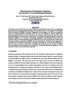
the error prone task of programmers to synchronize various parts of the code of components as shown in Figure 1 is no longer needed. Especially in a component-based programming model it is very important to avoid those kind of fine-grained code synchronization used in Figure 1 as it damages component encapsulation. Figure 7 illustrates an extended UML sequence diagram. This sequence diagram shows an observer component attached to an observable component. First the message deploy() is called. A new observer is created and attached to the observable. Then the state of the observable is changed. This results in calling notify(), which leads to sending asynchronous messages update() to all attached observers. Once the messages are processed, the observers request the new state from the observable component. Figure 7 illustrates a possible thread structure and concurrency situation. Each thread is shown by a grey box. The communication sequences shown within these boxes are performed by the corresponding thread. Thread 1 and Thread 2 could be the same thread. This depends on the caller. Either both have the same caller, then Thread 1 and Thread 2 are identical, or the callers are different, then Thread 1 and Thread 2 are not identical. Moreover Thread 3 and Thread 4 are newly created threads to process the received asynchronous messages update(). In addition, Figure 7 illustrates that the sequence is split up into several observation points applying our operational semantics. These observation points are the points in execution to synchronize all concurrently executed threads. As discussed in Section 4, an observation point exists for each method call or method return following our operational semantics. Consequently, for each thread entering as well as leaving the communication sequence an observation point exists. Moreover, as shown in Thread 2, threads may be divided into several observation points. Either as a method call is performed within the thread - in our case the method notify() is called - or another thread causes an observation point - in our case Thread 3 causes two additional observation points within the execution of Thread 2. 15
Rausch
Fig. 7. Interleaving threads and corresponding observation points given by the operational semantics.
8
Tool Support
In order to apply the presented concepts in practice, proper tool support is a key success factor. As already mentioned, we have developed a tool support for modeling, code generation and system execution - called DesignIt [17]. Software engineers can use DesignIt to model the component-based software system. To do this, the software engineer uses a CASE tool to develop a UML-based model of the desired component-based software systems. In doing so, the description techniques presented in the previous section should be used - component diagrams for the static structure and syntax, and activity diagrams to model the behavior of methods and messages. Currently, the CASE tool Together is supported directly. All modeling samples, the UML profile defining UML extensions, and the XML generator are implemented as plug-ins for Together. However, any other CASE tool may be used. For this, a corresponding XML generator has to be provided. 16
Rausch
Fig. 8. Development cycle using DesignIt.
As shown in Figure 8, a XML file is generated out of the UML model (step 1). This XML file is a simple textual representation of the UML model. We could have used XMI as textual representation. XMI has to support the complete bunch of UML elements. We only need the proposed extended component and activity diagrams for the DesignIt environment. To keep the following processing tasks simple, we have decided to define our own simple XML representation with respect to the proposed extended component and activity diagrams. XSLT transformations are used to generate the complete Java program code out of the XML files (step 2). The resulting Java components are then executed and debugged within the run-time system (step 3). When defects are detected in this step, the program can be debugged and analyzed. Once the problem is identified, it can be solved by changing the UML model (step 4). Afterwards, the whole cycle can be iteratively applied until the implementation is correct. To sum up, the DesignIt tool environment supports pure forward code generation. As the code is generated completely - no more coding is required - there is no need for backward code engineering. The execution and debugging environment of DesignIt is distributed itself. It is implemented using CORBA as distribution and network communication technique. The execution environment is a CORBA server. For each component type, a separate CORBA server is started. Even the debugger is started within an own CORBA server. Hence, the execution environment, the debugger, and each component type can be executed on a separate computer. Figure 9 shows a screenshot of the debugging environment of DesignIt. On the top level of the tree, each available server is shown. In the shown case, three additional distributed servers exist: one for the runtime environment, one for all instances of component type CB, and the other for all instances of 17
Rausch
Fig. 9. Debugging Environment of DesignIt.
component type CA. Moreover, for each component instance the current status and its syntactical interface are shown. Using this debugging environment, asynchronous messages or method calls from outside the system can be initiated. Once the messages resp. method calls are stored in the run-time environment, the whole distributed and concurrent system can be executed step by step. Each step represents an observation point in the sense of our operational semantics. Once an inconsistency appears, the debugging environment stops the system execution and informs the software engineer about the presence of a possible inconsistency situation as discussed in Section 6. The software engineer then can analyze the situation and fix the model until it is correct.
9
Conclusion
The ability to develop and maintain distributed concurrent component-based software systems is essential for modern software engineering. To bridge the gap between the vertical component-based decomposition of software systems and the horizontal concurrent execution flow in software systems, an operational semantic for distributed concurrent components has been elaborated. This model also includes hierarchical components - software systems that contain components which are again composed out of so-called sub-components. This has not been presented in the paper but it is included in the complete formal semantics in [15]. This model provides a sound and realistic semantic foundation for this kind of software systems: it is powerful enough to handle dynamically changing structures, shared global state, asynchronous message communication, and 18
Rausch
concurrent method execution. The overall system behavior can be calculated from the concurrently executed threads and their behavior relations. Based on the operational semantics inconsistent system states, especially caused by the concurrent execution, can be detected during run-time and further system execution can be stopped. Moreover, textual and graphical description techniques have been presented to describe this kind of concurrent component-based software systems. A complete and formally founded semantically mapping of the description techniques to the operational semantics has not been presented in the paper. This has already been elaborated in [15]. Based on this semantics complete code generation and execution within the run-time environment is supported. Tool support for modeling, code generation and system execution has been implemented and used in small case studies. However, further improvement has to be done. Moreover tool support for reasoning on the specifications could be addressed. Currently in [15] concepts for reasoning about the changes of component composition in case of component evolution are already elaborated and implemented. Further tool support concerning the consistency between specification and code may be a worth full improvement. Case studies and industrial experiences have to be undertaken to show whether the proposed approach is of practical relevance or not. The formal model could be extended to integrate the concept of exceptions. Moreover, additional description techniques like for instance sequence diagrams to model system traces and test cases could be integrated. The tool support may be extended to integrated run-time test and verification, failure analysis assistance, and code generation for additional target platforms.
10
Acknowledgements
My thanks to Christian Bartelt, Arnd Poetzsch-Heffter, Marcus Reitz, Marcus Seiler, Thomas Ternit for input and comments to this work.
References [1] Standish Group International, Inc. Collaborating on Project Success. Software Magazine, February/March 2001. Wiesner Publishing. 2001. [2] Object Management Group. OMG Unified Modeling Language Specification, Version 2.0. Technical Report, OMG. 2005. [3] Gary T. Leavens, Albert L. Baker, Clyde Ruby. Preliminary design of JML: A behavioral interface specification language for Java. Technical Report 98-06d, Iowa State University, Department of Computer Science. 1999. [4] Jos B. Warmer, Anneke G. Kleppe. The Object Constraint Language (Second Edition). Addison Wesley Publishing Company. 2004.
19
Rausch
[5] Stephen J. Mellor, Marc Balcer. Executable UML. Addison-Wesley Professional. 2002. [6] Luigi Lavazza, Gabriele Quaroni, Matteo Venturelli. Combining UML and formal notations for modeling real-time systems. Proceedings of the 8th European software engineering conference. 2001. [7] Marc Richters. A Precise Approach to Validating UML Models and OCL Constraints. Logos Verlag Berlin. 2001. [8] UML/EJB Mapping Specification. Java Community Process Document JSR26, 2001. [9] Charles A. Hoare. Communicating Sequential Processes. Prentice Hall. 1985. [10] Martin Abadi, Luca Cardelli. A Theory Of Objects. Springer Verlag. 1996. [11] Manfred Broy, Ketil Stlen. Specification and Development of Interactive Systems. Springer Verlag. 2001. [12] Handbook of Process Algebra. Jan A. Bergstra, Alban Ponse, and Scott A. Smolka, Editors. Elsevier, ISBN: 0-444-82830-3, 2001. [13] D. Harel, B. Rumpe. Meaningful Modeling: What’s the Semantics of “Semantics”?. In: IEEE Computer, Volume 37, No. 10, pp 64-72, IEEE, October 2004. [14] Klaus Bergner, Manfred Broy, Andreas Rausch, Marc Sihling, Alexander Vilbig. A Formal Model for Componentware. In Foundations of Component-Based Systems, Cambridge University Press. 2000. [15] Andreas Rausch. Componenteware: Methodik des evolution¨aren Architekturentwurfs. PhD Thesis, Technische Universit¨at M¨ unchen. Herbert Utz Verlag. 2001. [16] Erich Gamma, Richard Helm, Ralph Johnson, John Vlissides. Design Patterns, Elements of Reusable Object-Oriented Software. Addison Wesley Publishing Company. 1995. [17] DesignIt. Homepage of DesignIt. http://designit.informatik.tu-muenchen.de. 2005.
20