Feb 3, 2016 - {gpekhime,tcm}@cs.cmu.edu. {adwait,das ..... The remaining registers are not enough to schedule an entire extra thread block, which leaves a ...
A Framework for Accelerating Bottlenecks in GPU Execution with Assist Warps Nandita Vijaykumar Gennady Pekhimenko Adwait Jog† Saugata Ghose Abhishek Bhowmick Rachata Ausavarungnirun Chita Das† Mahmut Kandemir† Todd C. Mowry Onur Mutlu † Pennsylvania State University Carnegie Mellon University {nandita,ghose,abhowmick,rachata,onur}@cmu.edu {gpekhime,tcm}@cs.cmu.edu {adwait,das,kandemir}@cse.psu.edu
arXiv:1602.01348v1 [cs.AR] 3 Feb 2016
Abstract Modern Graphics Processing Units (GPUs) are well provisioned to support the concurrent execution of thousands of threads. Unfortunately, different bottlenecks during execution and heterogeneous application requirements create imbalances in utilization of resources in the cores. For example, when a GPU is bottlenecked by the available off-chip memory bandwidth, its computational resources are often overwhelmingly idle, waiting for data from memory to arrive. This work describes the Core-Assisted Bottleneck Acceleration (CABA) framework that employs idle on-chip resources to alleviate different bottlenecks in GPU execution. CABA provides flexible mechanisms to automatically generate “assist warps” that execute on GPU cores to perform specific tasks that can improve GPU performance and efficiency. CABA enables the use of idle computational units and pipelines to alleviate the memory bandwidth bottleneck, e.g., by using assist warps to perform data compression to transfer less data from memory. Conversely, the same framework can be employed to handle cases where the GPU is bottlenecked by the available computational units, in which case the memory pipelines are idle and can be used by CABA to speed up computation, e.g., by performing memoization using assist warps. We provide a comprehensive design and evaluation of CABA to perform effective and flexible data compression in the GPU memory hierarchy to alleviate the memory bandwidth bottleneck. Our extensive evaluations show that CABA, when used to implement data compression, provides an average performance improvement of 41.7% (as high as 2.6X) across a variety of memory-bandwidth-sensitive GPGPU applications. We believe that CABA is a flexible framework that enables the use of idle resources to improve application performance with different optimizations and perform other useful tasks. We discuss how CABA can be used, for example, for memoization, prefetching, handling interrupts, profiling, redundant multithreading, and speculative precomputation.
1. Introduction Modern Graphics Processing Units (GPUs) play an important role in delivering high performance and energy efficiency for many classes of applications and different computational platforms. GPUs employ fine-grained multi-threading to hide the high memory access latencies with thousands of concurrently running threads [58]. GPUs are well provisioned with different resources (e.g., SIMD-like computational units, large register files) to support the execution of a large number of
these hardware contexts. Ideally, if the demand for all types of resources is properly balanced, all these resources should be fully utilized by the application. Unfortunately, this balance is very difficult to achieve in practice. As a result, bottlenecks in program execution, e.g., limitations in memory or computational bandwidth, lead to long stalls and idle periods in the shader pipelines of modern GPUs [51, 52, 79, 103]. Alleviating these bottlenecks with optimizations implemented in dedicated hardware requires significant engineering cost and effort. Fortunately, the resulting under-utilization of on-chip computational and memory resources from these imbalances in application requirements, offers some new opportunities. For example, we can use these resources for efficient integration of hardware-generated threads that perform useful work to accelerate the execution of the primary threads. Similar helper threading ideas have been proposed in the context of general-purpose processors [22, 23, 27, 31, 32, 97, 122] to either extend the pipeline with more contexts or use spare hardware contexts to precompute useful information that aids main code execution (e.g., to aid branch prediction, prefetching, etc.). We believe that the general idea of helper threading can lead to even more powerful optimizations and new opportunities in the context of modern GPUs than in CPUs because (1) the abundance of on-chip resources in a GPU obviates the need for idle hardware contexts [27, 28] or the addition of more storage (registers, rename tables, etc.) and compute units [22, 75] required to handle more contexts and (2) the relative simplicity of the GPU pipeline avoids the complexities of handling register renaming, speculative execution, precise interrupts, etc. [23]. However, GPUs that execute and manage thousands of thread contexts at the same time pose new challenges for employing helper threading, which must be addressed carefully. First, the numerous regular program threads executing in parallel could require an equal or larger number of helper threads that need to be managed at low cost. Second, the compute and memory resources are dynamically partitioned between threads in GPUs, and resource allocation for helper threads should be cognizant of resource interference and overheads. Third, lock-step execution and complex scheduling—which are characteristic of GPU architectures—exacerbate the complexity of fine-grained management of helper threads. In this work, we describe a new, flexible framework for bottleneck acceleration in GPUs via helper threading (called Core-Assisted Bottleneck Acceleration or CABA), which exploits the aforementioned new opportunities while effectively
handling the new challenges. CABA performs acceleration by generating special warps—assist warps—that can execute code to speed up application execution and system tasks. To simplify the support of the numerous assist threads with CABA, we manage their execution at the granularity of a warp and use a centralized mechanism to track the progress of each assist warp throughout its execution. To reduce the overhead of providing and managing new contexts for each generated thread, as well as to simplify scheduling and data communication, an assist warp shares the same context as the regular warp it assists. Hence, the regular warps are overprovisioned with available registers to enable each of them to host its own assist warp. Use of CABA for compression. We illustrate an important use case for the CABA framework: alleviating the memory bandwidth bottleneck by enabling flexible data compression in the memory hierarchy. The basic idea is to have assist warps that (1) compress cache blocks before they are written to memory, and (2) decompress cache blocks before they are placed into the cache. CABA-based compression/decompression provides several benefits over a purely hardware-based implementation of data compression for memory. First, CABA primarily employs hardware that is already available on-chip but is otherwise underutilized. In contrast, hardware-only compression implementations require dedicated logic for specific algorithms. Each new algorithm (or a modification of an existing one) requires engineering effort and incurs hardware cost. Second, different applications tend to have distinct data patterns [87] that are more efficiently compressed with different compression algorithms. CABA offers versatility in algorithm choice as we find that many existing hardware-based compression algorithms (e.g., Base-Delta-Immediate (BDI) compression [87], Frequent Pattern Compression (FPC) [4], and C-Pack [25]) can be implemented using different assist warps with the CABA framework. Third, not all applications benefit from data compression. Some applications are constrained by other bottlenecks (e.g., oversubscription of computational resources), or may operate on data that is not easily compressible. As a result, the benefits of compression may not outweigh the cost in terms of additional latency and energy spent on compressing and decompressing data. In these cases, compression can be easily disabled by CABA, and the CABA framework can be used in other ways to alleviate the current bottleneck. Other uses of CABA. The generality of CABA enables its use in alleviating other bottlenecks with different optimizations. We discuss two examples: (1) using assist warps to perform memoization to eliminate redundant computations that have the same or similar inputs [13, 29, 106], by storing the results of frequently-performed computations in the main memory hierarchy (i.e., by converting the computational problem into a storage problem) and, (2) using the idle memory pipeline to perform opportunistic prefetching to better overlap computation with memory access. Assist warps offer a hardware/software interface to implement hybrid prefetching algorithms [35] with varying degrees of complexity. We also briefly discuss other uses of CABA for (1) redundant
multithreading, (2) speculative precomputation, (3) handling interrupts, and (4) profiling and instrumentation. Contributions. This work makes the following contributions: • It introduces the Core-Assisted Bottleneck Acceleration (CABA) Framework, which can mitigate different bottlenecks in modern GPUs by using underutilized system resources for assist warp execution. • It provides a detailed description of how our framework can be used to enable effective and flexible data compression in GPU memory hierarchies. • It comprehensively evaluates the use of CABA for data compression to alleviate the memory bandwidth bottleneck. Our evaluations across a wide variety applications from Mars [44], CUDA [83], Lonestar [20], and Rodinia [24] benchmark suites show that CABA-based compression on average (1) reduces memory bandwidth by 2.1X, (2) improves performance by 41.7%, and (3) reduces overall system energy by 22.2%. • It discusses at least six other use cases of CABA that can improve application performance and system management, showing that CABA is a primary general framework for taking advantage of underutilized resources in modern GPU engines.
2. Background A GPU consists of multiple simple cores, also called streaming multiprocessors (SMs) in NVIDIA terminology or compute units (CUs) in AMD terminology. Our example architecture (shown in Figure 1) consists of 15 cores each with a SIMT width of 32, and 6 memory controllers. Each core is associated with a private L1 data cache and read-only texture and constant caches along with a low latency, programmermanaged shared memory. The cores and memory controllers are connected via a crossbar and every memory controller is associated with a slice of the shared L2 cache. This architecture is similar to many modern GPU architectures, including NVIDIA Fermi [84] and AMD Radeon [10]. Core 1
Core 15
C C C
C C C
L1
L1
L1
L1
L1
L1
On Chip Network L2 DRAM
L2 DRAM
Figure 1: Baseline GPU architecture. from [115].
L2 DRAM Figure reproduced
A typical GPU application consists of many kernels. Each kernel is divided into groups of threads, called thread-blocks (or cooperative thread arrays (CTAs)). After a kernel is launched and its necessary data is copied to the GPU memory, the thread-block scheduler schedules available CTAs onto all the available cores [17]. Once the CTAs are launched onto the cores, the warps associated with the CTAs are scheduled onto the cores’ SIMT pipelines. Each core is capable of con-
2
currently executing many warps, where a warp is typically defined as a group of threads that are executed in lockstep. In modern GPUs, a warp can contain 32 threads [84], for example. The maximum number of warps that can be launched on a core depends on the available core resources (e.g., available shared memory, register file size etc.). For example, in a modern GPU as many as 64 warps (i.e., 2048 threads) can be present on a single GPU core. For more details on the internals of modern GPU architectures, we refer the reader to [53, 61].
guish applications based on their primary bottleneck as either Memory or Compute Bound. We observe that a majority of the applications in our workload pool (17 out of 27 studied) are Memory Bound, and bottlenecked by the off-chip memory bandwidth. Second, for the Memory Bound applications, we observe that the Memory and Data Dependence stalls constitute a significant fraction (61%) of the total issue cycles on our baseline GPU architecture (1xBW). This fraction goes down to 51% when the peak memory bandwidth is doubled (2xBW), and increases significantly when the peak bandwidth is halved (1/2xBW), indicating that limited off-chip memory bandwidth is a critical performance bottleneck for Memory Bound applications. Some applications, e.g., BFS, are limited by the interconnect bandwidth. In contrast, the Compute Bound applications are primarily bottlenecked by stalls in the ALU pipelines. An increase or decrease in the off-chip bandwidth has little effect on the performance of these applications. Unutilized On-chip Memory. The occupancy of any GPU Streaming Multiprocessor (SM), i.e., the number of threads running concurrently, is limited by a number of factors: (1) the available registers and shared memory, (2) the hard limit on the number of threads and thread blocks per core, (3) the number of thread blocks in the application kernel. The limiting resource from the above, leaves the other resources underutilized. This is because it is challenging, in practice, to achieve a perfect balance in utilization of all of the above factors for different workloads with varying characteristics. Very often, the factor determining the occupancy is the thread or thread block limit imposed by the architecture. In this case, there are many registers that are left unallocated to any thread block. Also, the number of available registers may not be a multiple of those required by each thread block. The remaining registers are not enough to schedule an entire extra thread block, which leaves a significant fraction of the register file and shared memory unallocated and unutilized by the thread blocks. Figure 3 shows the fraction of statically unallocated registers in a 128KB register file (per SM) with a 1536 thread, 8 thread block occupancy limit, for different applications. We observe that on average 24% of the register file remains unallocated. This phenomenon has previously been observed and analyzed in detail in [3, 39, 40, 41, 63]. We observe a similar trend with the usage of shared memory (not graphed). Our Goal. We aim to exploit the underutilization of compute resources, registers and on-chip shared memory as an opportunity to enable different optimizations to accelerate various bottlenecks in GPU program execution. To achieve this goal, we would like to enable efficient helper threading for GPUs to dynamically generate threads in hardware that use the available on-chip resources for various purposes. In the next section, we present the detailed design of our CABA framework that enables the generation and management of these threads.
3. Motivation We observe that different bottlenecks and imbalances during program execution leave resources unutilized within the GPU cores. We motivate our proposal, CABA, by examining these inefficiencies. CABA leverages these inefficiencies as an opportunity to perform useful work. Unutilized Compute Resources. A GPU core employs fine-grained multithreading [105, 112] of warps, i.e., groups of threads executing the same instruction, to hide long memory and ALU operation latencies. If the number of available warps is insufficient to cover these long latencies, the core stalls or becomes idle. To understand the key sources of inefficiency in GPU cores, we conduct an experiment where we show the breakdown of the applications’ execution time spent on either useful work (Active Cycles) or stalling due to one of four reasons: Compute, Memory, Data Dependence Stalls and Idle Cycles. We also vary the amount of available off-chip memory bandwidth: (i) half (1/2xBW), (ii) equal to (1xBW), and (iii) double (2xBW) the peak memory bandwidth of our baseline GPU architecture. Section 6 details our baseline architecture and methodology. Figure 2 shows the percentage of total issue cycles, divided into five components (as described above). The first two components—Memory and Compute Stalls—are attributed to the main memory and ALU-pipeline structural stalls. These stalls are because of backed-up pipelines due to oversubscribed resources that prevent warps from being issued to the respective pipelines. The third component (Data Dependence Stalls) is due to data dependence stalls. These stalls prevent warps from issuing new instruction(s) when the previous instruction(s) from the same warp are stalled on long-latency operations (usually memory load operations). In some applications (e.g., dmr), special-function-unit (SFU) ALU operations that may take tens of cycles to finish are also the source of data dependence stalls. The fourth component, Idle Cycles, refers to idle cycles when either all the available warps are issued to the pipelines and not ready to execute their next instruction or the instruction buffers are flushed due to a mispredicted branch. All these components are sources of inefficiency that cause the cores to be underutilized. The last component, Active Cycles, indicates the fraction of cycles during which at least one warp was successfully issued to the pipelines. We make two observations from Figure 2. First, Compute, Memory, and Data Dependence Stalls are the major sources of underutilization in many GPU applications. We distin-
3
Memory Stalls
Data Dependence Stalls
Idle Cycles
Active Cycles
80% 60% 40%
bp
hs
dmr
NQU SLA
pt
1/2x BW 1x BW 2x BW
lc
1/2x BW 1x BW 2x BW
1/2x BW 1x BW 2x BW
1/2x BW 1x BW 2x BW
1/2x BW 1x BW 2x BW
STO
1/2x BW 1x BW 2x BW
NN
1/2x BW 1x BW 2x BW
sssp Avg.
1/2x BW 1x BW 2x BW
sp
1/2x BW 1x BW 2x BW
mst
1/2x BW 1x BW 2x BW
bh
1/2x BW 1x BW 2x BW
bfs
1/2x BW 1x BW 2x BW
sc
1/2x BW 1x BW 2x BW
SS
1/2x BW 1x BW 2x BW
PVR
Memory Bound
1/2x BW 1x BW 2x BW
1/2x BW 1x BW 2x BW
PVC
1/2x BW 1x BW 2x BW
1/2x BW 1x BW 2x BW
MM
1/2x BW 1x BW 2x BW
1/2x BW 1x BW 2x BW
SCP
1/2x BW 1x BW 2x BW
1/2x BW 1x BW 2x BW
BFS CONS JPEG LPS MUM RAY
1/2x BW 1x BW 2x BW
1/2x BW 1x BW 2x BW
1/2x BW 1x BW 2x BW
1/2x BW 1x BW 2x BW
1/2x BW 1x BW 2x BW
0%
1/2x BW 1x BW 2x BW
20% 1/2x BW 1x BW 2x BW
Percentage of Cycles
Compute Stalls 100%
mc Avg.
Compute Bound
Unallocated Registers, %
Figure 2: Breakdown of total issue cycles for 27 representative CUDA applications. See Section 6 for methodology. Figure reproduced from [115]. 100%
about these threads at the granularity of a thread block. However, at any point in time, the hardware executes only a small subset of the thread block, i.e., a set of warps. Therefore, we need to define the abstraction levels for reasoning about and managing helper threads from the point of view of the programmer, the hardware as well as the compiler/runtime. In addition, each of the thousands of executing threads could simultaneously invoke an associated helper thread subroutine. To keep the management overhead low, we need an efficient mechanism to handle helper threads at this magnitude. Second, GPUs use fine-grained multithreading [105, 112] to time multiplex the fixed number of compute units among the hundreds of threads. Similarly, the on-chip memory resources (i.e., the register file and shared memory) are statically partitioned between the different threads at compile time. Helper threads require their own registers and compute cycles to execute. A straightforward approach would be to dedicate few registers and compute units just for helper thread execution, but this option is both expensive and wasteful. In fact, our primary motivation is to utilize existing idle resources for helper thread execution. In order to do this, we aim to enable sharing of the existing resources between primary threads and helper threads at low cost, while minimizing the interference to primary thread execution. In the remainder of this section, we describe the design of our low-overhead CABA framework.
90% 80% 70% 60% 50% 40% 30% 20% 10% 0%
Figure 3: Fraction of statically unallocated registers. Figure reproduced from [115].
4. The CABA Framework In order to understand the major design choices behind the CABA framework, we first present our major design goals and describe the key challenges in applying helper threading to GPUs. We then show the detailed design, hardware changes, and operation of CABA. Finally, we briefly describe potential applications of our proposed framework. Section goes into a detailed design of one application of the framework. 4.1. Goals and Challenges The purpose of CABA is to leverage underutilized GPU resources for useful computation. To this end, we need to efficiently execute subroutines that perform optimizations to accelerate bottlenecks in application execution. The key difference between CABA’s assisted execution and regular execution is that CABA must be low overhead and, therefore, helper threads need to be treated differently from regular threads. The low overhead goal imposes several key requirements in designing a framework to enable helper threading. First, we should be able to easily manage helper threads—to enable, trigger, and kill threads when required. Second, helper threads need to be flexible enough to adapt to the runtime behavior of the regular program. Third, a helper thread needs to be able to communicate with the original thread. Finally, we need a flexible interface to specify new subroutines, with the framework being generic enough to handle various optimizations. With the above goals in mind, enabling helper threading in GPU architectures introduces several new challenges. First, execution on GPUs involves context switching between hundreds of threads. These threads are handled at different granularities in hardware and software. The programmer reasons
4.2. Design of the CABA Framework We choose to implement CABA using a hardware/software co-design, as pure hardware or pure software approaches pose certain challenges that we describe below. There are two alternatives for a fully software-based approach to helper threads. The first alternative, treating each helper thread as independent kernel code, has high overhead, since we are now treating the helper threads as, essentially, regular threads. This would reduce the primary thread occupancy in each SM (there is a hard limit on the number of threads and blocks that an SM can support). It would also complicate the data communication between the primary and helper threads, since no simple interface exists for inter-kernel communication. The second alternative, embedding the helper thread code within the primary thread kernel itself, offers little flexibility in adapting to runtime requirements, since such helper
4
threads cannot be triggered or squashed independently of the primary thread. On the other hand, a pure hardware solution would make register allocation for the assist warps and the data communication between the helper threads and primary threads more difficult. Registers are allocated to each thread block by the compiler and are then mapped to the sections of the hardware register file at runtime. Mapping registers for helper threads and enabling data communication between those registers and the primary thread registers would be non-trivial. Furthermore, a fully hardware approach would make offering the programmer a flexible interface more challenging. Hardware support enables simpler fine-grained management of helper threads, aware of micro-architectural events and runtime program behavior. Compiler/runtime support enables simpler context management for helper threads and more flexible programmer interfaces. Thus, to get the best of both worlds, we propose a hardware/software cooperative approach, where the hardware manages the scheduling and execution of helper thread subroutines, while the compiler performs the allocation of shared resources (e.g., register file and shared memory) for the helper threads and the programmer or the microarchitect provides the helper threads themselves. 4.2.1. Hardware-based management of threads. To use the available on-chip resources the same way that thread blocks do during program execution, we dynamically insert sequences of instructions into the execution stream. We track and manage these instructions at the granularity of a warp, and refer to them as Assist Warps. An assist warp is a set of instructions issued into the core pipelines. Each instruction is executed in lock-step across all the SIMT lanes, just like any regular instruction, with an active mask to disable lanes as necessary. The assist warp does not own a separate context (e.g., registers, local memory), and instead shares both a context and a warp ID with the regular warp that invoked it. In other words, each assist warp is coupled with a parent warp. In this sense, it is different from a regular warp and does not reduce the number of threads that can be scheduled on a single SM. Data sharing between the two warps becomes simpler, since the assist warps share the register file with the parent warp. Ideally, an assist warp consumes resources and issue cycles that would otherwise be idle. We describe the structures required to support hardware-based management of assist warps in Section 4.3. 4.2.2. Register file/shared memory allocation. Each helper thread subroutine requires a different number of registers depending on the actions it performs. These registers have a short lifetime, with no values being preserved between different invocations of an assist warp. To limit the register requirements for assist warps, we impose the restriction that only one instance of each helper thread routine can be active for each thread. All instances of the same helper thread for each parent thread use the same registers, and the registers are allocated to the helper threads statically by the compiler. One of the factors that determines the runtime SM occupancy is the number of registers required by a thread block (i.e,
per-block register requirement). For each helper thread subroutine that is enabled, we add its register requirement to the per-block register requirement, to ensure the availability of registers for both the parent threads as well as every assist warp. The registers that remain unallocated after allocation among the parent thread blocks should suffice to support the assist warps. If not, register-heavy assist warps may limit the parent thread block occupancy in SMs or increase the number of register spills in the parent warps. Shared memory resources are partitioned in a similar manner and allocated to each assist warp as and if needed. 4.2.3. Programmer/developer interface. The assist warp subroutine can be written in two ways. First, it can be supplied and annotated by the programmer/developer using CUDA extensions with PTX instructions and then compiled with regular program code. Second, the assist warp subroutines can be written by the microarchitect in the internal GPU instruction format. These helper thread subroutines can then be enabled or disabled by the application programmer. This approach is similar to that proposed in prior work (e.g., [22]). It offers the advantage of potentially being highly optimized for energy and performance while having flexibility in implementing optimizations that are not trivial to map using existing GPU PTX instructions. The instructions for the helper thread subroutine are stored in an on-chip buffer (described in Section 4.3). Along with the helper thread subroutines, the programmer also provides: (1) the priority of the assist warps to enable the warp scheduler to make informed decisions, (2) the trigger conditions for each assist warp, and (3) the live-in and live-out variables for data communication with the parent warps. Assist warps can be scheduled with different priority levels in relation to parent warps by the warp scheduler. Some assist warps may perform a function that is required for correct execution of the program and are blocking. At this end of the spectrum, the high priority assist warps are treated by the scheduler as always taking higher precedence over the parent warp execution. Assist warps should be given a high priority only when they are required for correctness. Low priority assist warps, on the other hand, are scheduled for execution only when computational resources are available, i.e., during idle cycles. There is no guarantee that these assist warps will execute or complete. The programmer also provides the conditions or events that need to be satisfied for the deployment of the assist warp. This includes a specific point within the original program and/or a set of other microarchitectural events that could serve as a trigger for starting the execution of an assist warp. 4.3. Main Hardware Additions Figure 4 shows a high-level block diagram of the GPU pipeline [43]. To support assist warp execution, we add three new components: (1) an Assist Warp Store to hold the assist warp code, (2) an Assist Warp Controller to perform the deployment, tracking, and management of assist warps, and (3) an Assist Warp Buffer to stage instructions from triggered
5
assist warps for execution.
Warp Live in/out Active Priority SR.ID Inst.ID SR.End Mask Regs ID
SR 0
Inst 0 Inst. 1
SR 1
. . .
. . .
. . .
.
‘
. . . .
Fetch SIMT Stack
Scoreboard
Inst.ID
3
1 Trigger Assist Warp Pipeline Controller 7 Utilization 2
Warp ID + Priority + Active Mask
Active Mask
D e c o 4 Assist Warp Store 5 d e SR.ID + I-Cache
Assist Warp 6 Buffer
Write Back
Issue Active Mask
. .
. .
. .
. .
. .
. .
. .
. .
. .
. .
. .
Figure 5: Fetch Logic: Assist Warp Table (contained in the AWC) and the Assist Warp Store (AWS). Figure reproduced from [115].
ALU Instruction Buffer
. .
We do, however, provision a small additional partition with two entries within the IB, to hold non-blocking low priority assist warps that are scheduled only during idle cycles. This additional partition allows the scheduler to distinguish low priority assist warp instructions from the parent warp and high priority assist warp instructions, which are given precedence during scheduling, allowing them to make progress.
Mem
Scheduler
Figure 4: CABA framework flow within a typical GPU pipeline [43]. The shaded blocks are the components introduced for the framework. Figure reproduced from [115].
4.4. The Mechanism
Assist Warp Store (AWS). Different assist warp subroutines are possible based on the purpose of the optimization. These code sequences for different types of assist warps need to be stored on-chip. An on-chip storage structure called the Assist Warp Store (Í) is preloaded with these instructions before application execution. It is indexed using the subroutine index (SR.ID) along with the instruction ID (Inst.ID). Assist Warp Controller (AWC). The AWC (Ë) is responsible for the triggering, tracking, and management of assist warp execution. It stores a mapping between trigger events and a subroutine index in the AWS, as specified by the programmer. The AWC monitors for such events, and when they take place, triggers the fetch, decode and execution of instructions from the AWS for the respective assist warp. Deploying all the instructions within an assist warp, backto-back, at the trigger point may require increased fetch/decode bandwidth and buffer space after decoding [23]. To avoid this, at each cycle, only a few instructions from an assist warp, at most equal to the available decode/issue bandwidth, are decoded and staged for execution. Within the AWC, we simply track the next instruction that needs to be executed for each assist warp and this is stored in the Assist Warp Table (AWT), as depicted in Figure 5. The AWT also tracks additional metadata required for assist warp management, which is described in more detail in Section 4.4. Assist Warp Buffer (AWB). Fetched and decoded instructions (Ë) belonging to the assist warps that have been triggered need to be buffered until the assist warp can be selected for issue by the scheduler. These instructions are then staged in the Assist Warp Buffer (Ï) along with their warp IDs. The AWB is contained within the instruction buffer (IB), which holds decoded instructions for the parent warps. The AWB makes use of the existing IB structures. The IB is typically partitioned among different warps executing in the SM. Since each assist warp is associated with a parent warp, the assist warp instructions are directly inserted into the same partition within the IB as that of the parent warp. This simplifies warp scheduling, as the assist warp instructions can now be issued as if they were parent warp instructions with the same warp ID. In addition, using the existing partitions avoids the cost of separate dedicated instruction buffering for assist warps.
Trigger and Deployment. An assist warp is triggered (Ê) by the AWC (Ë) based on a specific set of architectural events and/or a triggering instruction (e.g., a load instruction). When an assist warp is triggered, its specific instance is placed into the Assist Warp Table (AWT) within the AWC (Figure 5). Every cycle, the AWC selects an assist warp to deploy in a round-robin fashion. The AWS is indexed (Ì) based on the subroutine ID (SR.ID)—which selects the instruction sequence to be executed by the assist warp, and the instruction ID (Inst.ID)—which is a pointer to the next instruction to be executed within the subroutine (Figure 5). The selected instruction is entered (Î) into the AWB (Ï) and, at this point, the instruction enters the active pool with other active warps for scheduling. The Inst.ID for the assist warp is updated in the AWT to point to the next instruction in the subroutine. When the end of the subroutine is reached, the entry within the AWT is freed. Execution. Assist warp instructions, when selected for issue by the scheduler, are executed in much the same way as any other instructions. The scoreboard tracks the dependencies between instructions within an assist warp in the same way as any warp, and instructions from different assist warps are interleaved in execution in order to hide latencies. We also provide an active mask (stored as a part of the AWT), which allows for statically disabling/enabling different lanes within a warp. This is useful to provide flexibility in lock-step instruction execution when we do not need all threads within a warp to execute a specific assist warp subroutine. Dynamic Feedback and Throttling. Assist warps, if not properly controlled, may stall application execution. This can happen due to several reasons. First, assist warps take up issue cycles, and only a limited number of instructions may be issued per clock cycle. Second, assist warps require structural resources: the ALU units and resources in the load-store pipelines (if the assist warps consist of computational and memory instructions, respectively). We may, hence, need to throttle assist warps to ensure that their performance benefits outweigh the overhead. This requires mechanisms to appropriately balance and manage the aggressiveness of assist warps at runtime. 6
The overheads associated with assist warps can be controlled in different ways. First, the programmer can statically specify the priority of the assist warp. Depending on the criticality of the assist warps in making forward progress, the assist warps can be issued either in idle cycles or with varying levels of priority in relation to the parent warps. For example, warps performing decompression are given a high priority whereas warps performing compression are given a low priority. Low priority assist warps are inserted into the dedicated partition in the IB, and are scheduled only during idle cycles. This priority is statically defined by the programmer. Second, the AWC can control the number of times the assist warps are deployed into the AWB. The AWC monitors the utilization of the functional units (Ð) and idleness of the cores to decide when to throttle assist warp deployment. Communication and Control. An assist warp may need to communicate data and status with its parent warp. For example, memory addresses from the parent warp need to be communicated to assist warps performing decompression or prefetching. The IDs of the registers containing the live-in data for each assist warp are saved in the AWT when an assist warp is triggered. Similarly, if an assist warp needs to report results to its parent warp (e.g., in the case of memoization), the register IDs are also stored in the AWT. When the assist warps execute, MOVE instructions are first executed to copy the live-in data from the parent warp registers to the assist warp registers. Live-out data is communicated to the parent warp in a similar fashion, at the end of assist warp execution. Assist warps may need to be killed when they are not required (e.g., if the data does not require decompression) or when they are no longer beneficial. In this case, the entries in the AWT and AWB are simply flushed for the assist warp.
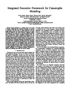
In bandwidth-constrained workloads, idle compute pipelines offer an opportunity to employ CABA to enable data compression in GPUs. We can use assist warps to (1) decompress data, before loading it into the caches and registers, and (2) compress data, before writing it back to memory. Since assist warps execute instructions, CABA offers some flexibility in the compression algorithms that can be employed. Compression algorithms that can be mapped to the general GPU execution model can be flexibly implemented with the CABA framework. 5.1. Mapping Compression Algorithms into Assist Warps In order to employ CABA to enable data compression, we need to map compression algorithms into instructions that can be executed within the GPU cores. For a compression algorithm to be amenable for implementation with CABA, it ideally needs to be (1) reasonably parallelizable and (2) simple (for low latency). Decompressing data involves reading the encoding associated with each cache line that defines how to decompress it, and then triggering the corresponding decompression subroutine in CABA. Compressing data, on the other hand, involves testing different encodings and saving data in the compressed format. We perform compression at the granularity of a cache line. The data needs to be decompressed before it is used by any program thread. In order to utilize the full SIMD width of the GPU pipeline, we would like to decompress/compress all the words in the cache line in parallel. With CABA, helper thread routines are managed at the warp granularity, enabling fine-grained triggering of assist warps to perform compression/decompression when required. However, the SIMT execution model in a GPU imposes some challenges: (1) threads within a warp operate in lock-step, and (2) threads operate as independent entities, i.e., they do not easily communicate with each other. In this section, we discuss the architectural changes and algorithm adaptations required to address these challenges and provide a detailed implementation and evaluation of Data Compression within the CABA framework using the BaseDelta-Immediate compression algorithm [87]. Section 5.1.3 discusses implementing other compression algorithms. 5.1.1. Algorithm Overview. Base-Delta-Immediate compression (BDI) is a simple compression algorithm that was originally proposed in the context of caches [87]. It is based on the observation that many cache lines contain data with low dynamic range. BDI exploits this observation to represent a cache line with low dynamic range using a common base (or multiple bases) and an array of deltas (where a delta is the difference of each value within the cache line and the common base). Since the deltas require fewer bytes than the values themselves, the combined size after compression can be much smaller. Figure 6 shows the compression of an example 64-byte cache line from the PageViewCount (PVC) application using BDI. As Figure 6 indicates, in this case, the cache line can be represented using two bases (an 8-byte base
4.5. Applications of the CABA Framework We envision multiple applications for the CABA framework, e.g., data compression [4, 25, 87, 118], memoization [13, 29, 106], data prefetching [15, 38, 54, 86, 108]. In Section 5, we provide a detailed case study of enabling data compression with the framework, discussing various tradeoffs. We believe CABA can be useful for many other optimizations, and we discuss some of them briefly in Section 8.
5. A Case for CABA: Data Compression Data compression is a technique that exploits the redundancy in the applications’ data to reduce capacity and bandwidth requirements for many modern systems by saving and transmitting data in a more compact form. Hardware-based data compression has been explored in the context of on-chip caches [4, 11, 25, 33, 49, 87, 89, 99, 118], interconnect [30], and main memory [2, 37, 88, 90, 91, 104, 114] as a means to save storage capacity as well as memory bandwidth. In modern GPUs, memory bandwidth is a key limiter to system performance in many workloads (Section 3). As such, data compression is a promising technique to help alleviate this bottleneck. Compressing data enables less data to be transferred from/to DRAM and the interconnect.
7
value, 0x8001D000, and an implicit zero value base) and an array of eight 1-byte differences from these bases. As a result, the entire cache line data can be represented using 17 bytes instead of 64 bytes (1-byte metadata, 8-byte base, and eight 1-byte deltas), saving 47 bytes of the originally used space.
whether all of the words at every SIMD lane were successfully compressed. In other words, if any one word cannot be compressed, that encoding cannot be used across the warp. We can perform this check by adding a global predicate register, which stores the logical AND of the per-lane predicate registers. We observe that applications with homogeneous data structures can typically use the same encoding for most of their cache lines [87]. We use this observation to reduce the number of encodings we test to just one in many cases. All necessary operations are done in parallel using the full width of the GPU SIMD pipeline. The high-level algorithm for compression is presented in Algorithm 2.
64‐byte Uncompressed Cache Line
8 bytes
8 bytes
0x00
0x80001d000
1 byte
8 bytes
1 byte
0x55
0x80001d000
0x00
Meta data
Base
0x10
0x00
0x10
0x80001d008
0x08
0x20
0x20
0x10
0x30
17‐byte Compressed Cache Line
0x80001d010
0x18
0x30
0x80001d018
Saved Space
47 bytes
Figure 6: Cache line from PVC compressed with BDI. Figure reproduced from [115].
Algorithm 2 BDI: Compression Our example implementation of the BDI compression algorithm [87] views a cache line as a set of fixed-size values i.e., 8 8-byte, 16 4-byte, or 32 2-byte values for a 64-byte cache line. For the size of the deltas, it considers three options: 1, 2 and 4 bytes. The key characteristic of BDI, which makes it a desirable compression algorithm to use with the CABA framework, is its fast parallel decompression that can be efficiently mapped into instructions that can be executed on GPU hardware. Decompression is simply a masked vector addition of the deltas to the appropriate bases [87]. 5.1.2. Mapping BDI to CABA. In order to implement BDI with the CABA framework, we need to map the BDI compression/decompression algorithms into GPU instruction subroutines (stored in the AWS and deployed as assist warps). Decompression. To decompress the data compressed with BDI, we need a simple addition of deltas to the appropriate bases. The CABA decompression subroutine first loads the words within the compressed cache line into assist warp registers, and then performs the base-delta additions in parallel, employing the wide ALU pipeline.1 The subroutine then writes back the uncompressed cache line to the cache. It skips the addition for the lanes with an implicit base of zero by updating the active lane mask based on the cache line encoding. We store a separate subroutine for each possible BDI encoding that loads the appropriate bytes in the cache line as the base and the deltas. The high-level algorithm for decompression is presented in Algorithm 1.
1: for each base_size do 2: load base, values 3: for each delta_size do 4: deltas = abs(values - base) 5: if size(deltas)