In this paper, we present and analyze a novel decoder ar- chitecture for LDPC convolutional codes (LDPCCCs). The proposed architecture enables high ...
A High-Throughput Programmable Decoder for LDPC Convolutional Codes Marcel Bimberg, Marcos B.S. Tavares, Emil Mat´uˇs and Gerhard P. Fettweis Vodafone Chair Mobile Communications Systems Technische Universitt Dresden, D-01069 Dresden, Germany Emails:{bimberg, tavares, matus, fettweis}@ifn.et.tu-dresden.de
Abstract In this paper, we present and analyze a novel decoder architecture for LDPC convolutional codes (LDPCCCs). The proposed architecture enables high throughput and can be programmed to decode different codes and blocklengths, which might be necessary to cope with the requirements of future communication systems. To achieve high throughput, the SIMD paradigm is applied on the regular graph structure typical to LDPCCCs. We also present the main components of the proposed architecture and analyze its programmability. Finally, synthesis results for a prototype ASIC show that the architecture is capable of achieving decoding throughputs of several hundreds MBits/s with attractive complexity and power consumption.
1. Introduction Low-density parity-check (LDPC) codes were discovered by Gallager in 1963 [6] and, nowadays, they are among the most promising error correcting schemes. The renewed interest in Gallager’s LDPC codes can be justified by their simplicity and by their attractive performance/complexity tradeoff. Currently, LDPC codes are being considered by the standardization committees of several future communication systems as serious candidates for the error control coding. The convolutional counterparts of Gallager’s LDPC codes – the LDPC convolutional codes (LDPCCCs) – were introduced in [1]. Compared with their block counterparts, the LDPCCCs are not limited to a unique blocklength. Instead, the same encoder/decoder structure can be used to encode/decode different codeword lengths, allowing easy adjustment for changing environment conditions. Therefore, they are highly recommended for next generations wireless communication systems, demanding high flexibility. The encoding of the LDPCCCs is performed in linear-time using shift-register operations and their decoding is facilitated by their highly structured underlying graphs.
As we will show in the next section, LDPCCCs can be decoded using low complexity iterative algorithms, where extrinsic information is exchanged between two decoding steps. In a hardware implementation, this exchange of messages is performed by interleavers [10]. When implementing a decoder for LDPC block codes, such interleavers become rapidly more and more complicated when issues as high throughput and huge block sizes are considered. Specifically, the implementation of more promising irregular block codes demands a combined code-architecture construction leading to a trade-off between hardware complexity and error correction performance. Moreover, parallelization concepts for decoding LDPC block codes are generally limited to the sub-block size of a base matrix they are derived from [7],[8]. The original construction of LDPCCCs presented in [1] is pseudo-random. In [11], Tanner et al. took advantage of the relation between convolutional codes and quasi-cyclic (QC) block codes to derive LDPCCCs. The obtained LDPCCCs through this method are time-invariant. When implementing time-invariant LDPCCCs, the problems with the exchange of messages can be easily overcome. For instance, the graph regularity guarantees low-complexity interleavers, very simple memory addressing and also homogeneity in the parallel architecture. The first architecture concepts for LDPCCC decoders were presented in [2] and [12], where an ASIC architecture was designed for encoding/decoding one special LDPCCC. The applied concepts were mainly derived from the pipeline decoding algorithm proposed in [1]. In this paper, we present a novel low-complexity highly parallel decoder architecture for time-invariant LDPCCCs. Although only the regular LDPCCCs from [11] are considered throughout this paper, our architecture is also capable of decoding irregular LDPCCCs. In this case, no changes in the hardware are necessary: irregular codes can be completely accommodated in our decoding architecture only by writing the corresponding software.
3. Hard decision:
2. LDPC Convolutional Codes
As described in [6], LDPC codes are defined by sparse parity-check matrices. In the case of LDPCCCs, the paritycheck matrices, which are called syndrome former matrices, show a diagonal structure and are semi-infinite [1]. Thus, the syndrome former HT of an LDPCCC can be written as ··· .. .
HTms ..
HT0 ..
. ···
HTms .. .
.
,
(1)
where the scalar submatrices HTν , ν = 0, 1, · · · , ms , have dimensions c × (c − b), and so determine the rate of the code, which is given by R = b/c (i.e., b represents the number of information bits and c the number of coded bits). As for LDPC block codes (LDPCBCs), a code sequence v belonging to an LDPCCC satisfies the parity check equation vHT = 0. Furthermore, if the number of ones in each row of HT is J and K is the number of ones in each column, the LDPCCC is called regular and is referenced as an (ms , J, K)-LDPCCC (otherwise it is called an irregular code). Obviously, J and K indicate the density of connections for the graph nodes. The parameter ms defines the memory of the convolutional code and consequently the critical distance of the graph. The critical distance of an LDPCCC is given by ms + 1 and represents the minimum temporal distance between nodes that are not connected to each other.
2.1. Decoding Algorithm
1
else
mij = ci = LLR(chi )
(2)
1. Check node update: �
mji = sign(mij )
i� ∈Vj
sign(mi� j ) · �min |mi� j | i ∈Vj\i
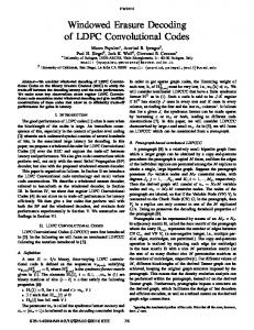
2.2. Parallel Decoding Concept LDPCCCs can be described by a bipartite graph as shown in Fig. 1 for a (3, 2, 3)-LDPCCC code. As the graph connections between variable and check nodes are the same at each time instant for time-invariant codes, these codes are well suited for a homogeneous, parallel VLSI implementation. The parallelization method applied within our implementation relies on the node level parallelization concept, which was investigated among others in [9]. Fig. 1(a) shows the principle underlying this parallelization concept, which is used as basis for developing our highly parallel decoding architecture. Here, variable nodes are grouped into nonpt = 2
� j � ∈Ci
�
mj � i −mji
Qi =Soft decision value
Processing window
D A
E
B
C
(a) Check-node
(b) Variable-node
Vector operand for CN operation Vector operand for VN operation Message vectors stored in memory
Figure 1. Principle of node level parallelization of order pt = 2
(3)
2. Variable node update: mij = ci +
(5)
The initialization phase is followed by the algorithm repeating through steps 1–3 until either the parity check equation vHT = 0 is fulfilled or a maximum number of iterations has been reached. In the implementation presented in section 3, the decoder executes a predefined number of decoding iterations.
Vector CN operation Vector VN operation
0. Initialization:
Qi ≥ 0
Symbols: chi channel information belonging to variable node i ci LLR of channel information belonging to variable node i mij message passed from variable node i to check node j mji message passed from check node j to variable node i Vj set of all variable nodes connecting to check node j Ci set of all check nodes connecting to variable node i vˆi estimated bit value for variable node i
Processing window
The Decoding of LDPCCCs can be accomplished by applying an iterative message passing algorithm to the received code sequence. As shown in [4], the Min-Sum algorithm is a good approximation for fixed point implementations. By utilizing log-likelihood-ratios (LLRs), this algorithm requires low complexity processing. The messages mij that are passed along the edges connecting variable and check nodes are calculated according to the following decoding equations:
if
g
HT =
HT0
0
Pro flo ces w sin
vˆi =
(4)
overlapping segments called processing windows of length pt . The message vectors of length pt are loaded sequentially and fed to the vector computing elements responsible for processing pt check or variable operations simultaneously. Efficient implementation of the vector processing can be achieved by using the SIMD computing model, which
OFFSET RAM
AGU0
AGU1
REG FILE
ReadAdr
FIFO AGU1
CMP
SHIFT RAM
Address generation (AG)
DMEM
WriteAdr ReadPort
ByteSel
WritePort
pt ⋅ N
FIFO CMP
BAR-SHIFT
pt ⋅ N
FIFO SHIFT FIFO -1 SHIFT
pt ⋅ N Proc. Proc. Node pt Node 1 Vector ALU
Vector FIFO
pt ⋅ N MUX
IMEM
DECODER
BAR-SHIFT
Control Unit
Datapath
pt ⋅ N
-1
pt ⋅ N
Figure 2. Block diagram of the LDPCCC decoder exploits the independence and regularity of the graph connections. Due to potential memory misalignments, the LDPCCC decoder demands the usage of a shuffle network. In Fig. 1(b), an example is given where the dashed rectangles represent the message vectors as they are stored in memory. According to this placement, the messages are already aligned for variable node operations, e.g., vector messages D and E. However, for check node operations, the memory alignment is not always provided, as one can see from vector messages B and C. In this case, a vector realignment procedure needs to be applied between variable and check node computation.
functional units are able to work in parallel, thereby avoiding stall cycles. Currently, the instruction words for our implementation have widths of 127 bits (without any compression). For prototyping purposes, we have chosen the size of the instruction memory to be 1024 × 127 bits. For specific implementations, IMEM can be downsized. As we will show in section 4, the total number of VLIWs required to implement a regular (ms , J, K)-LDPCCC is given by
3. Processor Architecture and Implementation Details
The data memory accommodates both the channel LLRs and the messages that are exchanged between variable and check nodes during the decoding iterations. An appropriate addressing scheme, that keeps the decoder flexible, will be described in more detail in section 3.2. As depicted in Fig. 1(b), each vector edge corresponds to one memory location that can be accessed by using a vector load/store instruction. In our implementation, pt = 64 values reside into one vector. This results in a total vector bit-width of 512 bits when N = 8 bits are used for soft-value representation. The vector edges are aligned according to the variable node perspective. The associated channel values are stored in the same manner. If we incorporate the additional 2�mS /pt �pt overhead slots surrounding one coded sequence of length L, the minimum memory size required for decoding can be summed up to: � � � � mS L +2 C= pt · K · (J + 1) · N [Bits], (7) K pt
Broadly speaking, our LDPCCC decoder is based on the synchronous transfer architecture (STA) presented in [5]. The STA provides an efficient platform for vectorized signal processing algorithms in terms of low power consumption and high performance. Therefore, it is a very good choice for the implementation of our parallelized LDPCCC decoder. The block diagram in Fig. 2 shows the disposition of the previously described decoding algorithm into an address generation and a datapath part. While address generation utilizes 16-bit fixed point arithmetic logic, the datapath is designed for vector processing, where each vector consists of pt 8-bit width data values.
3.1. Memory Organisation 3.1.1
Instruction Memory (IMEM)
In order to provide flexibility for decoding different LDPCCCs, specific program codes can be loaded into the instruction memory (IMEM). For this purpose, a DMA interface was implemented that is used to transfer data into the memories. By using very long instruction words (VLIWs), all
NV LIW = 4JK + 3J + 6K + 32. 3.1.2
(6)
Data Memory (DMEM)
where L/K is the number of time slots carrying coded bits. Typical maximum codeword lengths that can be decoded with a memory size of 64 KByte as in our implementation, range e.g. from 7594 bits for a (128, 5, 13)-LDPCCC up to 15104 bits for a (127, 3, 5)-LDPCCC. In order to keep the decoding pipeline filled, a two-port RAM was implemented
so that new values can be concurrently loaded into the processing nodes while computed results are written back into memory.
di
di SM ff 2'C
DEMUX