ple a desktop or laptop before deploying the agents to the. WSN devices. While numerous other methodologies exist for the fab- rication of MASs, such as [32] ...
A Methodology for the Deployment of Multi-Agent Systems on Wireless Sensor Networks Richard Tynan
Antonio Ruzzelli
G.M.P. O’Hare
Adaptive Information Cluster Smart Media Institute Department of Computer Science University College Dublin Belfield Dublin 4 Ireland Abstract Recent technological advances in wireless networking, IC fabrication and sensor technology have lead to the emergence of millimeter scale devices that collectively form a Wireless Sensor Network (WSN). The cost of production for a single node has been reduced to less than 1 dollar, paving the way for large scale deployments (millions of nodes per network) of such devices. It would seem that agent technology should be useful for these highly distributed networks in terms of intelligent network management and data harvesting for example. Indeed this has been shown to be the case, however multi-agent systems for WSNs are scarce. One reason for this is the difficulty in the deployment, testing and debugging of a distributed application for these devices due to the minimal (if any) user interfaces they possess. In this paper we will propose a methodology for the rapid development of a MAS for WSNs that allows for comprehensive testing and debugging, a luxury not available on current WSN devices. We also instantiate this methodology in a case study for evaluation purposes.
1. Introduction Though the concept of a sensor network is not new (DARPA initiated the Distributed Sensor Networks program in 1980), recent advances in microprocessor fabrication has lead to a dramatic reduction in the size and power consumed by such devices. Battery and sensing technology along with radio hardware have also followed a similar minaturisation trend. The aggregation of these advances has lead to the development of networked, millimeter-scale, sensing devices capable of complex processing tasks. Collectively
these form a Wireless Sensor Network (WSN), thus heralding new era for ubiquitous sensing technology. Large scale deployments of these networks have been used in many diverse fields such as wildlife habitat monitoring [19], traffic monitoring [4] and lighting control [26]. Some commercially available WSN platforms include Mica family [16], [7], Smart-Mesh [8], Ember [9], i-Beans [21], [24], Soapbox from VTT [29], Smart-Its [28], Cube sensor platform [30]. The minaturisation trend of their components has not only lead to their small, unobtrusive size but also their low power operation. Meaning that some of these devices can run for years off regular AA batteries [16], [7]. Other solutions don’t require batteries at all. They work by harvesting energy from tiny vibrations that occur naturally iBeans [21], [24] coupled with Energy Harvester [10]. The cost of production of a single node has been reduced to less than 1 dollar, paving the way for large scale deployments (millions of nodes per network) [16]. The inexpensive nature of such units is in stark contrast to older sensor devices [24]. It would seem that agent technology would be desirable for these highly distributed networks in terms of intelligent network management and data harvesting for example. Indeed this has been shown to be the case. Agents have been deployed previously on WSNs primarily to process the raw data in an intelligent fashion with a view to reducing transmissions - the single biggest factor in determining the longevity of the network [20], [22]. Other applications have used agents for the routing of packets around the network [1]. Agents have also been used in lighting control for intelligent energy conservation [26]. However, multi-agent systems for WSNs are scarce. One reason for this is the difficulty in the deployment, testing and debugging of a distributed application for these
devices due to the minimal (if any) visual interfaces they possess. This is because one of the major issues in WSNs is the longevity of the network. A display, no matter how minimal requires power to run thus reducing the life of the battery. Interfaces are also generally not needed since a WSN operates in a data acquisition role or in some cases as part of a control system [19]. A node considered to have one of the richest displays consists of 3 LEDS allowing for only 8 program execution states to be displayed [16]. Thus debugging applications for these devices can prove tedious and time consuming. Adapters for some of the devices do exist to allow probing of the devices memory but these can be quite expensive. The lack of debugging facilities is compounded when considering distributed, complex agent interactions. In order to address this issue some initial solutions involved the creation of middleware for the nodes of the network [12], [11], [18], which simplifies implementation for an individual node but does not aid in the debugging process as debugging must take place on the node as before. In this paper we will propose a methodology for the rapid development of a MAS for WSNs that allows for comprehensive testing and debugging, a luxury not available on current WSN device. It allows programmers to develop and comprehensively debug their applications using for example a desktop or laptop before deploying the agents to the WSN devices. While numerous other methodologies exist for the fabrication of MASs, such as [32] and [6], none of them to date have focussed on the inherent difficulty in deploying agents for devices that have such minimal interfaces as WSN nodes. Furthermore current sensor network methodologies such as [23] for creating power aware applications and [2] for increasing sensor accuracy, are typified by being highly application specific with a focus on imbuing an application with a specific trait such as power awareness. In the next section we present some background information on Wireless Sensor Networks, including their structure and operation. This leads us to our methodology, which is presented in section 3. We then present some of our methodological tool support in section 4 and finally we end with some of our conclusions in section 5.
2. Wireless Sensor Networks The main components of a WSN are a base-station and sensor nodes. The sensor nodes can relay their sensed data either directly to the base station or through each other depending on the scale of the network. In turn the base station can send commands down to the nodes to, for example, increase their sampling frequency. In some networks, when the base station is tethered to an adequate power supply, a greater transmission range can be achieved. This gives rise
to an asymmetry in the data acquisition and control protocols, where control commands are sent directly to the node but the data sent from the node to the base station is multi hopped. Of course multi hopping of the control commands from the base station can be used also. Multi hopping, while useful in extending the reach or scale of a WSN does have its pitfalls. The cost of transmitting a packet can be greatly increased depending on the distance a node is away from the base station. Second, since nodes nearest the base station, i.e. 1 hop away, will not only have to send their data but also that of all other nodes greater than a single hop, there will be a greater demand placed on the power supply of these nodes. It means that, in general, a nodes lifespan is inversely proportional to the number of hops it is away from the base station. To alleviate this problem, multiple base stations can be used, with the nodes only transmitting data to their local station. A second solution creates a hierarchy of nodes with varying power and transmission capabilities. Higher power nodes act as gateways to the base station for the lower powered sensors.
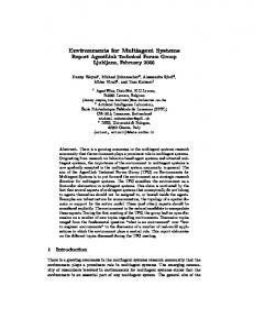
Figure 1. Two Berkeley Motes, the Mica2 (top left) and the Mica2Dot(bottom right)
There are also a number of other issues for practical applications using these devices. First is the issue of longevity. Networks of this type are usually battery powered and placed in regions that could prove hazardous for humans to revisit frequently for maintenance of the network. As such fault tolerance and power management have received considerable attention of late in the context of WSNs [14], [25]. Another area is that of the coverage of the network. How many nodes are required to adequately sense their environment [17]? In practice both monetary and spacial constraints prohibit a network deployment that is dense enough to meet all potential requirements of it. It will therefore be necessary, in some domains, to interpolate the values of the sensed medium at points between the sensor nodes [15], we will be returning to this important issue for our case study. A fundamental issue for practical WSNs is that of sen-
sor calibration [3]. When two nodes observe different values in their sensed data is that because they are seeing different events or because 1 (but perhaps both) of the sensors has malfunctioned. Of course calibration can be done prior to deployment, but if the malfunction causes its accuracy to degrade over time then a recalibration must occur on the fly after deployment. This is not a trivial problem, since the environment in which the motes are sensing usually cannot be controlled for the calibration to occur. In some WSNs the nodes of the network can perform considerable processing tasks and can be reprogrammed on a per-application basis. This facilitates the examination of raw sensed data in an intelligent fashion with transmissions perhaps only containing summarized information rather than the raw data. Processing capabilities vary from platform to platform. We have chosen the Mica2 Mote [16], [7] for our experimentation since they currently have the highest specification of commercially available platforms. It has 4KB of RAM, 128KB of instruction memory and 512KB of flash memory for logging purposes. They are equipped with a suite of sensory modalities, heat, light, sound, barometric pressure and humidity. We have also augmented this basic sensor array with with a chemical sensor, which can detect the presence of acid in the air and a textile pressure sensor to measure compression and contortion of a fabric.
Figure 2. A Sample WSN Configuration. The dashed line represents a wireless connection from each of the 3 motes to the base station and the solid line is a physical wire connecting the base station to a computer.
Figure 2 depicts a typical configuration for a WSN. 3 motes attached to a laptop or desktop through a base station. Networks comprised of such sensor platforms are charac-
terized by low computing capacity per individual platform, however the combined capacity of a large network may be substantial. The limit on individual sensor platform computing capacity is mainly due to the severe energy-usage constraints that current battery technologies impose [16]. Furthermore, because WSNs are often used in areas where a physical human presence is impractical or indeed undesirable, the systems are usually configured so that there is minimal usage of their computational and communication resources, limiting their abilities even more. Typically, the WSNs described in the literature may last years when power conservation methods are applied [16].
3. Why Intelligent Agents? Many applications of WSNs will require data acquisition, processing of this data and finally some form of action, with this cycle continuing endlessly for the life of the network. An initial solution to this could be to perform the processing or deliberation at the base-station of the WSN, which is where each node could periodically relay its sensed data. There are a number of reasons why this approach is unsuitable. First is the delay between the time the values are sensed and the time the base station receives then. In a multi-hop scenario a value may have to make many hops before reaching its destination. This delay will mean that any action the base-station chooses to take may be based on information that are not representative of the current state of the environment. Secondly the action commands issued from the base station to outlying nodes could potentially take an unacceptable amount of time to reach their target. In which case these commands may be undesired in the current situation and may be irreversible. The previous problem is therefore compounded in light of this and the overall delay between the detection of an event and the corresponding action could render this approach unusable. Consider a situation where some pollutant has been dumped in the environment and the nodes themselves have a chemical countermeasure to neutralize it. The lag between the detection and the decision to release the countermeasure could have allowed the pollution to spread to a far greater area. A third, related, problem is the power consumption of the multiple hops. There is a rule of thumb for many WSNs that the transmission of 1 bit is roughly equivalent to the execution of 1000 instructions [16]. It is evident therefore, that not only should transmission over a large number of hops be used sparingly but that when it does occur only summary data and not the raw data should be used in the transmission. On its own the intelligent processing of the raw data for the transmission of summary statistics would not require the use of agents. However, if the event identification and cor-
responding action is to be coordinated on a local level, in a neighborhood of the event for example, then distributed agents would be quite useful. In the previous pollution example a local negotiation process could ensue for the agents to best deploy their countermeasure once they detect that pollution has occurred. Certain factors like proximity to the center of the spill could influence the amount of countermeasure deployed. For this to happen the agents must first decide cooperatively where the center of the spill is located. This type of autonomic behavior is best coordinated on a local level and would address the third problem by only keeping transmission to a local level. In some cases no summary date need suffice, the base station could be informed of the detected event and the fact that it is currently being dealt with by the nodes. When we discuss intelligent agents in the context of WSNs we currently refer to the weak notion of agency [31]. It is unclear, however, whether it is in fact possible to accommodate an intentional BDI style agent on a device as computationally challenged as a WSN node.
4. Methodology Having detailed the utility in placing distributed, intelligent agents on WSNs we now turn our attention to the focus of this paper, a methodology for the deployment of such agents onto a WSN. The goal of this methodology is to take an application description and to implement it using agents to take advantage of the WSNs aggregated processing capabilities and to minimize transmissions through the intelligent local processing of the raw data. Our methodology consists of three phases which we will now describe in detail.
4.1. Centralized Base Station Implementation Given the application that we wish to implement using agents, the first phase involves the implementation of a centralized version on the base station. The base station is usually a device where debugging is a simple enough task, such as a laptop or desktop. The purpose of this phase is to identify and solve the idiosyncracies of the problem. Thinking in terms of agents we can view this as having a single agent on the base station. This configuration is depicted in figure 3. The sole base station agent receives the sensed data from the WSN. The WSN nodes in this instance are usually quite dumb in the sense that no intelligent processing takes place on them. According to some simple scheduling policy or in response to simple commands from the base station agent, the device simply polls its senses and then transmits this back to the base station. In most respects there is very lit-
Figure 3. Phase 1 of methodology: Single agent resides on base station to implement algorithm. Dashed lines represent wireless communication. Solid line represents wired communication between the base station and laptop.
tle to go wrong on the node allowing the focus of attention to be primarily on the correctness of the algorithm.
4.2. Distributed Base Station Implementation The second phase transforms this centralized solution into a distributed agent-based implementation again on the base station. Distributing an algorithm can prove difficult and so the maximum amount of debugging information is usually necessary at this point to ensure the correctness of the algorithm. Here we can make use of existing agent methodologies such as [32]. The key point to this phase, and to the entire methodology, is to have a mapping between the agents of the Multi-Agent System and the nodes in the final deployment. Numerous mappings exist, which are suitable for various different applications. We have identified 3 common mappings: One-to-One In this case one agent on the base station maps directly to one of the nodes of the network. So if there are ten devices in the embedded network the there should be ten agents in the MAS. We can now view each node as a perceptor of an agent on the base station. At the start of each agents deliberation cycle the agent will perceive its node and deliberate accordingly. Many-to-One For this mapping many agents map to an individual node. This is useful when, for example there may be one agent per sensory modality. Each agent will percieve its associated sense on a given node. One-to-Many One agent on the base station may map to a neighborhood of many nodes. The agent will perceive
the senses it is interested in, on the nodes in the neighborhood under its control. Inter-agent communication then conceptually corresponds to inter-neighborhood communication. For our applications we use AgentFactory [5], [6] in this phase, which conveniently, like most other agent frameworks, has an associated methodology for creating a MAS comprising its agents. Again in this phase the WSN nodes behave in the same simple manner as before, only now commands are received from its corresponding agent on the base station and its sensed value is reported to the same agent. We can see how this might be represented graphically in figure 4. The arrow lines here are important and the key to this process working. They represent the virtual link between the WSN node and its agent.
Figure 4. Phase 2 of methodology: MultiAgent System on Base station implements algorithm in a distributed manner. Dashed lines represent wireless communication. Solid line represents wired communication. Arrows represent virtual communication between WSN device and agent.
The future interaction of the agents on the nodes can now be modelled using the agents on the base station and debugged rigorously with ease. An important implication of this approach is that we are also able to model the physical communication of nodes over their radios. There is a practical limit to the transmission range of the WSN node so we can model the communication by only allowing an agent interact with another agent if it is possible for their corresponding devices to communicate over their radios. When multi hopping is not used or is only permitted for a subset of the network, this proves quite useful.
4.3. Distributed Agent Implementation For the final stage it is simply a matter of mapping the statements that govern the agents behavior, such as Commitment Rules [5], to the language of the target WSN device that will host the embedded agents. In our experience the first two phases are usually conducted on devices such as a laptop or desktop where debugging capabilities far exceed those on the embedded device. The result of this phase gives us a topology where the agents on the WSN distribute the load of executing an algorithm among themselves, which can allow for faster response time for complex algorithms and can reduce the number of transmissions in the network. The latter occurs because a packet that previously had to be multi-hopped to the base station could now be processed on a neighboring node or by the agent on the node itself. This can drastically increase the life span of a WSN as transmissions places the greatest drain on a WSN node’s battery [16].
Figure 5. Phase 3 of methodology: Verified agents are deployed to the WSN nodes.
Figure 5 depicts the final phase of the methodology. At this point the distribution of the algorithm is complete. One final important point to note is that the implementation languages used for the different phases need not be the same. To further clarify this methodology and to evaluate its effectiveness we will now walk through the steps of creating an agent based interpolation mechanism for a WSN. Details of this can be found in [27] and [15].
5. Methodological Tool Support In order to facilitate the usage of our methodology we have developed a number tools. We will detail three such tools: WSN data recorder/player, a sensor abstraction us-
ing the Observer design pattern and a wizard for the creation of a new program for the WSN node.
erty of the distributed approach requires testing and which was not a concern in the initial phase.
5.1. Logger and Player
5.2. Observable Network Abstraction
One of the big challenges in science is to create reproducible experiments for verification by third parties. In the context of WSNs this is notoriously difficult. An experiment is usually run once and the results obtained. A description of the experiment is usually the only medium used to convey the experiment performed. We aim to go one step further and to log the data for replay later to similar experiments for comparison purposes or the same experiment for verification. This fits in perfectly with the first and intermediate phases of the methodology. An experiment can be run and replayed many times, to a centralized solution and subsequently to the MAS on the base station, with different tweaks occurring in each to get a correct solution to the problem. With the transparent nature of the logger and player the initial solution and agents need never know their data is not live. In terms of the temporal aspect to some experiments, we log the time with each reading so we can maintain the delay experienced between readings from the live feed. Two important extensions follow on from this when timing is not critical:
We can further simplify the development process by providing an abstraction to the sensor network. Using the Observer design pattern [13] we can create an array of sensor objects. This array can be observed by the centralized solution so that when a new transmission is received, we can use a user defined mapping to map this message to the required sensor object. We can then inform all dependents of this array that its state has been changed and they can react accordingly. This in effect reduces the coupling between the application and and the physical network and means that the actual nodes could be replaced by a different type and the client code could remain the same. This tool facilitates the intermediate phase as the agents can perceive their corresponding sensor object or the user could define a forwarding agent to inform an agent that a new transmission has been received from the node. In each case transmissions can occur by invoking a method on the sensor object of the corresponding sensor that is to be transmitted to.
1. When the absolute value of the time between events need not be maintained a dramatic increase in the rate at which an experiment is performed can be achieved. In this instance the logger can maintain the relative time between triggering events i.e. say three consecutive events occur, the second occurring 1 second after the first and the third occurring 2 seconds after the second. This could be optimized to the 3 events only taking 3 (1 + 2) milliseconds to occur in the playback. We can then have a replayed experiment performed thousands of times in the duration it would have taken to run once in real time. 2. An even faster approach can be used when no temporal aspect is required. When this occurs events can be fired from the logger as fast as possible. This can lead to dramatic speed increases for performing experiments. This tool has important consequences for our development methodology. The first and intermediate phases could now in fact be separated into two subphases each. Initially they could be developed using live data (which is also logged). Once a critical mass of data is reached, the development could switched to the replayed data for testing. It may seem at first that if this critical mass is reached during the first phase that no more live experiments need occur, however this may not be the case if a particular prop-
5.3. New Project Wizard When beginning a new project in TinyOS there are a number of files that must be created. Conveniently, there is a pattern to the file names and content of each file, which allows automation of this process to some extent by having the user enter simple values, such as the project name. The IDE will then automatically generate a shell of the application. There are usually three files in the beginning of an application - a Makefile, a top level wiring configuration and a module that implements the functionality of the configuration. To begin, the IDE first asks the user to enter the project name, then the directory in which to create the project. This is all it requires to generate the applications code. First it creates a project directory with the project name, in the directory specified by the user for the project. It then generates the files of the application in this directory.
Figure 6. Code generated by the New Project Wizard for the Makefile file.
The first file created is the Makefile file. The template code for this is given in figure 6. We substitute the actual
project name in place of the placeholder then starting in the directory specified by the user the IDE checks the directory for a Makerules file. If not found it searches the parent of the current directory. It repeats this until it finds the file and each time it moves up a level in the file tree it concatenates an extra ../ onto the path for the Makerules file. It terminates when it has either found the required file or has reached the root of the file system.
Figure 7. Code generated by the New Project Wizard for the Top Level Configuration file.
The next file generated is given the name of the project and the extension .nc and is the top level configuration file for the application. It is responsible for wiring the components and modules of the application together. So a configuration or module that uses a particular interface must be wired to a component that provides the same interface if it is to be used in the application. Most applications require the use of the Main component and the StdControl interface to provide a point of entry for program execution. By convention the module for a particular configuration is placed in a file with the same name as the configuration but with a capital M after the name. It also has a .nc file extension. So in the template for the configuration file in figure 7 we see that Main.StdControl is wired into the StdControl of the applications module. The final file produced is the module and its name is inserted into the placeholder. Since this module implements the StdControl interface there must be implementations of the three commands defined in the interface. As previously stated this is defined in a file name M.nc by convention. This completes the code generation and the user can begin by writing their commands into the StdControl.start command. It must be noted that this general structure does not hold for all TinyOS projects, instead it is applicable in the majority of new applications. Another potential approach to facilitating the deployment of the agent based solution would be to equip the nodes in the network with the ability to receive a mobile agent. The individual agents could simply migrate to their respective nodes and the deployment would be complete.
Figure 8. Code generated by the New Project Wizard for the module file, which by convention is the implementation of a configuration.
6. Conclusions
Other approaches to deploying correct distributed algorithms on embedded devices exist, but they tend to be more formal and mathematical. This can place a great burden on an implementor to learn such methods. The key to our approach lies in the one-to-one mapping of agents to nodes and while not as rigorous, allows for the rapid deployment of a distributed algorithm with confidence that it has been debugged to a high standard. We have detailed our novel approach to the creation of a MAS for WSNs and shown that it can be used in the implementation of an important issue in Wireless Sensor Networks, namely spatial interpolation. Although the interpolation model used was simple and perhaps not the most accurate it served only to demonstrate the methodology in action and to validate its usefulness. Our methodology allowed for the verification of the correctness of the algorithm before deployment. Automation of this methodology is currently under investigation, in particular the final phase which could be solved by migrating the agents on the base station to their respective platforms.
7. Acknowledgements This material is based on works supported by the Science Foundation Ireland under Grant No. 03/IN.3/I361. The authors would also like to acknowledge the support of The Irish Research Council for Science, Engineering and Technology.
References [1] D. Braginsky and D. Estrin. Rumor routing algorithm for sensor networks. In WSNA, pages 22–31, September 2002. [2] S. M. Brennan, A. M. Mielke, D. C. Torney, and A. B. Maccabe. Radiation Detection with Distributed Sensor Networks. IEEE Computer, 37(8):57–59, 2004. [3] V. Bychkovskiy, S. Megerian, D. Estrin, and M. Potkonjak. A Collaborative Approach to In-Place Sensor Calibration. In 2nd International Workshop on Information Processing in Sensor Networks (IPSN’03), 2003. [4] S. Coleri, S. Y. Cheung, and P. Varaiya. Sensor Networks for Monitoring Traffic. In Allerton Conference on Communication, Control and Computing, 2004. [5] R. Collier. A Framework for the Engineering of AgentOriented Applications. PhD thesis, University College Dublin, 2001. [6] R. Collier, G. O’Hare, T. Lowen, and C. Rooney. Beyond Prototyping in the Factory of the Agents. In CEEMAS, 2003. [7] Crossbow Website. http://www.xbow.com. [8] Dust Inc. Website. http://www.dust-inc.com. [9] Ember Corporation Website. http://www.ember.com. [10] Ferro Solutions Website. http://www.ferrosi.com. [11] C.-L. Fok, G.-C. Roman, and C. Lu. Mobile agent middleware for sensor networks: An application case study. Technical Report WUCSE-04-73, Washington University, Washington University, Department of Computer Science and Engineering, St. Louis, 2004. [12] C.-L. Fok, G.-C. Roman, and C. Lu. Rapid development and flexible deployment of adaptive wireless sensor network applications. Technical Report WUCSE-04-59, Washington University, Washington University, Department of Computer Science and Engineering, St. Louis, 2004. [13] E. Gamma, R. Helm, R. Johnson, and J. Vlissides. Design Patterns: Elements of Reusable Object-Oriented Software. Professional Computing Series. Addison-Wesley Longman, Inc., 1995. [14] D. Ganesan, R. Govindan, S. Shenker, and D. Estrin. HighlyResilient, Energy-Efficient Multipath Routing in Wireless Sensor Networks. ACM SIGMOBILE Mobile Computing and Communications Review, 5(4):11–25, October 2001. [15] D. Ganesan, S. Ratnasamy, H. Wang, and D. Estrin. Coping with irregular spatio-temporal sampling in sensor networks. ACM SIGCOMM Computer Communication Review , 34(1):125–130, January 2004. [16] J. Hill. System Architecture for Wireless Sensor Networks. PhD thesis, UC Berkeley, 2003.
[17] C.-F. Huang and Y.-C. Tseng. The Coverage Problem in a Wireless Sensor Network. In WSNA ’03: Proceedings of the 2nd ACM international conference on Wireless sensor networks and applications, pages 115–121. ACM Press, 2003. [18] P. Levis and D. Culler. Mate : a virtual machine for tiny networked sensors. In Architectural Support for Programming Languages and Operating Systems (ASPLOS), 2002. [19] A. Mainwaring, J. Polastre, R. Szewczyk, D. Culler, and J. Anderson. Wireless Sensor Networks for Habitat Monitoring. In International Workshop on Wireless Sensor Networks and Applications, 2002. [20] D. Marsh, R. Tynan, D. O’Kane, and G. O’Hare. Autonomic wireless sensor networks. Engineering Applications of Artificial Intelligence, 2004. [21] Millenial Net Website. http://www.millennial.net. [22] H. Qi, X. Wang, S. S. Iyengar, and K. Chakrabarty. Multisensor Data Fusion in Distributed SensorNetworks Using Mobile Agents. In 4th International Conference Information Fusion, 2001. [23] V. Raghunathan, C. Schurgers, S. Park, and M. B. Srivastava. Energy aware wireless sensor networks. IEEE Signal Processing Magazine, 19(2):40–50, March 2002. [24] S. Rhee, D. Seetharam, S. Liu, and N. Wang. iBean Network: An Ultralow Power Wireless Sensor Network. In UbiComp 2003, the Fifth International Conference on Ubiquitous Computing, 2003. [25] A. Salhieh and L. Schwiebert. Power Aware Metrics for Wireless Sensor Networks. International Journal of Computers and Applications, 26(4), 2004. [26] J. Sandhu, A. Agogino, and A. Agogino. Wireless Sensor Networks for Commercial Lighting Control: Decision Making with Multi-agent Systems. In AAAI Workshop on Sensor Networks, 2004. [27] D. Shepard. A two-dimensional interpolation function for irregularly-spaced data. 23rd ACM National Conference, 1968. [28] SmartIts Website. http://www.smart-its.org. [29] Soapbox Website. http://www.vtt.fi/ele/research/tel/projects/soapbox.html. [30] UCC SugarCube Website. http://www.nmrc.ie/research/mai-group. [31] M. Wooldridge and N. Jennings. Intelligent agents: Theory and practic. Knowledge Engineering Review, 1995. [32] M. Wooldridge, N. Jennings, and D. Kinny. The gaia methodology for agent-oriented analysis and design. Autonomous Agents and Multi-Agent Systems, 2000.