A microfluidic biochip for complete blood cell counts ... - World Scientific
Recommend Documents
Dec 11, 2015 - patient must travel to either a hospital with a large laboratory or to a ... counts from a clinical laboratory (Carle Foundation Hospital, Urbana, IL).
a LIMMS CNRS/IIS, University of Tokyo, Tokyo, JAPAN b Institute of ... time monitoring of the composition and modulation of the cell medium by comparing the.
Dec 4, 2017 - diagnosed as having HIV infection, and group C consisted of 500 patients diagnosed as having AIDS ... cells (WBCs) and platelet counts, were analyzed using Sysmex XP 100, a compact, ..... manual CD4 kit for evaluating the CD4 cell count
Arthur J. Epstein,4 and L. James Lee1,5,a). 1Nanoscale Science ... 2BioLOC, LLC, 1381 Kinnear Road Suite 100, Columbus, Ohio 43212, USA. 3Nanomaterial ...
Jul 3, 2017 - 1 Department of Bioengineering, University of Illinois at Urbana-Champaign, 1270 Digital Computer Laboratory, 1304 W. Springfield Ave., ...
Ming-jie Yin, Bo-bo Huang, A. Ping Zhang, Hwa-Yaw Tam, and Xue-song Ye. Abstractâ A ... normal range. Therefore, it has become extremely important to.
excellent between all in-office instruments and the ADVIA 120, but results varied in accuracy (comparability). Hemavet 950 and Heska CBC-Diff re-.
Metamyelocytes. None. Myelocytes. None. Promyelocytes, blasts, other. None. ABC-morphology. Hemoglobin, g / L. 140- 180. (males),. 120- 160. (females).
Srinivasan et al. presented a fabricated digital microfluidic biochip for protein stamping, which .... since space (real estate) is available. Fig. 2: Schematic view of ...
Sep 6, 2016 - a,. *, Amartya Dutta b. , Riya Majumder b. , Arpan Chakraborty b ... Digital microfluidic based biochip manoeuvres on the theory of microfluidic .... algorithm3,9 a PCB (Printed Circuit Board) of three layers could be devised, ...
All types of blood cells are formed by differentiation from a small self- ... variability in the number of platelets (PLA), red (RBC) and white blood cells (WBC) from.
c Department of Electrical & Computer Engineering, Purdue University, West Lafayette, IN, United States .... that when a fern spore sits inside the pore, the maximum distance from the ..... S.T. Wereley received bachelors degrees in mechani-.
Dec 29, 2014 - lithography. A single layer of ..... Stagge F, et al. (2013) STED super-resolution microscopy ... pumps by multilayer soft lithography. Science 288: ...
Dec 23, 2016 - and Xuesong Ye 1,2,4,*. 1 ... cell patterning is free of topographic constraints, it usually needs complex chemical modifications, such as ...
It is well-known that non-polar mole- cules prefer to non-polar ..... D.; Ulkus, L.; Smith, M. R.; Kwak, E. L.; Digumarthy, S.; Muzi- kansky, A.; Ryan, P.; Balis, U. J.; ...
Jul 20, 2011 - 3 NUS Graduate School for Integrative Sciences and Engineering, National ... 6 Department of Mechanical Engineering, National University of .... disk-like platforms with manifolds and a spinning motor plate to ...... Sethu, P.; Moldawe
Jun 12, 2018 - eptifibatide are highly effective in inhibiting thrombus for- mation, albeit insufficient for high-shear processing of sensi- tized (i.e., stored) blood.
Conclusions: Some automated analyzers are able to recognize and count blasts according to their characteristic cell types. Therefore, complete blood counts ...
Apr 18, 2013 - Correlation between Peripheral White Blood Cell. Counts and Hyperglycemic Emergencies. Wei Xu1,2 ,â, Hai-feng Wu3,â, Shao-gang Ma2 ...
May 29, 2013 - doi:10.1016/j.jim.2004.08.008. Baum, M., Muller-Steinhardt, M., .... Edwards, A. J., Bacon, T. H., Elms, C. A.,. Verardi, R., Felder, M., and Knight,.
parameters with emphasis on clinical applications and analytic quality. The problems of some traditional parameters of the CBC count, such as platelet counts,.
B, Expression of CD63 (grey filled) was analyzed by flow cytometry on T-MV of the indicated five cell lines. The respective isotype controls are shown as black ...
Jan 31, 2012 - Keywords: Acute myocardial infarction, blood cells count, creatine kinase, inflammation, ..... Which white blood cell subtypes predict in- creased ...
Jul 20, 2011 - Microfluidics is the science of studying fluid flow behavior at the ... case of neonatal care. ... for downstream analysis and diagnosis. ...... D.W.; Simpson, J.L.; Jackson, L.G.; Elias, S.; Holzgreve, W.; Evans, M.I.; Dukes, K.A.;.
A microfluidic biochip for complete blood cell counts ... - World Scientific
Dec 11, 2015 - a CBC, which typically include white blood cell (WBC) counts with ... The complete blood count (CBC) is among the most ubiquitous diagnostic.
ARTICLE
TECHNOLOGY
A microfluidic biochip for complete blood cell counts at the point-of-care U. Hassan1,2,3, B. Reddy, Jr.2,3, G. Damhorst2,3, O. Sonoiki1,2, T. Ghonge2,3, C. Yang4 & R. Bashir2,3
Complete blood cell counts (CBCs) are one of the most commonly ordered and informative blood tests in hospitals. The results from a CBC, which typically include white blood cell (WBC) counts with differentials, red blood cell (RBC) counts, platelet counts and hemoglobin measurements, can have implications for the diagnosis and screening of hundreds of diseases and treatments. Bulky and expensive hematology analyzers are currently used as a gold standard for acquiring CBCs. For nearly all CBCs performed today, the patient must travel to either a hospital with a large laboratory or to a centralized lab testing facility. There is a tremendous need for an automated, portable point-of-care blood cell counter that could yield results in a matter of minutes from a drop of blood without any trained professionals to operate the instrument. We have developed microfluidic biochips capable of a partial CBC using only a drop of whole blood. Total leukocyte and their 3-part differential count are obtained from 10 μL of blood after on-chip lysing of the RBCs and counting of the leukocytes electrically using microfabricated platinum electrodes. For RBCs and platelets, 1 μL of whole blood is diluted with PBS on-chip and the cells are counted electrically. The total time for measurement is under 20 minutes. We demonstrate a high correlation of blood cell counts compared to results acquired with a commercial hematology analyzer. This technology could potentially have tremendous applications in hospitals at the bedside, private clinics, retail clinics and the developing world. Keywords: Cytometry; Microfluidic; Complete Blood Cell Counts; Point-of-Care; Coulter Counting.
INNOVATION An automated and portable point-of-care blood cell counter capable of providing results in a matter of minutes from a blood drop (finger prick) could have tremendous impact in revolutionizing personalized health care in both the developing and the developed world. In this work, we have developed microfluidic biochips to count white blood cells (WBCs), three-part differential subtypes, red blood cells (RBCs) and platelets, using just 11 μL of whole blood in 20 minutes. The technology is based on purely electrical cell counting and does not require any fluorescent labels or manual off-chip pre-sample processing. We found a high correlation when our biochips cell counts were compared with the hematology analyzer counts from a clinical laboratory (Carle Foundation Hospital, Urbana, IL). INTRODUCTION The complete blood count (CBC) is among the most ubiquitous diagnostic tests in primary and acute care. For example, in acute radiation syndrome (ARS), a CBC test with leukocyte differentials is required for the rapid management of the disease1. In radiation and chemotherapy, the CBC is routinely performed to observe the necessary cells production by bone marrow to ensure the health of the patient. Inflammation, leukemia, tissue injury, bone marrow failure and immunodeficiency can all be identified by irregular leukocytes counts and their differentials. Similarly, bone marrow fibrosis, lymphoma, aplastic anemia and lupus erythematosus
are associated with abnormal platelet count. Excessive bleeding, kidney bleeding, cancer and mechanical trauma can be accompanied by changes in the RBCs count1–3. Thus, a microfluidic disposable and economical CBC test could help in monitoring all of these disorders at higher frequency, potentially enabling the diagnosis of diseases much earlier. CBC tests include counting of total WBCs, a five-part differential (lymphocytes, monocytes, neutrophils, basophils, eosinophils), RBCs, platelets and their indices (mean cell volume) and hemoglobin concentration. Most commercially available cell counting systems are flow cytometers or hematology analyzers2–4. The ubiquitous CBC is performed using automated hematology analyzers while flow cytometers are used for any specific cell counting (e.g., CD4+ T cells or CD8+ T cells for AIDS diagnostics or HIV management)5. Hematology analyzers can be both optical and electrical. In commercial systems, the infused blood is first split into two channels. The RBCs are then lysed in the WBC counting channel. In optical analyzers, a laser illuminates the cells as they pass through the flow cell in a single-file manner. The scattered light is collected by two photo-detectors. The scattered light collected by the photo detector in line with the laser is called forward scatter, and the scattered light collected by the photo-detector perpendicular to the laser is called backscatter. Forward scattered light determines the size of the cells and backscatter gives information on the membrane properties. The forward and backscatter plots allow us to differentiate total WBCs and their sub-types. In electrical hematology
ARTICLE analyzers, the blood cell counting is based on the cell size and membrane properties, which are probed by using kHz to MHz range frequencies with sensing electrodes. A microfluidic device capable of enumerating the blood cells from a drop of blood could have tremendous applications ranging from clinical testing laboratories to point-of-care settings6–9. Microfluidic devices for cell counting have been reported using coulter counters and using AC signals10–13. Holmes et al. has shown the total leukocyte count and its differential using multi-frequency analysis7. Most of the above mentioned microfluidic counters were based on impedance cell counting technology14,15. Nguyen et al. have also characterized a biochip for CBC; however, the study lacks comprehensive differential counts, demonstrates only a small number of samples for statistical validation, and reports a small dynamic range of cell counts of blood samples16. Recently, Smith et al. have also shown an image-based device for complete blood cell counts with off-chip sample preparation17. However, the translation of their optical device to a portable system will have illumination non-uniformity and higher noise issues that they also mentioned in their article17. In our previous studies, we have also characterized in detail our microfluidic impedance sensors to count CD4 and CD8 T cells for HIV diagnostics using a differential capture technique18,19. We have also characterized the coincidence effects in our counter20 and performed a detailed mathematical characterization of the electrical cell counting process21. In this current study, we report a comprehensive characterization of blood cell counting including total leukocytes and their three-part differentials, RBCs and platelet count. We demonstrate the operation of the device for a wider dynamic range of cell counts, including blood samples collected from patients admitted to a non-coronary Intensive Care Unit (ICU) at the Carle Foundation Hospital, Urbana, IL. The immune system of the ICU patients is often highly compromised and we were able to demonstrate a leukocyte dynamic range from as low as 200 cells/μL up to around 15,000 cells/μL. We also collected blood samples from cancer patients undergoing chemotherapy (anemic patients) and using our chip, we were able to show that these patients have significantly lower RBC and platelets counts when compared to healthy donor samples. Our blood cell counter exhibits the potential to improve patient care in a wide spectrum of medical settings. METHODS AND MATERIALS Experimental approach A schematic illustrating the overall approach for a chip capable of WBC counts (three-part differential), RBC counts and platelet counts is shown in Fig. 1. We begin with a drop of blood typically around 50 μL in volume. From this, we meter out 11 μL of blood off-chip using an automated switching valve to input to the chips (Supplementary Fig. 1). Since electrical differentiation of the cells is primarily based on size differences, platelets and RBCs can be differentiated electrically, and the lymphocytes can be differentiated from other types of WBCs based on the observed pulse amplitude. Two separate 202
1550009.indd 202
chips were used to obtain the three-part WBC differential and the RBC/ platelet counts. For WBC counts, the infused blood is exposed to the lysing and quenching solutions to eliminate the RBCs from the solution. As shown in the top path in Fig. 1, the solution now contains a mix of WBCs, including neutrophils (60%), lymphocytes (30%), monocytes (7.5%), eosinophils (3%) and basophils ( 0. The resulting differential signal A–B photoresists. CD-26 developer is then used to develop the wafers. An will lose the maximum amplitude of the pulse that corresponds to the cell adhesion layer of 25-nm titanium is evaporated which is then followed size. Thus, for differentiating between different cell types, the electrode by 75 nm of platinum deposition20,21. Wafer is kept in Microchem PG spacing should be greater than or equal to the maximum cell diameter remover for 20 min at 70°C to remove the undesired metal. that needs to be differentiated. In order to effectively differentiate between lymphocytes, granulocytes Power analysis and monocytes, the electrode spacing should be at least 15 μm, as the Power analysis is used to determine the sample size required to get the diameter of the granulocytes/monocytes ranges from 12–15 μm. The desired statistical values. In order to get the correlation coefficient, ρ = pulses obtained as the leukocytes pass over the counting electrodes are 0.9 we selected an alpha level (two tailed) of 0.01 and power at 0.9. For shown in Fig. 2c. The amplitude of the pulse is proportional to the size ρ = 0.9, Zα = 2.58. However, Zb = 1.28 for the desired 0.9 power level. of the cell. Supplementary Fig. 3 shows the cell voltage pulse amplitude The following equation is used to calculate the required sample size, histogram obtained with the sensing region consisting of the 5 μm spacing which gives N = 13. and width of the electrodes. Electrode spacing is less than the size of the 2 cells, resulting in less accurate cell differentiation between lymphocytes Zα + Zb ) ( and granulocytes + monocytes. The cell voltage pulse amplitude histogram N= +3 2 (1) ⎛ 1+ ρ ⎞ ⎤ 1⎡ was obtained with a sensing region consisting of the 15 μm spacing and log e ⎜ ⎢ ⎥ ⎟ width of the electrodes (Fig. 2d). Electrode spacing is greater than the 4⎣ ⎝1− ρ ⎠ ⎦ size of the cells, resulting in more accurate cell differentiation. 0.39 0.58 0.77 0.96 1.15 1.33 1.52
Amplitude (Volts)
Reagents • Lysing buffer: 0.12% (v/v) formic acid and 0.05% (w/v) saponin in DI. • Quenching buffer: 21.1785% v/v 10 × PBS + 2.301 g of sodium carbonate in DI water.
RESULTS AND DISCUSSION Total WBC and three-part differential count Erythrocytes are lysed by infusing lysing buffer in the microfluidic biochip. After the erythrocyte lysis the cell debris tends to clump and make “debris ghosts” which result in clogging of electrical cell counting aperture of 15 μm × 15 μm. The debris clump also produces an appreciable change in impedance and would result in background baseline voltage noise. In our previous study, we found that greater quenching time of about 48 seconds results in providing the shear stress long enough to disassociate the erythrocyte debris clumps18. However, adding the 48-second step in the biochip would not only increase the size of the chip but also result in high fluidic resistance of the biochip. Saponin helps in dissociating the debris. The blood was lysed on-chip with a blood:lysing ratio of 1.75:12. The lysing time was optimized for 9 seconds. The lysing process was halted as the quenching buffer composed of sodium carbonate and PBS is mixed with the solution. The blood to quenching ratio was then adjusted to 1.75:10. The prepared solution was passed through
1000
40
Precision studies of WBC and differential counting Repeated experiments were performed from a single blood sample to measure the precision of our cell counting experiments. The precision
b
35
800
30
600
White Blood Cells
400
Lymphocytes Granulocytes & Monocytes
200
25 20 15
SNR (dB)
Number of cells
a
the microfabricated platinum electrodes of 15 μm width and 15 μm spacing. The input signal to the electrodes was 7 V and 303 kHz is multiplexed with 1.7 MHz. The data were acquired at the sampling frequency of 500 kHz. The amplitude histogram of all the leukocyte voltage pulses is shown in Fig. 3a. It shows the distinct separation of the lymphocytes and granulocytes + monocytes. Voltage thresholds for cell counting were selected manually considering the minima in between debris and lymphocytes and lymphocytes and granulocytes + monocytes. We compared the biochip counts with the control count using 10 blood samples collected from patients admitted to the ICU (shown in red) and 13 blood samples from non-ICU donors (shown in blue). The comparison of the biochip total WBC counts with control counts is presented in Fig. 3b. There is a good correlation between the two methods with R2 = 0.95 and with total WBC recovery of 68.35%. The comparison of biochip total lymphocyte count with the control count is shown in Fig. 3c. It also shows a good correlation between the two methods with R2 = 0.96 and with total lymphocyte recovery of 71.83%. The comparison of biochip total granulocyte + monocyte count with the control count is presented in Fig. 3d. It shows a good correlation between the two methods with R2 = 0.96 and with total granulocyte + monocyte recovery of 68.02%.
10 5 0
0
Biochip total WBC count / μL
the electrodes was obtained by using the Zurich Instruments differential preamplifier HF2CA. The output signal from the lock-in amplifier is sampled using the PCI-6351 DAQ card (National Instruments). A customized Matlab program is written to perform the data analysis.
12000
y = 0.68x R² = 0.95
10000 8000 6000 4000 2000 0 0
3000
6000
9000
12000
15000
3000
y = 0.72x R² = 0.96
2500 2000 1500 1000 500 0 0
500 1000 1500 2000 2500 3000 3500 4000
Control Lymphocyte count /μL
d
Biochip (Gran.+Mono) count /μL
c
Biochip Lymphocyte count /μL
Control total WBC count /μL 12000
y = 0.68x R² = 0.96
10000 8000 6000 4000 2000 0 0
3000
6000
9000
12000
15000
Control (Neut.+Mono+Eison) count /μL
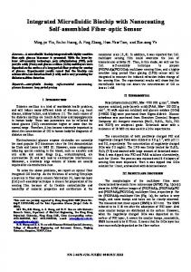
Figure 3 Comparison of biochip total leukocytes and their two-part differential (lymphocytes and granulocytes + monocytes) count from hematology analyzer control counts. Study is done on 23 blood samples with n = 10 collected from patients admitted to ICU (shown in red) and n = 13 from non-ICU donors (shown in blue). (a) Shows the histogram of the amplitude pulses for all the cells as they passed through the electrical counter. SNR of the leukocyte voltage pulses ranges from 25–37dB. (b) Comparison of biochip total WBC counts with the control count shows a good correlation with R2 = 0.95. (c) Comparison of biochip total lymphocytes count with the control count shows a good correlation with R2 = 0.96. (d) Comparison of biochip total granulocyte + monocyte count with the control count shows a good correlation with R2 = 0.96.
study for the total WBC, lymphocyte and granulocyte + monocyte counts from biochip in comparison with the control counts from the hematology analyzer is shown in Fig. 4. The different-colored bars represent the mean, and the error bars represent the standard deviation of the cell recoveries for samples A, B and C with 7, 8 and 9 repeated experiments, respectively.
Gran+Mono
80 70 60 50 40 30 20 10 0 Sample A (N=7)
Sample B (N=8)
Sample C (N=9)
Figure 4 Precision studies for WBC, lymphocyte and granulocyte + monocyte counts from biochip in comparison with the control counts. The different-colored bars represent the mean and the error bars represent the std. of the cell recoveries for samples A, B and C with 7, 8 and 9 repeated experiments, respectively.
Differentiating neutrophils from other granulocytes To differentiate between neutrophils vs. monocytes + eosinophils, we fitted the lognormal distribution to the high frequency (1.7 MHz) histogram of the granulocyte + monocyte population as shown in Supplementary Fig. 4. Non-ICU samples were selected for this study. The skewness of the fitted lognormal distribution to the high frequency granulocyte + monocyte histogram is linearly correlated with the control monocyte + eosinophil concentration with an R2 = 0.83 as shown in Fig. 5a. Equation (2) is used as a calibration to calculate the biochip monocyte + eosinophil concentration from the skewness of the fitted lognormal distribution to the high-frequency histogram of granulocyte + monocyte population. The comparison of the control monocyte + eosinophil count with the biochip’s calculated monocyte + eosinophil using Equation (2) as a fit factor, is shown in Fig. 5b. This provides a good correlation with an R2 = 0.80.
where Biochip Mono. + Eosino. count were obtained from Equation (2) and 0.68 value represents the recovery of the total granulocyte + monocyte population with low frequency. The comparison of the control neutrophil count with the calculated biochip neutrophil count is shown in Fig. 5c. The biochip neutrophil count is calculated using Equation (3). There is a good correlation with R2 = 0.82 and neutrophil recovery of 63.38%. The percentage of the total neutrophils comprising total granulocyte + monocyte should remain constant between control results and results calculated from biochip counts. The comparison of the neutrophil percent of the granulocyte + monocyte concentration from the control results with the calculated biochip neutrophil percentage is shown in Fig. 5d. There is a good correlation with R2 = 0.80. To further validate neutrophil counts obtained from the skewness analysis, we performed a control experiment in which lysed blood output was collected from the biochip. The sample was conjugated with CD66b fluorescent antibody (this antibody is specific to the neutrophils). After running it from flow cytometer, the neutrophil population was gated on the fluorescent vs. side scatter plot (Supplementary Fig. 5). The resulting neutrophil counts were compared with our electrical neutrophil counts obtained from skewness analysis. The analysis was done for three samples and the % error obtained was 5.2%, 3.7% and 6.1% respectively. Electrical counting of erythrocytes and platelets Optimization of electronic settings and digital signal filtering Platelets, being the smallest (~1–2 μm diameter) of all the blood cell types, are the most difficult to measure. To measure the platelets and the RBCs, the blood was diluted off-chip with PBS with a ratio of 1:300. The diluted blood was passed through the counting electrodes at 40 μL/min and the data was sampled at 1 Ms/sec. The sensing region of the counting electrodes was reduced to 5-μm spacing and width of electrodes with the
a
RBC
Vin = 1V
same channel aperture of 15 μm × 15 μm resulting in higher sensitivity. The amplitude histogram of the voltage pulses obtained is shown in Fig. 6. We varied the voltage and gain settings to acquire the platelets signal. The amplitude histogram of the voltage pulses was obtained as the cells in the diluted blood are passed through the counting region (Fig. 6a). The input voltage is set to 5 V with a differential amplifier gain of 10. The red arrow shows the zoomed-in version of the black dotted rectangle, which shows a smooth decrease of RBC distribution. The histogram with the input voltage of 10 V and a differential amplifier gain of 10 was obtained (Fig. 6b). The zoomed-in version shows an appearance of platelet distribution to the left of the RBC distribution. A typical voltage pulse corresponding to the RBC is shown in Fig. 7 with signal-to-noise ratio (SNR) of 21.7 dB. A typical voltage pulse corresponding to the platelet with an SNR of 11.4 dB is shown in Fig. 7. In order to obtain the maximum SNR for the pulses, the input voltage to the electrodes is varied from 1–10 V. Supplementary Fig. 6 shows the corresponding increase in the mean SNR of the RBC pulses with the increase in the input voltage. It shows a linear increase with an R2 value of 0.86. The frequency spectrum of the cell counting experiment data will allow us to observe the noise components in the frequency domain. Supplementary Fig. 7 shows the frequency spectrum of the entire cell counting data without performing any digital filtering. There is lowfrequency noise in the data because of the baseline drifts, electronic noise and power-line interference (60 Hz). Most of the cells pulses spectrum lies in the range of 5–90 kHz as shown in Supplementary Fig. 7a. There is an input frequency noise of 303 kHz and another high-frequency noise at 314.8 kHz as shown in Supplementary Fig. 7b. These can be removed by using a low-pass filter with cut-off-frequency less than 303 kHz. The low-frequency noise in the data is removed by applying a highpass filter with cut-off frequency of 20 Hz. To remove the power line frequency, a band-stop filter is used with cut-off frequencies of (58, 62) Hz. The second harmonic of the power line frequency is also removed using a band-stop filter with cut-off frequencies of (118, 122) Hz. The baseline drift is also corrected. The frequency spectrum of the cell counting experiment data after signal filtering is shown in Supplementary Fig. 8. RBC and platelet counting with off-chip dilution The erythrocyte (RBC) concentration in the blood sample is significant and thus requires dilution for accurate cell counting. The RBCs can be
b
RBC
Platelet
Vin = 10 V
Figure 6 The amplitude histograms of the voltage pulses obtained as the cells in the diluted blood (blood:PBS = 1:300) is passed through the counting channel. (a) The input voltage is 5 V with a differential amplifier gain of 10. The red arrow shows the zoomed-in version of the black dotted rectangle, which shows a smooth decrease of RBC distribution. (b) The input voltage is 10 V with a differential amplifier gain of 10. The zoomed-in version shows an appearance of platelet distribution to the left of the RBC distribution. 206
ARTICLE Blood is diluted with PBS with a ratio of 1:200 and flowed at 40 μL/ 0.25 RED BLOOD CELL PLATELET min through the electrical counter. 0.15 0.15 The precision results of RBC-counting are shown in Fig. 9a. ‘1’ shows the 0.05 0.05 healthy donor sample with a CV = 2.6% for five repeated experiments; -0.05 0 -0.05 0 100 200 300 400 100 200 300 400 ‘2’ shows a cancer donor sample -0.15 -0.15 with a CV = 5.5% for five repeated experiments; and ‘3’ shows anTime (μs) -0.25 Time (μs) -0.25 other cancer donor sample with a CV = 5.8% for four repeated experiments. The precision results of Figure 7 (a) A typical voltage pulse of an RBC with a signal-to-noise ratio (SNR) of 21.7 dB. (b) A typical voltage RBC-counting are shown in Fig. 9b. pulse of a platelet with an SNR of 11.4 dB. ‘1’ shows the healthy donor sample with a CV = 10.2% for five repeated experiments; ‘2’ shows a cancer differentiated from platelets and WBCs from the electrical voltage pulse’s donor sample with a CV = 8.1% for five repeated experiments; and ‘3’ amplitude histogram as the RBC is bigger than a platelet but smaller shows another cancer donor sample with a CV = 9.3% for four repeated than a WBC. The blood samples were diluted off-chip with different experiments. blood:PBS dilution ratios. We flowed the diluted blood sample through our impedance cell counter and count all the pulses; the sample contains RBC and platelet counting with on-chip dilution RBCs, platelets and all WBCs. The leukocytes comprise about 0.5% and The on-chip dilution is performed on the biochip; the schematic is platelets about 3–5% of the erythrocytes, and after dilution the leukocyte shown in Fig. 10. The PBS and the blood are infused in the biochip at concentration in the sample becomes very low — around 50 cells/μL, the indicated inlet ports. The PBS is mixed with blood at the ratio of resulting a negligible effect on the counting results. The control RBC 40:0.5 μL/min in the serpentine channels. The electrical counter counted counts were compared with the counts obtained from the biochip using the cells in the diluted blood as they pass through the electrodes. In 22 blood samples (Fig. 8a). Blood is diluted with PBS at different dilutions order to improve the SNR the width and spacing of the electrodes was (PBS:blood) and flowed through the biochip. It shows a good correlation reduced to 5 μm. between the two methods with R2 = 0.96 and the cell recovery of 96.35%. The Blood is diluted on-chip with PBS with flow rate ratio (blood: The cases for which the biochip noise is higher; platelet distribution did PBS = 0.5:40 μL/min). The resulting diluted blood is flowed through not appear. The noise comparison of the biochips for platelet counting is the electrical counter. The control RBC counts are compared with the given in ‘Discussion’ section. The control platelet counts were compared counts obtained from the biochip using 21 blood samples (Fig. 11a). with the counts obtained from the biochip using 13 blood samples It shows a good correlation between the two methods with R2 = 0.82 (Fig. 8b). It shows a good correlation in between the two methods with and the cell recovery of 93.52% after coincidence correction. The R2 = 0.84 and the cell recovery of only 51%. The decrease in the cell decrease in the cell recovery can be associated with the high number recovery can be associated with the high noise in the biochip, resulting in of coincidences at the low dilution factor. The control platelet counts loss of platelet pulses in the noise. Platelets, being the smallest (~1–2 μm are compared with the counts obtained from the biochip using 13 diameter), result in small impedance change. blood samples (Fig. 11b). It shows a good correlation between the two methods with R 2 = 0.90 and the cell recovery of 67.85%. The Precision studies of RBC and platelet counting decrease in the cell recovery can be associated with the high number Repeated experiments were performed from a single blood sample to of coincidences at the low dilution factor and loss of the platelets measure the precision of our RBC- and platelet-counting experiments. pulses in the noise. 0.25
be a limitation when it comes to achieving consistent properties and geometries of the elec250000 4000000 trodes. For example, the vari200000 ability in the selected threshold 3000000 value for total WBC counting 150000 was approximately 30% (Sup2000000 100000 plementary Information). In 1000000 point-of-care automated cell 50000 counters, the threshold selec0 0 tion can be automated since 1 2 3 1 2 3 the cartridges/electrodes will be commercially manufactured and the fabrication process is Figure 9 (a) Precision studies of RBC counting. ‘1’ shows the healthy donor sample with a CV = 2.6% for five repeated expected to be more consistent experiments; ‘2’ shows a cancer donor sample with a CV = 5.5% for five repeated experiments; and ‘3’ shows the and streamlined. cancer donor sample with a CV = 5.8% for four repeated experiments. (b) Precision studies of platelet counting. ‘1’ Microfluidic biochips utishows the healthy donor sample with a CV = 10.2% for five repeated experiments; ‘2’ shows a cancer donor sample lize an aggressive lysing step to with a CV = 8.1% for five repeated experiments; and ‘3’ shows the cancer donor sample with a CV = 9.3% for four repeated experiments. ensure the lysing of the RBCs as the desired time to perform this lysing should be small. Hematology analyzers use lysing reagents that result in lysing/quenching time in the order of 10 minutes. In point-of-care microfluidic biochips, using these regents with significant higher times will result in unacceptably large assay time and use of extra reagent volumes. This will also result in a much higher footprint of the device, thus directly affecting the cost per assay. However, with our rapid lysing solution to effectively lyse all erythrocytes and to ensure the complete dissociation of RBC debris clumps (to prevent clogging of the chips; one of major problem in point-of-care biochips), the lysing solution resulted in loss of leukocytes as well. In experiments for which we were able to see the platelet distribution; the standard deviation of the noise was less than 0.03 V. The baseline drift in the signal also got completely removed after the filtering and baseline correction algorithm as shown in Supplementary Fig. 9. However, for the experiments for which we were not able to see the platelet distribution, the standard deviation of the noise in the biochip is greater than 0.05 V. Also the baseline drift was very large compared to the good chips as shown in Supplementary Fig. 10. The signal averaging technique can be used to improve the SNR that only works if the noise is Gaussian white noise and not pink or brown noise having spectral characteristics of 1/f and 1/f2, respectively. We have shown the decrease in the standard deviation of chip noise with signal averaging. PBS is flowed through the electrical counter at 40 μL/min and the chip noise is recorded. The measured standard deviation of the chip noise was 0.0873 V. Supplementary Fig. 11 shows the decrease in Figure 10 Schematic of the RBC- and platelet-counting biochip. PBS is the standard deviation of the chip noise with signal averaging. Increased mixed with blood at the ratio of 40:0.5 in the serpentine channels. The number of samples for averaging will result in decreased standard deviaelectrical counter counted the cells in the diluted blood as they passed tion for the chip noise. After averaging with two samples, the standard through the electrodes. deviation is reduced to about 0.06 V, which further decreased to 0.04 V after signal averaging with three samples. Platelets are 1–2 μm in size as compared to the channel cross-section of 15 μm × 15 μm. Any platelets DISCUSSION flowing at the top of the channel might get lost in noise. This can be Our sensor has the potential to be translated to a commercial pointremedied by using hydrodynamic focusing23. For this we need to redesign of-care CBC biochip. However, being in early stages of development, the channel accordingly or introduce another buffer, which will not be there is much room to further improve the parameters including cell desirable for a point-of-care device, where one objective is to minimize recovery, voltage thresholds for cell counting, electrodes configuration the number of reagents. and skewness analysis for more sensitive and accurate results. Currently, After performing the high-pass filtering at 20 Hz and power-line threshold selection for the cell counting is performed manually while filtering at 60 and 120 Hz, the frequency spectrum of the RBC, platelet considering the minima between different populations. However, in a counting experimental data with the sampling rate of 1 MHz and input portable and completely automated CBC counter, this can be done using signal frequency of 303 kHz are obtained and shown in Fig. 6. The an automated algorithm considering two parameters, i.e., minima in red arrow shows voltage pulse frequency spectrum. The green arrow between two distributions and a preselected threshold value which will be shows a peak at 303 kHz, which can be further removed to decrease much more precise in mass manufactured cartridges and electrodes. The the chip’s noise. A low-pass filter of 200 kHz can be used to remove this variability in the biochip fabrication in the current research settings can noise. The standard deviation of the chip noise without using this filter 5000000
ARTICLE of fabrication and a controlled environb x 106 a 3.0 6 ment in a point-ofy = 0.68x y = 0.94x care counter. R² = 0.90 2.5 5 R² = 0.82 The applied 2.0 4 voltage used in the erythrocyte count1.5 3 ing experiments is 1.0 2 up to 10 V. The electrolysis of the cells 0.5 1 depends on many 0 0.0 x 105 x 106 factors including 0 1 2 3 4 5 6 0.0 0.5 1.0 1.5 2.0 2.5 3.0 3.5 applied voltage and Control Red blood cell count /μL Control Platelet count /μL whether it is DC or AC, the frequency of the applied voltFigure 11 Erythrocyte- and platelet-counting experiments with on-chip blood dilution. Blood is diluted on-chip with PBS with age, flow rate of the flow rate ratio (blood: PBS = 0.5:40 μL/min) and flowed through the biochip. (a) Comparison of the control RBC counts with 2 cells and the critical the counts obtained from the biochip using 21 blood samples with R = 0.82 and the cell recovery of 93.52%. (b) Comparison time for irreversible of the control platelet counts with the counts obtained from the biochip using 13 blood samples with R2 = 0.90 and the cell recovery of 67.85%. electroporation25–27. If the actual transmembrane voltage increases well above was 0.0564 V, which decreased to 0.0305 V after low-pass filtering was 1 V, then electroporation can begin to happen25. In our experimental performed on the data with cut-off frequency of 200 kHz. conditions, with 10-V peak voltage at frequency of 303 kHz, and using Holmes et al. were able to isolate the granulocytes from monocytes with intracellular resistivity reported in literature, the resulting transmembrane top-bottom electronic configuration that is more sensitive than our co-planar potential can be calculated to be around 2 V. So looking at transmembrane electrodes configuration7. However, top-bottom electrodes configuration potential only, we would be above the critical voltage to cause cell lysing. may impose some developmental challenges like alignment of electrodes However, the electroporation (and irreversible electroporation and cell within a few microns and electronic connectors arrangements from both lysing) is also critically dependent on the time that the cells are exposed layers, resulting in more complicated and potentially expensive cartridges. to the electrical field. The reported critical time for electrical lysis of The blood samples collected from the ICU patients sometimes have erythrocytes can vary anywhere between 100 μs to a few milliseconds25. abnormally high number immature granulocytes ranging from 10–2,200 In our case, with the flow rates used in our experiments, the pulse width cells/μL as compared to 10–20 cells/μL in healthy samples. The high across two electrodes is approximately 50 μs. During this 50 μs, the cell number of immature granulocytes will result in changing the skewness is exposed to different electric field strengths at different times during level of the fitted lognormal distribution. Thus, the regular correlation of the flow path over the electrodes. However, electroporation might have skewness with the control monocyte + eosinophil count does not hold happened to the erythrocytes resulting in damaging the cell membranes. with high number of immature granulocytes. When we fitted bimodal Hence, it is certainly likely that the SNR increase is not only due to distributions to the impedance histograms at high frequency (using increased voltage itself, but also due to electroporation or partial cell lysis maximum likelihood optimization for parameter estimation in Matlab), resulting from the increased electric field. It however does not cause an the fitting function was unable to converge or produced erroneous fitting error in the cell counting, which is the primary goal of our paper. values for cases where the monocytes population was less than