A Modular Control Architecture for a Small Electric Vehicle F. Santos1, J. Trovão1, A. Marques1, P. Pedreiras2, J. Ferreira3, L. Almeida2, M. Santos4 1 LSE-IEETA/DETI2 DEE-ISEC Instituto Politécnico de Coimbra Universidade de Aveiro 3030-199 Coimbra 3810-193 Aveiro Portugal Portugal {fred, jtrovao, lmarques}@isec.pt {pedreiras,lda}@det.ua.pt
Abstract This paper presents a fault-tolerant modular control architecture for an electrical vehicle (VEIL) equipped with x-by-wire sub-systems. The proposed architecture is based on COTS components and includes steer-bywire, brake-by-wire and accelerate-by-wire safety critical functions. The communication infrastructure is based on the FTT-CAN protocol, which provides the joint scheduling of message and tasks, according to a holistic approach.
1. Introduction Small electrical vehicles contribute to reduce air pollution and increase the mobility in urban areas, are more energy efficient and economic to operate and, at least in some aspects, present a better performance when compared with conventional internal combustion-based vehicles. VEIL (license free electrical vehicle) is a project undertaken by ISEC (Instituto Superior de Engenharia de Coimbra) and aims at designing a license free electrical vehicle [1], integrating automatic control functionalities, namely break, steer and accelerate-bywire systems. The adoption of x-by-wire technologies brings sizeable benefits to the automotive systems, permitting important weight and cabling reduction, increased flexibility and maintainability and has the potential to permit a more efficient energy usage, with a noticeable impact on the operational costs and pollution reduction. With the introduction of x-by-wire systems, mechanical sub-systems are being replaced by electronic systems incorporating sensors, ECUs (Electronic Control Unit) and actuators, interconnected by dependable realtime networks. Due to safety reasons, the former x-bywire systems were coupled with mechanical backups, which assured the subsystem operation in case of failures of the electronic subsystem. However, the gap of performance between the mechanical and the electronic systems has increased drastically, leading to a situation in which the drivers cannot cope with the non-assisted system in a safe way. Furthermore, the inclusion of the
EST-IPCB3 LTR-DCX4 Instituto P. de Castelo Branco UnilesteMG 35170-056 6000 Castelo Branco Minas Gerais Portugal Brasil
[email protected] [email protected]
mechanical backup systems conflict with typical constraints of mass production like low cost, reliability, modularity and maintainability. Consequently there is a trend to abandon the use of mechanical backups, leaving the entire responsibility to the electronic subsystems. In these environments the x-by-wire systems are safetycritical [2] and, thus, require adequate fault-tolerance mechanisms [3], particularly the break and steer-by-wire systems. Replication and redundancy are commonly used to provide fault-tolerance in safety-critical systems, to achieve continued service despite the presence of faults. In this work we propose the use of FTT-CAN [4] protocol and some components of its associated faulttolerant architecture [5] as the basic building block of the overall x-by-wire system. The reminder of the paper is organized as follows. Section 2 presents the related work. Section 3 describes the main characteristics of VEIL. Section 4 presents the functional level description of the proposed architecture. Section 5 describes the modular distributed architecture and, finally, Section 6 concludes the paper.
2. Related work The first x-by-wire functionality implemented in a vehicle was the throttle-by-wire included in the Chevrolet Corvette series in 1980. Nowadays these technologies become a commonplace, with most road vehicles incorporating a mix of x-by-wire functionalities. For instance, the Toyota Prius features electronic throttle, brake and transmission control. The design verification and validation of x-by-wire systems is complex, involving mechatronic components, networks, ECUs, cabling, interactions with the power system, etc. Currently, there are several active projects to design x-by-wire functions. Notable examples, more focused in methods and techniques for steer-by-wire control, are described in [6][10][11][12]. Langenwalter et al [9] proposed a virtual design process for x-by-wire TM systems using IQbus design environment and the ® Saber simulator, aiming at providing designers with a tool to manage the design, prototype, and tests of the
systems in a virtual environment. The design of a breakby-wire system is used as an example. The BRAKE project [8], a partnership between Delphi Automotive Systems, Infineon Technologies, Volvo Car Corporation and WindRiver, aimed to design a distributed brake-bywire system with open interfaces with OSEK extension and fault-tolerant support. A general requirements analysis for x-by-wire automotive systems is presented in [2]. This document, resulting from an Esprit research project, also details the dependability analysis of future x-by-wire applications. An impairment to the widespread adoption of x-bywire technology in mass production vehicles is the power and cabling issues related with traditional 12V batteries. However, recent and promising advances in 42V battery technology will solve this problem [7].
3. VEIL Platform The aim of the VEIL project has been the conversion of a small vehicle based on an Internal Combustion Engine (ICE) in to an Electrical Vehicle (EV). The chosen model was a LIGIER 162 GL, which has small dimensions, thus ideal for urban traffic, with two 3 seats and a luggage volume of 400 dm . The original engine was a Lombardini 4 stroke diesel engine, with 505cc, 5.4hp, maximum rotation of 3100 rpm and 15.1 Nm (at 2340 rpm). Some of the more desirable characteristics of an EV motor are simple operation, compactness, good electrical efficiency, excellent reliability and minimal maintenance. According to these characteristics and to the present development state of the induction motors (IMs) and Variable Frequency Drivers (VFD) it was chose to use an industrial IM-VFD with vector control strategy, working in the four quadrants. Santos et al [1] present simulation results of the chosen IM-VFD in the vehicle dynamics. The fuel tank was replaced by a pack of NiMH batteries with 96V and it is planned in the near future to use a super capacitor to exploit the regenerative braking. The VFD is fed directly through its DC link with a bidirectional DC-DC chopper to raise the voltage of the batteries to the VFD compatible level (550V - 800V).
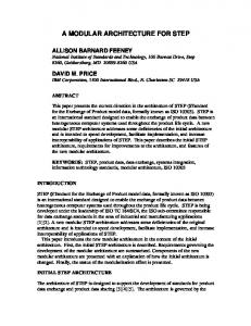
4. Functional Architecture VEIL is based in a fault-tolerant modular control architecture. Besides the x-by-wire functions, the vehicle also includes a set of support functionalities that implement the user interface and the global energy management. Figure 1 presents the ECUs needed to satisfy the vehicle requirements, including the data flows that each ECU produces and consumes.
The reminder of this section describes the different modules that compose the VEIL architecture, discussing its main functionalities and interactions. 4.1. Brake-by-wire The brake-by-wire system is responsible by transmitting the driver’s brake intention to the brake actuators positioned on each wheel. Electro-hydraulic brake-by-wire systems still use conventional hydraulic brake callipers at each wheel, but with the hydraulic pressure being controlled by one ECU. This system is composed by a brake pedal and associated angle sensor, and set of brake actuators composed by the park brake actuator, brake fluid pressure sensor and brake fluid hose, connected to the hydraulic brake calliper. The brake-by-wire system may also gather data from other subsystems, namely the wheel speed, steering angle, yaw rate and lateral acceleration sensors to determine the optimum amount of brake pressure to apply at each wheel, thus decreasing the braking distance and increasing the safety. Each wheel has an independent braking subsystem and the hydraulic pressure is applied independently on each wheel. The breaking system operates in two modes. Initially it is used the IM-VFD in regenerative braking mode, with the produced energy being collected by a super-capacitor to charge the batteries. When this actuation is not enough to reduce the vehicle speed at the rate desired by the driver, the electro-hydraulic actuators above described are activated. The system involves the use of two ECUs, one that senses the position of the break pedal (pos_brk signal) and other that implements the break strategy, namely the activation of the electro-hydraulic components, the amount of pressure to apply on each wheel and the implementation of the ABS (Antilock Braking System) algorithm. The individual control and sensing of each wheel is carried out by specific ECUs interconnected by a subnetwork. 4.2. Steer-by-wire The steer-by-wire system is composed by the steer wheel angle sensor, the steer wheel feedback motor, the pinion angle sensor (wheels angle) and the steering motor. This system is physically broken in two complementary subsystems, each managed by a distinct ECU. One of the subsystems is devoted to the steering wheel handling, namely the interface with the angle sensor (ang_sw signal) and control of the feedback motor, whilst the other subsystem interfaces with the road wheels sensor (ang_whl signal) and controls the steering motor.
Sub-network Pedal Brake
- Accelerator - Brake
pos_brk pos_acc
Bus
vel_veil
ang_sw
ang_whl
cur_im pos_brk vel_im ang_whl tmp_vfd
ang_whl
ang_sw
Steer wheel
DC/DC converter
IM-VFD
Road wheel
pos_brk pos_acc enb_vfd eng_bat tmp_bat
Battery Modules
vol_dch
Dashboard
cur_im vol_dch vol_dcl cur_dcl tmp_vfd enb_conv tmp_bat pwr sos aes
Solar Panel
eng_bat eng_sc vel_veil vel_im, aes
eng_sp
vol_dch eng_bat eng_sp eng_sc pwr sos
vol_dcl cur_dcl enb_conv enb_vfd
eng_sc
Super Capacitor
General Board
Energy Management System Sub-network
Figure 1: Functional distributed architecture for the VEIL electrical vehicle The system implements some desired control strategy as proposed in [6] with a set of filters that convert the hand wheel angle to torque applied to the steering system and a PD controller that tries to minimize the steering error between the hand wheel and the pinion angles. The simulation of this steer-by-wire architecture, without including the fault tolerance aspects, is presented in [13]. Currently the filters of the hand wheel node are partially implemented, only. 4.3. Accelerate-by-wire Most conventional internal combustion vehicles include a throttle position sensor (TPS) to provide input to diverse subsystems like traction control, ABS, etc., having a mechanical link to connect directly the pedal with the throttle control. In these cases, the throttle-bywire system replaces the mechanical link, using one ECU to compute the required throttle position from data measured by other sensors such as the accelerator pedal position, the engine rotation speed, the vehicle speed, etc. The throttle control is then driven to the required position by the ECU, typically using a closed-loop control algorithm. VEIL uses a similar architecture, but with the actuation carried out on the VFD instead of a throttle. For this reason the system is called the accelerate-bywire and is composed by the pedal position sensor, motor drive and electrical motor (Figure 2). The accelerator pedal sensor is attached to one ECU, which disseminates the pos_acc signal. The effective control of the motor is carried out by a dedicated ECU connected to the IM-VFD.
4.4. Dashboard panel The dashboard panel provides the driver with all the relevant information about the vehicle conditions. It is base on an intelligent device (a PalmOS, in the case) and can present both raw information (e.g. vehicle velocity, motor current, voltage of low-voltage dc-link, batteries energy, etc) as well as integrate the data to provide information like autonomy, trip length, average speed etc.
Pedal - Accelerator
pos_acc
IM-VFD
Bus
pos_acc
Figure 2: Electronic accelerator control It is also possible to set alarms related to some variables, e.g. when the battery energy lowers bellow a given threshold. 4.5. Energy Management System VEIL has several energy sources that require appropriate management. A specific ECU is devoted to control the energy flow between the sources – batteries, super capacitors and solar panels – and the motor, with the objective of maximizing the autonomy, assure functioning parameters within bounds (e.g. continuous control of batteries state of charge) and to provide maximum longevity of all subsystems.
4.6. Communication Requirements Steer and brake-by-wire functionalities are safety critical. Furthermore, many of the x-by-wire systems include close-loop controllers, which are particularly sensitive to jitter and end-to-end delays. For these reasons, it was decided to use the FTT-CAN protocol [4] as the communication infra-structure. The fault-tolerance aspects are addressed in the next section. Regarding the jitter and end-to-end delays, the use of a time-triggered protocol like FTT-CAN permits to impose phase control both on the system tasks and messages. With a proper analysis this level of control may be used to synchronize appropriately the several steps that each operation requires (e.g sampling, setpoint computation and actuation), thus minimizing the end-to-end delays. An illustrative example of the use of these features of the FTT-CAN protocol, applied to a middle-size soccer robot, can be found in [19]. In order to use FTT-CAN in VEIL it is necessary to identify the flow of messages between the ECUs, their priorities, periods, sizes and relative phasing. Table 1 presents these communication requirements. Different messages issued by the same node with the same activation period were piggybacked into a single message (column Frame ID in Table 1). The elementary cycle duration was set to 5 ms which is the shortest period among all periodic activities and messages. From the requirements stated in Table 1 results a bus load is close to 24% for a CAN at 250 Kbps, which is feasible.
5. Fault-Tolerant Modular Architecture This section presents the fault-tolerant hardware architecture and the underlying fault hypothesis. 5.1. Fault hypothesis The fault hypothesis considered is the following: • Node faults – both masters and slaves are assumed to exhibit fail-silence failure semantics. This means that they can only fail by not issuing any message to the network. For the masters, this assumption is substantiated by their internal redundancy. For the slaves, this assumption can hold if internal redundancy is also used, or, if bus guardians are used instead, the assumption is restricted to timing faults. • Channel transient faults – only transient faults that change the value of, at least, one bit are considered. Experimental data concerning CAN bit error rate [14] showed that CAN bit error rate in an -7 aggressive environment can be as low as 2.6x10 . Adapting the results of [15] to FTT-CAN, this value translates to at most 4 inconsistent message omissions per hour. Nevertheless, this work does not consider any particular constraint on the bit error rate nor on the duration of the error bursts but it is assumed that the resulting network
inaccessibility periods will not go beyond the physical controllability limit of the system. • Channel permanent faults – the transmission medium is a single point of failure of FTT-CAN and, thus, bus replication is mandatory to tolerate such faults. The bus replication mechanisms proposed in [17] are adopted, with the same message scheduling in the replicated buses. Notice that the possible bandwidth increase also proposed in [17] is not considered in this work. • Synchrony assumptions – it is assumed that nodes, both masters and slaves, are always synchronized. This assumption is based on the fact that the trigger message transmitted by the active master, besides conveying the scheduling information, also acts as a synchronization mark to all network nodes. That is, the master node is also the time master and it is assumed that in between two consecutive trigger messages (typically 5 to 10ms) the clock counters of each node do not diverge more than a negligible amount of time. In particular, bus guardians also have independent clock oscillators and synchronize on the reception of the trigger messages. As the synchronization requirements of FTT-CAN are relatively coarse, the assumption that masters and slaves are synchronized is assumed to hold even in the presence of error bursts that last for a relatively high number of consecutive ECs. The reader should refer to [16] for further details on the fault hypothesis and on some underlying properties of CAN and FTT-CAN. 5.2. Modular architecture The proposed architecture is based in FTT-CAN with replicated critical nodes and buses. Critical nodes are the ones implementing safety-related functions (x-by-wire) or the FTT-CAN master node. Non safety-critical nodes are not replicated but are also connected to two buses, to tolerate bus partition. The architecture also includes a gateway node that is necessary to configure the system at pre-run time. Once the system is running its parameters could be modified online, in a bounded, controlled and safe way, though requests issued to the master node by applications running in a slave node, as detailed in [18].
6. On going work Currently, the VEIL is already functional despite using a subset of the proposed systems. At the moment only the accelerate-by-wire system and the dashboard are fully integrated in the proposed architecture. The accelerate-by-wire system is capable of generating positive and negative accelerations, thus causing an electrical braking effect. The energy generated during braking will later be recovered by the super capacitors, which are not yet deployed.
Signal 1 2 3 4 5 6 7 8 9 10 11 12 13 14 15 16 17 18 19 20
Signal pos_brk pos_acc vel_veil cur_im vel_im tmp_vfd vol_dch eng_sp ang_stw ang_whl eng_bat tmp_bat pwr sos aes eng_sc vol_dcl cur_dcl enb_conv enb_vfd
Signal Description Brake position Accelerator position VEIL velocity Motor current Motor velocity VFD temperature High voltage DC-link voltage Solar panel energy Steering wheel angle Wheel angle (direction) Batteries energy Batteries temperature System power Emergency button Auxiliary electrical signals Super capacitor energy Low voltage DC-link voltage Low voltage DC-link current DC-DC converter enable VFD enable
Size [bytes] 1 1 1 2 2 1 2 2 2 2 2 1 1 1 3 2 2 2 1 1
T/mit [ms] 10 10 20 20 20 1000 20 1000 10 10 500 1000 250 100 50 100 100 500 500
Frame ID
Size [bytes]
From
f0
4
Pedal
f1
1
Brake
f2
4
f3 f4 f5 f6 f7 f8 f9 f10 f11 f12
1 2 2 2 2 2 1 1 3 2
f13
4
f14
2
IM-VFD DC/DC cnverter Solar panel Steer wheel Road wheel Batteries General board Super capacitor Energy management system
Table 1: Communication requirements Both the steer and brake-by-wire systems are still under development. The respective functions are currently carried out mechanically. The batteries, DCDC converter and solar panels are already installed but still operating autonomously. The whole system is expected to be fully functional in the near future, which will allow validating the proposed architecture under real operating conditions.
References [1]
[2]
7. Conclusion Small electrical vehicles present a set of interesting features, like a reduction on air pollution, increase mobility in urban areas, higher energy efficiency, higher economy, etc. On the other hand, the adoption of x-bywire technologies brings sizeable benefits to the automotive systems, permitting important weight and cabling reduction, increased flexibility and maintainability and has the potential to permit a more efficient energy usage, with a noticeable impact on the operational costs and pollution reduction. The paper proposes a modular distributed architecture with fault tolerant modes able to support x-by-wire functions, namely steer-by-wire, brake-by-wire and accelerate-by-wire, to be used in small electric vehicles. The FTT-CAN protocol is used as the communication infrastructure, serving both communication and task synchronization purposes. The main contributions of the paper are the description of the vehicle architecture, the communication requirements and the discussion of the fault-tolerant architecture.
[3] [4]
[5]
[6]
[7]
[8]
F. Santos, J. P. Trovão, L. Marques, “Modelling and Simulation Results for the VEIL Electric Vehicle”, in Proc. 9CHLIE – 9º Congresso Hispano-Luso de Eng. Electrotécnica, 2005 “X-by-wire – safety related fault tolerant systems in vehicles (final report), “ X-by-Wire Project, BriteEuRam 111 Program, Rep. No. XByWire-DB-6/6-24, 1998. Laprie, J.C. (1992). Dependability: Basic Concepts and Terminology. Springer-Verlag. Almeida, L., Pedreiras, P. and Fonseca, J. A. The FTTCAN protocol: Why and how. IEEE Transactions on Industrial Electronics, Volume 49, Issue 6, Dec. 2002, pp. 1189-1201. Almeida, L., Marau, R., Fonseca, J.A., Ferreira, J. and Silva, V. (2006). Assessment of FTT-CAN Master Replication mechanisns for Safety-Critical Applications. SAE 2006 World Congress, Detroit, MI, USA. Yih, P. and Gerdes, J. C. (2005). Modification of Vehicle Handling Characteristics via Steer-by-Wire. In IEEE Transactions on Control Systems Technology, vol. 13, no. 6, pp. 965-976, Nov. 2005. Society of Automotive Engineers (SAE) public discussion: 42 Volt Electrical Systems and Fuel Cells : Harmonious marriage or incompatible partners?, SAE (N.Traub), General Motors (Ch.Borroni-Bird, Director of Design and Technology Fusion), Delphi (J.Botti, Innovation Center), Daimler Chrysler (T.Moore, Vice President, Liberty and Technical Affairs), UTC Fuels Cells (F.R.Preli, Vice President, Engineering), SAE 2003 World Congress & Exhibition, Detroit (USA), 2003. Kelling, N. A. and Heck, W. The BRAKE Project – Centralized Versus distributed Redundancy for Brake-
[9] [10]
[11]
[12]
[13]
[14]
by-Wire Systems. SAE Congress, Detroit, Michigan. SAE2002-01-0266. LangenWalter, J. and Kelly, B. (2003). Virtual Design of a 42V Brake-by-Wire System. SAE Congress. Jang, S-H., Park, T-J., Han, C-S. A Control of Vehicle using Steer-by-Wire System with Hardware-in-the-Loop Simulation System. IEEE/ASME International Conference on Advanced Intelligent Mechatronics (AIM 2003). Amberkar, S., Bolourchi, F., Demerly, J., Millsap, S. A Control System Methodology for Steer-by-Wire Systems. SAE Congress 2004, Detroit, USA. Pimentel, J. R. An Architecture for a Safety Critical Steer-by-Wire System. SAE Congress 2004, Detroit, USA. Santos, M. M., Almeida, L., Fuertes, J. P. Using DualRate Switching Control in Steer-by-Wire Application. th 12 IFAC Symposium on Information Control Problems in Manufacturing - INCOM 2006. Saint-Etienne, France. May 17-19, 2006. J. Ferreira, A. Oliveira, P. Fonseca, and J. A. Fonseca, “An experiment to assess bit error rate in CAN,” RTN 2004 - 3rd Int. Workshop on Real-Time Networks satellite held in conjunction with the 16th Euromicro Intl Conference on Real-Time Systems, June 2004.
[15] J. Rufino, P. Veríssimo, G. Arroz, C. Almeida, and L. Rodigues, “Fault-tolerant broadcast in CAN,” Digest of Papers, 28th International Symposium on Fault Tolerant Computer Systems, pp. 150–159, 1998. [16] G. Rodríguez-Navas, J. Proenza, J. Rigo, J. Ferreira, L. Almeida, and J. Fonseca, “Design and Modeling of a Protocol to Enforce Consistency among Replicated Masters in FTT-CAN,” Proceedings of the 5th Workshop on Factory Communication Systems (WFCS 2004), pp. 229– 238, 2004. [17] V. F. Silva, J. A. Fonseca, “Using FTT-CAN to combine redundancy with increased bandwidth”, In Proceedings of 2006 IEEE International Workshop on Factory Communications Systems, pp. 55-63. [18] J. Ferreira; L. Almeida; J. A. Fonseca; P. Pedreiras; E. Martins; G. Rodriguez-Navas; J. Rigo; J. Proenza. “Combining Operational Flexibility and Dependability in FTT-CAN”. IEEE Transactions on Industrial Informatics, 2(2):95-102, May 2006 [19] Silva, V., R. Marau, L. Almeida, J. Ferreira, M. Calha, P. Pedreiras, J. Fonseca. "Implementing a distributed sensing and actuation system: The CAMBADA robots case study". ETFA 2005, T8 Intelligent Robots and Systems Transaction.