Nukleaire diagnostiek is een medische techniek waarbij een radioaktieve ... dit proefschrift worden de fysische achtergronden van het boven beschreven.
A new gamma camera for Positron Emission Tomography
P. SCHOTANUS
v)
Ur\ A new gamma camera for Positron Emission Tomography
A new gamma camera for Positron Emission Tomography PROEFSCHRIFT
TER VERKRIJGING VAN DE GRAAD VAN DOCTOR AAN DE TECHNISCHE UNIVERSITEIT DELFT, OP GEZAG VAN DE RECTOR MAGNIFICUS, PROF.DRS. P.A. SCHENCK, IN HET OPENBAAR TE VERDEDIGEN TEN OVERSTAAN VAN EEN COMMISSIE, AANGEWEZEN DOOR HET COLLEGE VAN DECANEN, OP DINSDAG 20 SEPTEMBER 1988 TE 16.00 UUR.
DOOR PAUL SCHOTANUS DOCTORANDUS IN DE NATUURKUNDE GEBOREN TE EINDHOVEN
TR diss 1659
Dit proefschrift is goedgekeurd door de promotor Prof.dr. A.H. Wapstra
Sommige boeken schijnen geschreven te zijn,niet opdat men er iets uit zou leren, maar opdat men weten zal, dat de schrijver iets geweten heeft.
Goethe
Contents page
1 Introduction
1
2 Nuclear diagnostics as a tool in medical science; principles and applications 2.1
The position of nuclear diagnostics in medical science
2
2.2
The detection of radiation in nuclear diagnostics:
5
standard techniques 2.3
Positron emission tomography
7
2.4
Positron emitting isotopes
2.5
Examples of radiodiagnostic studies with PET
11
2.6
Comparison of PET with other diagnostic techniques
12
9
3 Detectors for positron emission tomography 3.1 The absorption of 511 keV annihilation radiation in solids
15
3.2 Scintillators for the detection of annihilation radiation
21
3.3 The detection of scintillation light
23
3.4 Alternative ways to detect annihilation radiation
28
3-5 Determination of the point of annihilation: detector geometry,
31
scatter and their influence on the image quality 3.6 The use of Time-of-Flight information: TOF PET
35
3.7 The performance of a PET camera
36
3-7-1 Position resolution 3.7.2 Sensitivity 3.8 Examples of positron camera systems
36 39 40
4 The solid scintillator proportional counter, an alternative approach 4.1 History and basic principles
45
4.2 Barium fluoride as a UV scintillator
46
4.3 Photosensitive vapours and liquids: TMAE
47
4.4 Low pressure wire chambers
51
4.5 Solid scintillator proportional counters: operation principles
57
Paper I: Photoelectron production in BaF_-TMAE detectors 4.6 The SSPC as a gamma camera for PET
58 64
5 Detection of 511 keV annihilation radiation with a solid scintillator proportional counter: experiments and results 5.1
5.2
Experimental procedures and methods
65
5.1.1 The multiwire chamber
65
5.1.2 Position readout
68
5.1.3 Choice of detector materials
71
5.1.4 Electronics
72
5.1.5 Gas system, TMAE supply
73
5.1.6 Measuring procedures; tests of the MWPC
75
Experiments with liquid TMAE
77
5.2.1 Design of the test detector
77
5.2.2 UV detection in TMAE
78
5.2.3 Scintillation light detection with liquid
8l
TMAE layers 5.3
5.4
Detection of annihilation radiation in an SSPC, results at 20
C
5.3.1 Energy and time resolution studies
84
5.3.2 Position determination at 20 C
85
Experiments at elevated temperatures
5.6
5.7
88
5.4.1 Experiments with an 8 mm diameter BaF_ crystal
89
5.4.2 Experiments with the 150 mm diameter BaF_ crystal
90
Paper II: A BaF_-MWPC gamma camera for Positron Emission Tomography 5-5
82
Performance of the final detector
95. 1Q3
5.5.1 Gas amplification
103
5-5-2 Sensitivity of the detector as a function of energy
105
5.5.3 Time resolution
108
5-5-4 Position spectra at 55 °C
109
Efficiency improvement by addition of another scintillation crystal
113
5.6.1 The influence of radiation scattered in the object
116
5.6.2 High count rate behaviour, ageing
117
Implementation of the SSPC in a PET detector
119
6 Scintillator research 6.1
Luminescence of inorganic solids
122
6.2
Barium fluoride luminescence: "crossover transitions"
127
6.3
Scintillation properties of BaF
130
6.3-1 Experimental procedures
131
6.3-2 Measuring results
134
Paper III: Temperature dependence of BaF_
135
scintillation light yield 6.4
La
doping of barium fluoride crystals
144
6.5
Pb
doping of barium fluoride crystals
150
Paper IV: The effect of Pb
contamination on BaFp
151
scintilation characteristics Paper
V: Luminescence of the divalent lead ion in
l60
barium fluoride crystals 6.6
Scintillation characteristics of other alkaline-earth fluorides
166
6.7
Ultraviolet luminescence of-rare earth doped fluorides
170
6.7-1 Neodymium doped lanthanum fluoride
171
Paper VI: Detection of LaF,:Nd^+ scintillation light
172
in a photosensitive multiwire chamber 6.7-2 Neodymium doped barium-yttrium-fluoride 7 Conclusions
182 184
Acknowledgements
186
References
187
Summary
194
Samenvatting
197
Curriculum Vitae
200
1
INTRODUCTION
Nuclear diagnostics is a non-invasive medical technique to examine the functioning of organs and to detect abnormalities. In it, radioisotopes are introduced in the body, usually in the form of chemical compounds labeled with a suitable radioactive element; the chemical compound is selected on basis of its function in the process of interest. By measuring the radiation emitted by the label outside the body, a 'functional image can be obtained. The technique is used in most hospitals next to other non-invasive diagnostic techniques such as computerized tomography and ultrasound imaging. The instrument to measure the radioactivity distribution is called a gamma camera, since usually gamma radiation emitting radionuclides are used. The most frequently applied type of gamma camera consists of a crystal, in which the absorption of radiation produces light (scintillations), and a number of light detectors to determine the-position of the absorption. Common gamma cameras supply a two dimensional projection of the radioactivity distribution. When two opposing gamma cameras are used to reconstruct a three dimensional image from a number of projections, the technique is called SPECT (Single Photon Emission Computerized Tomography). Positron Emission Tomography (PET) is another in-vivo tracer technique that makes use of the annihilation of positive electrons emitted by radioisotopes. This results in two almost collinear gamma quanta with an energy of 5 H keV. By labeling compounds with positron emitters and by measuring the coincident emitted gamma radiation, a true three dimensional image of the distribution of the radioactivity can be obtained. The technique offers the unique possibility to determine quantitatively the uptake of a certain compound. It can be used to measure metabolic processes because of its high sensitivity and because the "biological" elements carbon, nitrogen and oxygen all have convenient positron emitting isotopes. Gamma cameras for PET have to satisfy special requirements because of the high energy of the radiation and because the selection of coincident events must be possible. Also, most suitable positron emitters have such short half lives that they have to be produced in the hospital itself. This, together with the rather complicated technique of the synthesis of the labeled compounds, makes PET a multidisciplinary technique. The configuration of a set of gamma cameras to register a tomographically
- 1-
reconstructed image is called a PET scanner. In the last few years, a considerable improvement in the position resolution of PET scanners has been achieved by reducing the size of the scintillation crystals and by applying high density scintillation materials. This, however, has decreased their detection efficiency and has increased their cost and complexity. Presently, there is a need to increase this efficiency without loss of resolution. This requires a different concept of gamma camera. In this work, a new type of gamma camera consisting of a high density scintillator (barium fluoride (BaF )) in combination with a light sensitive wire chamber is presented. This type of detector, which is, up to now, only used for the detection of high energy particles, offers several advantages compared to conventional systems. Furthermore, rather inexpensive technology is used. Thus, the cost of a PET scanner can be reduced significantly. The aim of this research is to explore the physical mechanism of gamma radiation detection using this new principle, and to investigate whether this approach is suitable for application in a medical PET scanner. The first part of this work describes the operation and performance of this new gamma camera, the second part is focussed on the scintillation mechanisms in BaF_. Also a study to investigate ultraviolet scintillation of other fluorides has been conducted. The first part of this work is organized as follows: chapter 2 describes the place of PET in nuclear diagnostics and its advantages and limitations compared to other diagnostic techniques; also some examples of radiodiagnostic studies with PET are presented. Chapter 3 discusses the requirements and performance characteristics of a PET scannner and gives some examples of operational systems. In chapter 4, the theoretical aspects of the above described new way of gamma radiation detection are presented. The results of our experiments with this new gamma camera are presented in chapter 5 together with a list of expected performance characteristics of a future PET scanner. The second part of this thesis (Chapter 6) is dedicated to research on scintillators. The theoretical aspects of solid scintillators together with some recent results on BaFp are discussed. Finally, a new generation of UV scintillation materials for detection of gamma radiation in combination with light sensitive wire chambers is introduced.
- 2 -
2
NUCLEAR DIAGNOSTICS IN MEDICAL SCIENCE; PRINCIPLES AND APPLICATIONS
2.1 THE POSITION OF NUCLEAR DIAGNOSTICS IN MEDICAL SCIENCE Nuclear diagnostics has become an important technique for in-vivo examination of the functioning of organs and for the study of a great number of physiological processes in the human (or animal) body. It comprises the introduction of a radioactive substance into the body after which the spatial distribution, flow or uptake by a certain organ is measured externally by observing the emitted radiation. In general, use is made of a carrier molecule which is accumulated or metabolized in the organ to be studied, and which is labeled with a suitable radionuclide to form a radiopharmaceutical); in this way, the distribution of the compound can be studied. Nuclear diagnostics must be seen along with other in-vivo diagnostic techniques such as Computerized Tomography (CT), ultrasound imaging and Magnetic Resonance Imaging (MRI). The CT technique uses an external radiation (X-ray) source to measure density profiles which are used to reconstruct a three dimensional density image. Ultrasound imaging uses reflections of ultrasound waves caused by a gradient of acoustic impedance whereas with MRI the distribution of certain non-zero spin nuclei can be measured. These other diagnostic techniques will be discussed briefly in section 2.6. The disadvantage of nuclear diagnostics is the fact that (part of) the body is subject to ionizing radiation which can cause cell damage (e.g. mutations) but often the technique offers the only possibility to obtain early information about a suspected abnormality or malfunctioning. The number of radionuclides usable as a label in nuclear diagnostics is limited by the decay mode (alpha-, beta-, or gamma-rays), energy, and halflife. Because of the high local ionization properties of alpha particles, the use of nuclides decaying by alpha emission is out of the question. Mostly nuclides emitting gamma radiation are used. Of these, nuclides decaying by electron capture with subsequent emission of gamma-rays with energies between 50 and 400 keV are frequently used. Sometimes, before decaying to the ground state, the parent nucleus decays to an isomeric or metastable state under emission of gamma radiation. An example of this is 99 99m Mo which is the parent nucleus of Tc. The energy of the emitted radiation should not be too small since otherwise the radiation cannot be
-3 -
detected outside the body (say E
> 50 keV). Also, the combination of
physical half-life of the radioactive label and biological half-life of the radiopharmaceutical must be small to limit the radiation dose administered to the patient as much as possible. In practice, physical half-lives range between about a minute and a week. Most nuclides used for diagnostic purposes can be produced with a nuclear reactor; some of these have to be produced with a particle accelerator. Table I summarizes a few radionuclides commonly used for standard diagnostic studies together with their half-life and principal gamma-ray energy.
Table I. Some commonly used radionuclides. Radionuclide 99m Tc 8lm
Kr 123.,. 67
half-life
ET (keV)
6.02 h
140.5
13-3 13.0
s
190.7
h
158.9
Ga
3.26
d
1U
In
2.83
d
1 7 1 . 3 ; 215.4
201
T1
3.06
d
6 8 . 9 ; 7 0 . 8 ; 80.2 (K X-rays)
8.04
d
135-3; 167.4 364.4
131 Z
9 3 - 3 ; 181.6; 300.2
The most commonly used radionuclide for medical imaging is
I'C. It is
readily available from a generator system (combination with a parent nuclide having a longer half-life than the daughter) and can fairly easy be chemically bound to a great number of compounds. For detection of tumours in 99m the bone, e.g. Tc-methyleen-diphosphonate can be used: the tumours show up as "hot spots" (regions of enhanced uptake of the radiopharmaceutical). With the so-called perfusion method, the blood circulation in the lungs 99m can be measured: a suspension of Tc-albumine particles (10~50um diameter) is administered to the blood stream. The particles temporarily block the capillary vessels of the lungs. Cold spots are correlated with poorly perfused parts of the lungs due to e.g. a thrombus. Fig.1 shows examples of a two-dimensional radioactivity distribution in the lungs recorded this way.
-4 -
Using the ventilation method, where e.g.
Kr gas is inhaled (on a
continuous basis because of its short half-life) the ventilation of the lungs can be measured providing additional information.
Fig.1.
Two dimensional radioactivity distribution (scintigram) of
the lungs, showing the lung perfusion. The left figure represents the normal situation; in the right figure, an obstruction (probably a thrombus) is present in a blood vessel. Courtesy of Dr. C. Vandecasteele, Institute of Nuclear Sciences, Gent, Belgium. A few other examples of radiodiagnostic investigations: recordings of the liver, where "cold spots" are associated with areas with a decreased Kupffer cell function, and measurements of the brain perfusion: when the Blood-Brain Barrier is disturbed because of infections or tumours, the distribution of the nuclide becomes inhomogeneous.
2.2 THE DETECTION OF RADIATION IN NUCLEAR DIAGNOSTICS: STANDARD TECHNIQUES The standard device for the imaging of radionuclides is the scintillation camera or gamma camera. In this instrument, also called Anger camera after its inventor [1], gamma radiation is absorbed in a scintillation crystal, often Nal(Tl), resulting in the production of light flashes. The crystal with a diameter between 25 and 50 cm is optically coupled to an array of photomultipliers to detect the scintillation light (Fig.2). The light distribution over the different photomultipliers determines the point of interaction in the scintillator. The energy of the absorbed radiation can also be selected. To obtain a one-to-one image of the object on the
-5 -
'ILlilinl
scintillation crystal
^ffyparcllel
hole collimator
gamma source
Fig.2.
The construction of a scintillation camera, Paans [2],
scintillator, a collimator is mounted in front of the crystal. This collimator consists of a slab of lead with a great number of parallel holes, that only transmit radiation entering perpendicular to the crystal surface. The wall thickness (septum) between the holes depends on the energy of the radiation to be measured. Because of the collimator, the sensitivity of the device is very low: the transmission of the collimator is of the order of ID"4. With an Anger camera only projections of the three-dimensional activity distribution can be measured. By measuring projections under different angles with respect to the object (rotation of the camera), a reconstruction of the activity distribution can be made by using mathematical image reconstruction methods. This method is known as Single Photon Emission Computerized Tomography (SPECT). Some systems use two opposing cameras to increase the efficiency. The disadvantage of SPECT is that it does not allow to make accurate corrections for the attenuation of radiation in the body, since the body density and the activity distribution are not a priori known. With the use of models for the depth and density of organs, quantitative numbers for the absolute uptake of the radiopharmaceutical can be deduced, but only with an error in the order of at least 10 % [2]. As the distance from the collimator increases, the spatial resolution of a standard gamma camera decreases because of the fixed finite hole size of a collimator; this leads to unsharp images; SPECT does therefore not produce very good images of deeper lying organs. As the energy of the radiation increases, thicker septa are needed which leads to image artefacts (the image of the septa on the crystal is visible). This is a problem at energies larger than about 400 keV. At low gamma
-6 -
energies (< 50 keV) the attenuation in the body becomes a problem and, since the amount of photons produced in the scintillator is proportional to the energy of incident radiation, the statistical error associated with the light detection process in the photomultipliers leads to a degradation of the position resolution. The process of absorption and subsequent production of photons in a scintillator will be discussed in detail in section 3-1Because of the above, standard gamma cameras function optimally at gammma energies between 100 and 200 keV. Routine radiodiagnostical investigations using Anger cameras supply important information. The method is relatively inexpensive because the radionuclides used are off-the-shelf items and no expensive equipment besides the gamma camera itself is required.
2.3 POSITRON EMISSION TOMOGRAPHY.
For the in-vivo study of the distribution of biologically active compounds with nuclear diagnostics, one is confined to the "biological" elements carbon, nitrogen and oxygen (+ hydrogen). Metabolic processes, dealing with the chemistry in the body, can only be studied with nuclear diagnostics using isotopes of the above mentioned elements. These elements, however, have only convenient isotopes that are positron emitters. The primary fj radiation that these nuclides emit cannot penetrate far in tissue. The positron range amounts to a few millimeters; it depends on the energy of the |3 particles. When a positron has slowed down in the surrounding material to nearly rest, it will annihilate with an electron. In this process, the total mass is converted into electromagnetic energy 2 according to E=mc ; in most cases two-photons with an energy of 511 keV each are emitted under -180 . Because of the kinetic energy of the electron, the momentum of the center of mass of the two-body system is not zero. This results in a small spread in the angular distribution of about 0.5
around
the mean angle of 180 . The 511 keV annihilation radiation cannot well be used for conventional imaging with an Anger camera because radiation of this energy is difficult to collimate. Positron emission tomography (PET), however, exploits the collinear emission of the annihilation quanta by putting a coincidence requirement on detectors which are opposing each other: an event detected simultaneously in the two detectors means that the annihilation took place somewhere along the line between the two points of detection. Fig.3
- 7 -
Fig.3.
Principle of a positron camera.
illustrates the principle. From the coincidence data, images can be reconstructed which represent the three dimensional distribution of radioactivity. To obtain quantitive information, the images have to be corrected for attenuation of radiation in the body and for the response function of the detector. As remarked earlier, it is in principle not possible with SPECT to correct accurately for attenuation. In PET, however, the probability of escape of both 511 keV quanta only depends on the total density of the absorber along the line defined by the..coincidence in the two detectors. Therefore, transmission measurements with an external positron source supply the information required for a quantitative determination of the uptake or distribution of a certain radiopharmaceutical. Another advantage of PET is the fact that the detection efficiency of the radiation can be large because the collinear emission eliminates the need of inefficient (lead) collimators. Also, most positron emitting nuclides used in medicine have a very short half-life (cf. Tables I and II) and therefore, with the same amount of activity administered to a patient, the radiation dose can be reduced significantly. In interpreting the data obtained from a PET study, a concentration of a radiopharmaceutical in a certain place in the body has to be "translated" to a parameter of the metabolic process one wants to examine. For this purpose, so-called tracer kinetic (mathematical) models are used.
-8 -
2.4 POSITRON EMITTING ISOTOPES Radionuclides decaying by positron emission are neutron deficient. They can be produced by removing one or more neutrons from a stable nucleus. The most simple way to produce positron emitters is by a charged particle
Table II. List of the most important radio isotopes used in positron imaging and some examples of their application ( 2,4,5). Isotope
T 1/2
11 C
E max (MeV) U+
20.4 min
13N
9.96
min
0.961
I.19
labeled substance 11
co, 1 1 co P .
example of use heart blood volume
C-glucose, 11 C-palmitic acid 11, , C-dopamxne C-putrescine
brain metabolism
13 NH„
heart blood flow
heart metabolism neurotransmitter tumour metabolism
blood flow 13N 0 2 150
2.04 min
18 F
68
109.8 min
Ge- 68 Ga 68.1 min
1.73
0.635
1.90
(generator)
c 15 o, c 1 5 o.
brain blood flow
15n
oxygen consumption
18 F-deoxy-glucose 18 F-fluorodopa
68,Ga-EDTA Ga
glucose metabolism neuroreceptor liver function transmission meas. + calibration of the PET-scanner
82
Sr- 82 Rb 1.3
3.1
82 Rb-ion
heart blood flow
(generator) I
4.2 days
2.13, 1-53
I-ion
thyroid studies
induced reaction using e.g. a cyclotron delivering beams of energetic protons, deuterons, or other charged particles. Details about this process are discussed in ref.[3]. Table II gives a list of the most frequently used positron emitters for radiodiagnostic PET studies together with their halflife, positron end-point energy and a few examples of labeled substances together with some applications. A few positron emitters can be obtained from a so-called generator system. This is a relatively long-living radionuclide (produced with a cyclotron) which decays into a short living nuclide which can be separated from the mother nuclide by elution (washing out with a suitable chemical). For the use of these kind of positron emitters in radiodiagnostic centers an "on-the-spot" cyclotron is not needed. (TO
£0
Ge-
On
Ga and
Examples are the generator systems
Qp
Sr-
Rb. The half-life of the respective mother nuclides is 1 ft F, which has a half-life of over an
288 days and 25 days. Apart from
hour and can be transported from the production site to the place where it is needed, the use of all other positron emitters in Table II requires a cyclotron in the radiodiagnostic center itself. The change of element in the production of positron emitters is a very important aspect, since it allows so-called carrier-free production. This means that after the irradiation e.g. all carbon will in principle be carbon-11. In practice this is very hard to achieve since dilution with stable carbon-12 occurs very easily. However, very high specific activities (Ci/mol) are possible, even with complex molecules [ 5 ] . An isotope concentration of 1 : 1 0 - 1 0
stable atoms can be achieved. This means
that only very small quantities of radiopharmaceuticals (of the order of 10 nmol) are sufficient for a radiodiagnostic study, corresponding with about 10 mCi of activity. The influence of the radiopharmaceutical on the metabolism is then negligible. The synthesis of the required radiopharmaceuticals labeled with shortliving positron emitters has to take place close to the place of production. Recently, compact automated radioisotope delivery systems have become available for hospital use [ 6 ] . Further development and application of these systems would greatly facilitate the routine use of PET in hospitals.
- 10 -
2.5 EXAMPLES OF RADIODIAGNOSTIC STUDIES WITH PET
In this section selected examples are given of radiodiagnostic studies with PET with the intention to illustrate the possiblities of the technique.
Neurology For brain research, PET can be used to measure changes in regional blood volume and metabolism and to obtain information about neurotransmitters and receptors. The glucose metabolism decreases for example with Alzheimer's dementia whereas tumours are often correlated with a high local glucose consumption. 18 The glucose metabolism can be measured with FDG (Fluoro-deoxyglucose) or 11 C-glucose [7]. Fig.4 shows an example of a PET scan demonstrating the local glucose consumption.
FOG
HCÏ/CC 458
NORMAL
#** at* rift» 0k jOGt «H%
JÉJIA
ffeif
n&^^^ua^^'
TKaKSJHSBSBaffft
^aslïï&£&3yililA
KFA JUELICH
m£ÊÈ IBBro^wli'
f ÉlüJ *!Ü^IS§&^^B1&«|3Ï
SCANDITRONIX PC4896 1 ft
Fig.4.
PET-scan showing the glucose distribution { FDG) in the brain of a
normal volunteer. Holte et al. [54]. Courtesy of Prof.Dr. L. Feinendegen, Institute of Medicin, Nuclear Research Center, Jülich, Germany.
11
C O
,C
0 ? and
CO are used to examine the cerebral blood flow which can 15 give information about strokes; inhaled 0_ allows measurement of the local oxygen consumption of the brain. The study of neurotransmittors and iO
receptors labeled with
11
F or
C can e.g. provide a better understanding
of Parkinson's disease [ 8 , 9 ] . Cardiac studies Using PET, heart function, blood flow and vitality can be determined. 1Q
With diffusable tracers such as
ft?
NH_ and
RbCl it is possible to measure 1 ft the myocardial blood flow [ 1 0 ] . Together with examinations using FDG and 11 C labeled palmitic acid to measure the metabolism, important conclusions can b e drawn about the vitality of the heart tissue after an infarct [ 1 1 ] .
Oncology The metabolism of tumours can provide insight into their malignancy and growth rate. The effect of a therapy can be followed by comparing the metabolic activity before, during and after a certain therapy. PET can also be used to evaluate chemotherapy and radiotherapy protocols. 0xygen-15 labeled molecular oxygen is used to study the oxygen demand of tumours whereas their growth rate can be measured using certain amino acids such as C-putrescine [ 1 2 ] . These are only a few examples.
Thyroid studies Using iodine isotopes, the metabolism of the thyroid can be measured. Since with PET a three dimensional image of the thyroid gland can be recorded, abnormalities in size and dimension become apparent. Studies using 124 the positron emitter I have demonstrated that certain abnormalites of the thyroid are correlated with a heterogeneity of the iodine distribution with marked hot and cold spots [13]- By measuring the functional thyroid volume, the necessary dose for e.g. radiotherapy can be determined.
2.6 COMPARISON OF PET WITH OTHER DIAGNOSTIC TECHNIQUES
Positron Emission Tomography is only one of the medical diagnostic techniques that use some kind of radiation to observe processes and structures in-vivo in the body. In this section, a few aspects and specific applications of PET and other in-vivo diagnostic techniques will be
- 12 -
discussed. All methods have their own specific applications, advantages and disadvantages. Positron Emission Tomography (PET) As shown in the previous section, PET provides information about metabolic processes in the body. It is possible to measure a three dimensional distribution of a certain compound without having to change the chemical composition to such an extent that the tracer itself will influence the metabolism. This is due to the high sensitivity of the method. Since most positron emitters have a very short half-life, the amount of radioactivity administered to a patient is relatively low compared to a standard nuclear diagnostic investigation. Because of the collinear nature of the annihilation radiation, absolute quantification is possible. The disadvantage is the complexity of the method and the fact that a cyclotron is needed for the production of the positron emitters. However, standard automated radioisotope delivery systems installed in hospitals would greatly facilitate the synthesis of radiopharmaceuticals whereas generator produced positron emitters like
Ga and
Rb can be used without the need of
expensive equipment. The PET scanner itself, which has to detect the 5 H keV annihilation radiation, is still a rather complex and expensive device. The use of PET would be greatly stimulated when these drawbacks could be eliminated. Single Photon Emission Computerized Tomography (SPECT) This technique, employing a standard gamma camera, has already been discussed in detail in section 2.2. It is widely applied and most radioisotopes are available as off-the-shelf items. The sensitivity is rather low (two to three orders of magnitude smaller than PET), and the gamma emitters used have a half-life in the order of many hours. Absolute quantification is difficult and the position resolution for deeper lying organs is not so good.
Computerized Tomography (CT) CT measures the transmission of X-ray radiation through the body produced by an external X-ray generator. Using a great number of transverse transmission profiles, the three dimensional density distribution can be determined. For this purpose, a great number of computer reconstruction algorithms has been developed. The technique is fast and enables the
- 13 -
discrimination of contrast differences of about 0.5 %• Stuctural abnormalities in e.g. the brain can be detected with a spatial resolution of the order of a millimeter which yields excellent anatomical information. With CT, differences in density are measured, not in functioning as with PET. The disadvantage of the method is the relatively high radiation dose per investigation. Ultrasound imaging This diagnostic technique uses the reflection of ultrasound waves on boundaries between tissues. It gives structural anatomical information but small differences in density cannot well be discriminated. Using the doppler effect, blood flow profiles in arteries can be measured. This diagnostic method is widely used for a great number of applications since no harmful side effects have been found yet. Magnetic Resonance Imaging (MRI) This diagnostic technique has been given much attention in the last few years. MRI, also called NMR (Nuclear Magnetic Resonance) takes advantage of the spin of protons in water molecules to measure both their number and relaxation times in-vivo. By applying strong external magnetic fields (in the order of one Tesla) and radio frequency (rf) excitation fields, the rf radiation emitted by nuclei with non-zero spin is detected. Without moving the patient, tomographic images of any plane in the field of view can be constructed. The method gives in the first place morphologic images of the water and fat distribution in the body. Although MRI is not very sensitive it gives images with a very good resolution (of the order of a millimeter).■13 It can in principle also be applied to other non-zero spin elements like C, 19 23 31 F,
Na and
P, but since their concentration in the body is much smaller
than that of protons, the sensitivity of these measurements is also lower [5]. The study of metabolic processes with MRI is therefore difficult. An advantage of MRI is the fact that the investigation does not have any negative effect on the patient at least not with the current values of the applied magnetic field (< 2 Tesla). A disadvantage of the method is the fact that the equipment required is rather expensive.
- 14 -
3
DETECTORS FOR POSITRON EMISSION TOMOGRAPHY
In Positron Emission Tomography, the point of annihilation of a positron must be determined as accurately as possible. Next to a good position resolution, a detector for PET must have a good detection efficiency. The maximum amount of activity administered to a patient is limited by the maximum permissable dose. It is desirable that the largest possible number of annihilation events is detected per amount of administered activity. Also, the data must be collected in a short period of time since most positron emitters have a short half-life. Therefore, PET detectors must be able to cope with high count rates and must have small dead times. Furthermore, as will be demonstrated, energy and time discrimination by the detector is essential to obtain good quality images. In this chapter a theoretical description of the detection of annihilation radiation will be given and requirements for PET detectors will be discussed. As will be shown, geometrical considerations play an important role in the performance of a PET detector. Finally, some examples will be given of existing detector systems.
3.1 THE ABSORPTION OF 511 KEV ANNIHILATION RADIATION IN SOLIDS Electromagnetic radiation (photons) interacts with matter mainly by three processes: 1. Photo-electric effect, 2. Compton effect, 3. Pair production. In the photo-electric effect, the photon is absorbed by an atom and subsequently an electron (photoelectron) from one of the shells is ejected. This electron, originating mainly from the K-shell, is emitted under an angle 8 with an angular distribution which depends on the energy of the incident photon. Fig.5a illustrates the process. The angular distribution has its maximum at 90
at low photon energies (several keV), and shifts
to more forward angles if the energy is increased while the distribution then gets narrower. The photoelectron acquires an energy (E ) equal to pe the difference between the photon energy hv and the binding energy E, of the electron. E = hv - E. pe b
(3.1) '
u
- 15 -
F i g . 5 a . Schematic r e p r e s e n t a t i o n of t h e p h o t o - e l e c t r i c p r o c e s s . e~ (photoelectron)
The energy E, subsequently appears in the form of characteristic X-rays or Auger electrons from the filling of the vacancy created by the ejection of the photoelectron. For 511 keV photons, the range of the photoelectrons in solids amounts to a fraction of a millimeter so that in the photo-electric process the complete energy of the incident photon is absorbed in the solid. In the Compton effect, the photon interacts with an atomic electron and part of the energy of the photon is transferred to this electron. The result is a Compton scattered photon with energy hv' and a so-called "Compton electron" with energy E . The energy distribution depends on the angle 9 between the direction of the original photon and the scattered one. Fig.5b illustrates the proces. Compton electron Incident photon Ji»>0=a (m 0 c 2 >
Atomic electron
F i g . 5 b . Mechanism of Compton interaction.
Compton scattered photon
hv' From c o n s e r v a t i o n of momentum and energy, the following equations can be derived: E T , = EY / {1 + a ( l - c o s 9 ) } with
a=
E / m c
= E
(3-2)
/ 511 keV
The angle ♦ of the Compton electron is given by: cotan$ = (l+a)tan{9/2}.
(3-3) - 16 -
140"
130"
120"
110"
100"
90"
80"
70"
60"
50"
40"
150"
N.
^^Q~0JTH0MS0N)
160"
170°
7V£*T=5"=ioV-' ^ r > ^ r " Ja i
W T T |4 , ]6 ^ 8 5>^/——___ 1 CROSS SECTI0N*J
DIRECTION OF INCIDENT PHOTON
V e
1
160°
150"
l*UNIT = IO"26cm2/ELECTRON
ISO"
120"
110"
100°
90"
80"
70" .
/
60"
Fig.6. The Compton effect. Differential cross-section per unit solid angle (da/dn) for the number of photons scattered at angle 9, Davisson and Evans [14]. The energy of the Compton electron is the difference between the E , and E
and attains at 6=180 and *=0 a maximum value of E c max = E T / {1 + 0.5/a}.
(3.4)
Electromagnetic theory yields the differential cross section for Compton interaction [14]. Fig.6 shows a polar diagram of the partial Compton cross section for scattering within a solid angle do. The fraction of forward
5
10
15
Cross section in units of 10"2(>cm2/electron
Fig.7- Number-vs.-angle distribution (da/d9) of Compton scattered photons, Davisson and Evans [lH].
- 17 -
90'
80°
70'
60'
50-
40°
Fig.8. Number-vs.-angle distribution (do/d*) of Compton electrons, Davisson and Evans [14].
Incident photon Q
10
15
20 25 Cross section in units of 10" 2 S cm 2 /electron
scattered photons increases with increasing a. Fig.7 shows the distribution of photons scattered between 9 and 8+d6. For 511 keV photons (a=l), the largest amount of photons is scattered at an angle of about 35 • For the angle of the Compton electron (*) a similar graph can be calculated (Fig.8). The energy of the scattered photon is shown in Fig.9 as a function of the incidental photon energy and the angle 8 (equation 3-1)• Fig.10 shows the energy distribution of the Compton electrons. The third interaction mechanism is pair production which becomes 2 possible if the energy of the incident photon exceeds 2m c =1.02 MeV. T3 CD i-, CD
1
CU CO
O CO
ex, a I Ü J_J o c_> L->' B
>-1
e w
I - i —r
= 0°
1000
A
1
1
/
9■
1
i
i
9 = 45°
-
800
a o
CD S-l
—r
600
9 = 90° '
400 2 «=i &
cr>
m
9 = 135° " I T I
1
1
1
1
1
i
i
i
i
i
200 600 1000 1400 1800 2200 energy primary gamma quantum [ keV ] Fig.9- Relation between the energies of the primary gamma quantum and the Compton scattered one, as a function of the scatttering angle 8. - 18 -
160
>
WO
a=l
Ë 120 £§
100
O^l
80
UJ
E 60
io
en y O
il
Fig.10. Differential cross-section per unit energy for the number of electrons scattered with energy T , c Davisson and Evans [14].
ct = E-3S
z 3
0-5 1-0 1-5 2-0 ELECTRON ENERGY (MeV)
2-5
In this process, which only occurs in the field of a charged particle, the photon is completely absorbed and its energy is converted into the rest 2 masses 2m c and kinetic energy of an- electron-positron pair. The relative importance of these three interaction mechanisms depends on the energy of the incident photons and on the Z of the absorbing material. Fig.11 clearly illustrates this. Since in this work we deal with annihilation radiation (511 keV), pair production is not relevant. For an energy of 511 keV, the Compton effect plays an important role for all absorption materials. The chance of photo-electric interaction per atom is proportional to Z , in which p ranges between k and 5 [1^]. For the Compton effect, this chance is proportional to Z. The so-called photo-fraction (fraction of absorbed photons that interact with photo-electric effect) therefore strongly increases with the Z' of the absorber.
120 100
Fig.11. Relative importance
80
of the three major types of
60
gamma-ray interaction with
o
Photoelectric effect dominant
Pair production dominant
10
matter, [15]. 20
Compton effect dominant
0
100 Energy (MeV) - 19 -
In PET, the positron emitting nuclide is somewhere in the body (mainly consisting of water), and Compton scattering will always occur. When a Compton interaction takes place, an annihilation quantum is scattered under a certain angle which means that two simultaneously detected quanta are not collinear. It is clear that the scattered photon has lost energy in the process. In Fig.9 we have seen that the relative decrease in energy is small even for scattering angles of 45 • To reject Compton scattered events, a good energy discrimination is required. Compton interaction also occurs in the detector itself. In a scintillator, for example, only a fraction of the gamma-rays is absorbed by the photo-electric interaction in which case all the energy of the radiation is transferred to the scintillator crystal. Many gamma quanta are absorbed by Compton interaction, in which case the scattered photon leaves the scintillator and only the energy of the Compton electron is transferred to the scintillation crystal, so that less light is produced than in the previous case. In a number of cases, the scattered photon is subsequently absorbed in the scintillator by photo-interaction (see Fig.12). The energy from the photoelectron produced in the second process adds up to that of the Compton electron and the event cannot be distinguished from a total absorption photo-electric event because in both cases an equal amount of scintillation light is produced. Total absorption processes have a larger chance to occur with increasing dimensions of the absorber. This is the reason that in scintillation pulse height spectra, the ratio of the content of the photo peak and the content of the Compton spectrum increases with the dimension of the scintillator. For position sensitive detection of gamma-rays, total absorption processes with Compton effect are undesirable because the two interactions shown in Fig.12 occur at some distance. E.g. in a scintillator this would result in two light centers which degrades the position resolution. Compton scattered gamma ray scintillations from
/
Compton electron .>(/, "^A" SCINTILLATOR / 1
y/ scintillations
L^'^fr. nV
I I
from
photo electron
A
f primary gamma ray / I
Fig.12. Compton scattering followed by photo-electric interaction in a scintillator, giving rise to two light centers. - 20 -
For the efficient detection of 511 keV annihilation radiation, a material with a high specific mass is needed. A material with a high Z is essential to obtain a high photo fraction. A high Z scintillator is therefore the obvious choice for the radiation absorber in a detector for PET. An alternative is the use of lead radiation-electron converters which will be discussed in section 3-^-
3.2 SCINTILLATORS FOR DETECTION OF ANNIHILATION RADIATION In this section, some general scintillator characteristics will be presented together with the properties of some solid scintillators. A more detailed description of the actual mechanism of scintillation light production in solids will be given in chapter 6.1. In a scintillator, light is emitted when radiation is absorbed by one or more of the processes described in section 3-1- The "light yield" of the scintillator is defined as the number of scintillation photons emitted per absorbed amount of energy. The scintillation light created in a scintillator is emitted over a solid angle of 4n. However, since in most cases only a fraction of this total solid angle can be covered with a light detector, the actual number of scintillation photons converted into a signal is much smaller than the scintillation light yield. Obviously, the scintillator must have a good optical transmission for the scintillation light. Also its refractive index must be suited to minimize reflection on the scintillator / light detector boundaries. After an interaction event, the scintillation photons are emitted within a certain amount of time. The intensity as a funcion of time has often an exponential shape; the time constant of this function is called the "decay time" of the scintillator. A number of scintillators has several emission components with different decay times. A short decay time of the emission is important for an accurate determination of the moment of interaction as the accuracy of a time measurement with a scintillator, expressed in the "time resolution" At, is approximately proportional to the ratio of the decay time of the scintillator and the square root of the light yield. The importance of a good time resolution for PET is discussed in section 3-5- A short decay time is also necessary to avoid pileup of signals at high count rates.
- 21 -
Some scintillation materials are hygroscopic and need very careful packing in an airtight enclosure. Sooner or later their scintillation qualities will decrease due to leakage of the sealing. It is therefore desirable that a scintillator is not hygroscopic. Also the temperature
Table III. Some physical characteristics of a number of solid scintillators. The wavelength at the maximum intensity of the emission spectrum is A scintillator
Nal(Tl)
Csl
CsI(Tl)
CsF
BG0
BaF2
(Bi;+Ge301 density p (gr/cm )
3-67
4.51
4.51
4.64
4.88
7.13
absorption length (1/e
2.9
1.8
1.8
2.3
2.3
1.1
0.16
0.21
0.21
0.2
0.21
0.43
410
305
390
310
480
in cm, for 511 keV) photo fraction (511 keV) emission wavelength
.565
A (nm) max photon yield (300 K)
220 4.104 6-8.103
h
3
4.5 .10 2-3-10
2-3.103
3
(ph/MeV) decay time constant
6.5 .103 2 .10
230
10
1000
2-3
(ns)
630
300
0.6-0.8 1.85
1.80
1.80
1.48
1.56
2.15
melting point (K)
924
894
894
955
1628
1323
hygroscopic
yes
very
no
no
ref.
[15]
[18]
[19]
[15]
refractive index (at A ) max
slightly slightly [16]
- 22 -
[17.24]
dependence of the scintillation light yield is of importance because it can cause drift of the energy calibration of the detector. Fig.13 shows the temperature dependence of the light output of some scintillation materials. Table III gives a number of properties of scintillators frequently used for the detection of radiation.
N al(Tl)
100 c
1.80
/ \ ''CsI(Na)
15 0.
\
>>. V
\
s
/
06O Cp
5 40
BGO
\
'
Csl(Tl)
EC
A
20 •100
1
•60
1
1
1
-20 0 +20
1
1
+60
+100
1
+140
Fig.13. Temperature response of various scintillation materials [15]. The vertical scale is different for each scintillator.
3.3 THE DETECTION OF SCINTILLATION LIGHT. Photomultipliers The standard way to detect scintillation photons is to couple a scintillator to a photomultiplier (PM) in which the photons produce photoelectrons that are subsequently multiplied, resulting in a pulse with an amplitude proportional to the number of photons. The typical amplification of a photomultiplier is of the order of 10 . The efficiency with which the photons that enter the window of a PM are converted into photoelectrons is important, because statistical fluctuations in the number of primary photoelectrons influence the output signal. This so-called Quantum Efficiency (QE) of the photocathode depends on the wavelength and on the cathode material and is smaller than 30 % [20]. Since glass absorbs all light below about 280 nm, it is sometimes necessary to use a quartz entrance window. A photomultiplier is relatively fast (rise time of the pulse about 2 ns), - 23 -
very rugged and reliable. A disadvantage is their relatively large size, especially when a number of small scintillators has to be read out simultaneously as is done in some PET cameras. The sensitivity to magnetic fields can sometimes be a problem. A scintillator is optically coupled to the entrance window of a photomultiplier with silicon-oil or -compound. Thus, the refractive index of the scintillator is adapted to that of the window and air gaps that cause light losses are avoided. To increase the scintillation light that enters the PM window, the remaining faces of the scintillator are often coated with reflective material or painted with reflective paint. The energy of the incident radiation can be determined by measuring the pulse height distribution. The maximum light output per event corresponds to total absorption of a quantum in the scintillator which produces the so-called photo peak. The accuracy with which the energy can be determined depends therefore on the width of the photo peak. The energy resolution AE/E is defined as this width at half the maximum value (full width at half maximum = FWHM) divided by the energy. Fig.14 shows the pulse height spectrum from a BaF
scintillator obtained with a 662 keV
•* Cs gamma
source. It clearly shows the photo peak and the Compton edge. The maximum at channel 200 is caused by backward scattering of radiation. 200
300
400
500
600
from a BaF,, scintillator obtained 137 with a
Cs source, emitting
662 keV gamma radiation,
800
900 IB ■u
662 keV
,backscatter rl Peak Fig.l4. Pulse height spectrum
700
A, photo peak
C/3 4-»
c §
■10
-9 ■8
•6
\ compton edge
M CD o
■5 ■4
indicating the different
■3
contributions to the spectrum
■2
(see section 6.3-2).
it
200
300
400
500
ji
600
■1
700
800
900
1000
pulse height (arb. units) The energy resolution of a scintillation detector (scintillator + PM) is determined by several parameters:
- 21 -
-
»
■7
c->
o o
(AE/E) 2 = (AE/E)J c J n t > t *(AE/E); t a t i f „ ♦ ( A E / E ) ^ ^
(3-5)
intrins. (1)
(2)
(3)
Term (1) is explained by the fact that the amount of light per unit of energy produced in a scintillator by photo- or Compton electrons depends on their energy. E.g. for Nal(Tl) the light yield per unit energy has a maximum for electron energies between 10 and 20 keV [21]. This results in an increase of the width of the total absorption peak since Compton-effect followed by a photo-electric interaction results in a larger amount of scintillation light than a single photo-electric interaction. This so-called "effective intrinsic line width" is a function of the energy of the incident radiation and, in addition, of the dimensions of the scintillator since the chance of total absorption by multiple interactions increases with the size of the scintillator. For Nal(Tl), this contribution has a maximum of 5 % at 400 keV [21]. The second term (2) takes into account the statistical spread in the number of primary photoelectrons N created in the photocathode and the statistics in the multiplication process at the dynodes of the PM. In approximation this term is given by:
(iE
/ E ) stat,N = 2 -36- N - ° - 5
(3.6)
The last term (3) in equation (3-5) represents the spread in the light collection efficiency in the scintillator, and the inhomogeneity of the photocathode and the dynodes. This term is independent on the energy.
The time resolution At of a scintillation detector depends on: (1) the number of primary photoelectrons N together with the decay time of the scintillator T , and (2) some photomultiplier properties like pulse rise time, time jitter etc. A complete description of timing with photomultiplier pulses is presented in ref. [22]. For our purpose it is sufficient to note that we can write:
At = 2.36.T.N"0-5 (1)
. H(T, ai (2)
- 25 -
an)
(3-7)
To have an impression of attainable energy- and time resolutions with scintillation detectors, Table IV presents some typical values for some frequently used scintillation materials.
Table IV. Energy and time resolution obtainable with a number of scintillators when used in combination with photomultipliers. scintillator
Nal(Tl)
photoelectron
1.10
4
CsI(Tl)
CsF
BaF2
BG0
4.5 .103
500
2.103 slow
1.2 .103
yield per MeV AE/E {%)
450
7.0
10
2-5
?
fast
18.5
10
15
0.3
0.17
3-5
(662 keV) At (ns) (511 keV) notes
quartz window
ref.
[24,25]
[23,24]
[18]
[19]
[15]
The quoted time resolution applies for a single detector with an energy 6ft threshold set at 150 keV, and was measured with a Ga source. It must be noted that the resolutions quoted above strongly depend on the experimental method (e.g. type of photocathode) and on the size and quality of the crystals. Therefore, in general, large differences show up in the various publications on this subject.
Solid state photon detectors. Another possibility to detect scintillation light is the use of solid state photon detectors such as silicon photodiodes. The main advantage of
- 26 -
this method is that these devices are small compared to photomultipliers and that they have (at certain wavelengths) a better quantum efficiency. Their principal disadvantage is that, except in so-called "avalanche photodiodes" (APD), no amplification occurs and the signal to noise ratio is rather small. They are also not extremely fast because the drift velocity of the charge carriers (electrons and holes) is rather low. Recently, a review has been published discussing the possibilities to detect scintillation light with solid state detectors [24], Presently, the following types of semiconductor devices are available: 1
silicon photodiodes
2
Hgl_ photodiodes
3
avalanche (silicon) photodiodes
All these devices have a quantum efficiency which reaches its maximum at wavelengths larger than about 500 nm. Scintillators with an average emission wavelength larger than say 400 nm such as Nal(Tl), CsI(Tl) and BGO will therefore give the best results in combination with these light detectors. In combination with silicon photodiodes, CsI(Tl) produces the largest amount of electron-hole (e-h) pairs: 3-5 -10 /MeV which results in an energy (i
resolution for 662 keV of 7.6 % [24,26]. With Hgl2 photodiodes, 5.7 .10 e-h pairs per MeV have been detected yielding an energy resolution of 5-5 % for 662 keV photons [27]. For Nal(Tl) in combination with silicon photodiodes, values of respectively 1.2 .10 e-h pairs and 17 % resolution have been reported h
(662 keV) [24]. Coupled to Hgl2 photo diodes, values of 2.3 .10 and 7.8 % for the same scintillator (Nal(Tl)) and energy (662 keV) have been published [28]. Due to the relatively small light output of BGO crystals the obtainable energy resolution is worse than with CsI(Tl) or Nal(Tl). With silicon photodiodes and Hgl_ photodiodes, values of respectively 9-5 % and 19 % have been reported, again for 662 keV gamma radiation [29,30]. Cooling of silicon photodiodes improves the signal to noise ratio and increases the light output from BGO crystals (cf. Fig.13). For avalanche photodiodes cooled to -15 C, an energy resolution of 7-3 % has been reported [29]. With avalanche photodiodes in combination with BGO crystals, time resolutions beween 10 and 20 ns FWHM have been reported for 511 keV annihilation radiation, which is a factor of two worse than those obtained with photomultipliers. - 27 -
The size of all these solid state detectors is still limited (of the order of a centimeter) and about the behaviour at high count rates not much is published. Recently, the maximum obtainable diameter of Hgl photodiodes has been increased to 38 mm [27]. In the future these devices might replace photomultipliers when the size, the shape, the magnetic susceptibility or the poor quantum efficiency of the latter is a critical drawback. For the detection of 511 keV annihilation radiation, only the above mentioned scintillators yield good results in combination with solid state photon detectors. Up to now, the lower emission wavelength and/or the smaller light yield of other scintillators have prevented their application at this energy. When much more light is produced per event, as in the case of the absorption of high energy particles, this problem disappears. As an example, BaF? and CsI(Tl) have been used in combination with photodiodes to detect high energy particles in electromagnetic calorimeters [23,31,32].
Solid scintillator proportional counters Recently Anderson [33] discovered that the UV scintillation light of barium fluoride can be detected in a multiwire chamber filled with a vapour having a low ionization potential. This combination is called a Solid Scintillator Proportional Counter (SSPC). It combines advantages of a high density (and high Z) scintillator and a low pressure multiwire chamber. The principle of a multiwire proportional chamber (MWPC) will be explained in detail in chapter
k.k.
This thesis is devoted to the development of an SSPC for Positron Emission Tomography. In chapter 4 the principle of this detector and its advantages with respect to conventional detectors will be discussed.
3.4 ALTERNATIVE WAYS TO DETECT ANNIHILATION RADIATION An alternative way to convert gamma radiation into electrons is the use of lead converters. Gamma radiation is absorbed in a thin layer of lead from which fast electrons, produced by photo-electric or Compton effect, can escape. When a suitable electric field is applied, these electrons can be amplified by means of gas ionization and subsequently be detected in an MWPC. The first type of such a detector has been developed at CERN [34], and
- 28 -
consists of a sandwich of lead and fibre-glass sheets with a large number of small holes. The typical diameter of the holes is 0.8 mm at a pitch of 1 mm. The total thickness of the convertor is 6 mm. Since the thin layers of lead (0.1 mm thick) are electrically isolated from each other, an electric field within the hole can be applied (see Fig.15). The electrons produce gas ionization within the holes and can be detected in an MWPC positioned at the end of the converter. This type of detector is called a HIDAC camera which stands for High Density Avalanche Chamber.
■ r Lead ' Insuictor
/ Photons
\
8 Electric
s o T3
a Proportional
/
"
6-
Field
Mulfiwire
1 —r
r~
1 —r-'-r- T
10 \ HIDAC CAMERA
'
^
~
'■
I
4 '
/
2" /
" two lead convertors "
Chamber 1
0.2
1
.
1
1
1
0.6 1.0
1
1
1.4
gamma ray energy [„MeV ] Fig.15. Principle of the high-density-
Fig.16. The sensitivity of the
avalanche chamber (HIDAC), Jeavons and
HIDAC camera as a function of gamma-ray energy, Jeavons and
Parkman [35].
Parkman [35].
The advantage of this approach is the good position resolution (approx. 2 mm [35]) and the insensitivity to low energy (scattered) radiation (see Fig.16) because lower energy photoelectrons have a smaller chance to escape from the lead. The time resolution of the HIDAC camera is of the order of tens of nanoseconds and is caused by the drift time of the electrons within the holes. Energy discrimination is not possible because the height of the signal depends on the place of absorption within the converter. The detection efficiency for 511 keV annihilation radiation is 8 % per set of lead converters (one at each side of an MWPC).
- 29 -
Also, lead-glass (PbO) tubes can be combined in closely packed arrays to create a radiation-electron converter [36]. The principle of this detector is about the same as that of the HIDAC camera. The inside of the lead-glass tubes is coated with a conductive layer which enables to apply a drift field for the photo electrons. The latter are again detected in a conventional multiwire chamber (Fig.17). The efficiency for 5 H keV radiation is 6.5 % per converter and the resolution is of the order of half a centimeter. The time resolution is expected to be of the order of 100 ns. The so-called HISPET camera (High Resolution Positron Emission Tomograph) will consist of a hexagon of detectors each consisting of four of these radiation converters in combination with two wire chambers [37].
Fig.17. Schematic drawing of an MWPC equipped with delay line readout and a single layer of lead glass tube converter, Conti et al. [36].
A third type of detector using lead converters, consists of lead foil cathodes sandwiched between MWPC anode planes. The lead foils must be thin (0.1 mm), otherwise too large a fraction of the photoelectrons is lost. In order to obtain a reasonable efficiency, many converter-MWPC layers are therefore needed. For a stack of 20 of such layers, a position resolution of 6 mm FWHM and an efficiency of 6.5 % have been reported [38]. The time resolution of this detector is about 20 ns. It was published recently that when an extra waffle pattern of lead is mounted on the cathode foils, the efficiency and the position resolution can be improved with a factor 2.3 and 2.2 respectively [39]-
- 30 -
3.5 DETERMINATION OF THE POINT OF ANNIHILATION: DETECTOR GEOMETRY, SCATTER AND THEIR INFLUENCE ON THE IMAGE QUALITY In this section, several aspects of the detection of annihilation radiation will be discussed.
The emphasis will lie on the geometrical
design of a detector system and its relation to the fraction of scattered radiation, and on the accidental coincidences in relation to the time resolution. Briefly, an outline will be given of the image reconstruction process. Ideally, only true collinear coincidences must be used in the image reconstruction. The use of scattered coincidences, where the collinearity of the two annihilation quanta is lost, leads to degradation of the image quality. Scatter can occur either in the body or in the detector. Scatter in the body (object scatter) can in principle be discarded by energy discrimination if the system has a very good energy resolution. However, for existing systems this is not the case and total suppression of scattered radiation is not possible. Also, a high energy threshold leads to a significant loss in efficiency. Instead, scatter correction schemes and algorithms can be applied [40]. Scatter is the main problem in obtaining high quality 3D images with PET.
Due to the finite resolving time of a detector, accidental or random coincidences will occur. Random coincidence events give a uniform background in the image. In a detector pair that detects respectively 100 % coincident gamma-rays Y. and Y_ with efficiencies e. and e_ and solid angles fi. andft_,the coincidence count rate for a point source that emits N_ photons ~i. , Y ? per second is given by: N c = N 0 . ei .c 2 . 0l .o 2
(3.8)
When only coincidences within a time window t are accepted, the accidental count rate becomes: N
acc. = 2x.N0.c1.n1. N 0 . E 2 .n 2
(3-9)
The ratio between true and accidental count rates is therefore given by:
N /N
c acc = V
( 2 T ' N 0>
°" 5
'—i—i—i
i ■ i
1.00 "^^""^"^^
'
•
■
• ^**^L
rH CD
8 0.96 _ MWPC 3.2 mm gap O-,
>t >\1.5 Torr.-
—i
1 0.92
WV>f
CO i-i
5.9 Torr. -
- isobutane 0.88.. :
;
.
i
i
i
.
, i i J-
J
104
10"
counts/s.mm 2
103
Fig.31. Relative pulse height from a low presssure MWPC as a function of the count rate, measured with
0 ions, Breskin [83].
At low pressures, gas amplification occurs thus in the entire gas volume (see Fig.30); this is the reason that in a low pressure wire chamber the signal detected at the anode mainly stems from the electrons which have crossed the whole potential difference between anode and cathode and are detected at the anode long before the positive ions. Since the time development of the signal in a low pressure wire chamber is determined by the drift time of the electrons, time resolutions of the order of 100 ps (FWHM) can be reached [83]. Gas counters generally suffer from a serious counting rate limitation due to space charge effects of the positive ions. For detectors operating at atmospheric gas pressures, a typical drop of 50 % in the gain occurs
h
2
already at rates of the order of 10 c/s.mm . In low pressure chambers, this effect is significantly reduced thanks to the fast removal of positive ions from the sensitive volume, which occurs in times more than an order of magnitude shorter than those at normal pressures. Fig.31. shows the decrease of the gain of a low pressure wire chamber as a function of the count rate. A typical value for the drift time of the positive ions from cathode to 2 anode, is a few microseconds which should be compared to 10 microseconds for MWPCs operating at atmospheric pressure. When an avalanche occurs on one or several anode wires of an MWPC, a positive charge is induced on the cathodes. The position of the avalanche can be determined by measuring the centre of gravity of the induced charge distribution. At low pressure operation, the avalanche has already a certain
- 56 -
width before reaching the anode wires due to the strong lateral diffusion of the charge cloud. It is therefore likely that more than one wire will be active in the final amplification process near the wires (Fig.32). This allows interpolation between wire signals for position readout.
Fig.32. Interpolation at low pressures: more than one wire is active in the avalanche process.
Due to the high gains in low pressure (multi-step) avalanche chambers, it is necessary to use organic gasses in the detector to avoid discharges due to secondary processes initiated by UV photons created in the amplification proces. For this purpose, organic quenching gasses such as methane (CfL.) and isobutane (CnH _ ) , which efficiently absorb UV photons, are used. An additional advantage of low pressure wire chambers is that they are almost insensitive to passing particles. This is important when the detector is used for e.g. Cerenkov ring imaging.
4.5 SOLID SCINTILLATOR PROPORTIONAL COUNTERS: OPERATION PRINCIPLES In an SSPC, UV scintillation photons from BaF
are absorbed in TMAE
vapour and photoelectrons are produced. By means of gas amplification they can subsequently be detected in an MWPC. Paper I discusses the wavelength dependence of this process in detail.
Paper I: Photoelectron production in BaF_-TMAE detectors Reprint from Nuclear Instruments and Methods, A259 (I987) 586.
- 57 -
586
Nuclear Instruments and Methods in Physics Research A259 (1987) 586-588 North-Holland, Amsterdam
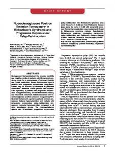
Letter to the Editor PHOTOELECTRON P R O D U C T I O N IN BaF 2 -TMAE DETECTORS P. S C H O T A N U S , C.W.E. V A N E I J K , R.W. H O L L A N D E R and J. P I J P E L I N K Delft University of Technology, Delft, The Netherlands Received 24 February 1987 The wavelength dependence of the photoelectron yield in a BaF2 -TMAE detector was studied. We found that the signal in such a detector stems mainly from an emission of scintillation light at 195 nm. The decay time constant of this component is the same as that of the 220 nm component: (870 ±30) ps.
and spatial distribution of these photoelectrons. Re cently, some new data have become available concern ing the optical absorption in TMAE vapour and its quantum efficiency [7]. In order to calculate the wave length at which the majority of the photoelectrons is produced, we measured the emission spectrum of BaF2 between 170 and 450 nm. A cylindrical BaF2 crystal, 7 mm thick, 30 mm diameter (manufactured by Harshaw) was irradiated with X-rays emitted by an X-ray tube at 30 kV. The scintillation light was analysed by means of a Jobin Yvon monochromator (model UV-10) coupled to an XP2020Q photomultiplier (PM). The space between the
Since the discovery of a fast scintillation component of barium fluoride (BaF 2 ) at 220 nm [1], and of the detection of BaF2 scintillation light in a multiwire pro portional chamber [2], the BaF 2 -proportional counter combination has been applied for the detection of all kinds of particles [3,4] and gamma radiation [5,6]. In such a detector, the scintillation photons are absorbed by the photosensitive gas TMAE. A fraction of these photons is converted into photoelectrons that are de tected in the wire chamber. It is important to know where exactly in the detector the electrons are created, since physical properties of the detector such as the time and position resolution depend on the drift time
300
200
400
wavelength A [nm]
Fig. 1. Emission spectrum of BaF2when irradiated with X-rays from a 30 kV generator and absolute quantum efficiency of TMAE vapour |4|. 0168-9002/87/S03.50 © Elsevier Science Publishers B.V. (North-Holland Physics Publishing Division)
- 58 -
P. Schotanus et ai / Photoeleclronproduction
in BaF,-TMAE
587
detectors
195 nm .0
T= 870 ps
CD
(0
190
210
c .0) 'in c o
230
'S
wavelength A [nm]
£
Fig. 2. Wavelength dependent photoelectron yield in a BaF2TMAE detector; an infinite absorption lengih is assumed.
a 250
300
350
yoo
time (67 ps/channel) crystal and the PM was flushed with nitrogen, which ensured the transmission of the UV light down to 170 nm. The monochromator has a holographic grating and a resolution of 4 nm. Fig. 1 shows the emission spec trum, corrected for the quantum efficiency of the PM and the transmission of the monochromator. Next to the well known 220 and 310 nm components, we ob serve a third component with an emission maximum at 195 nm. Below this 195 nm component, another emis sion with a very small intensity can be seen around 180 nm. The emission components at 195 and 180 nm have also been measured by Valbis et al. [8], but have re mained unnoticed by other authors. From examination of the TMAE quantum efficiency curve, also shown in fig. 1, we learn that the majority of photoelectrons detected in a BaF 2 -TMAE chamber stems from the 195
JQ
to to
c u> 'in c O
'S a
J:
250
300
350
10Q
time (67 ps/ channel) Fig. 3. Time distribution spectrum of the 220 nm component of the scintillation light pulse from BaF2 using an UV mono chromator.
Fig. 4. Decay of the 195 nm scintillation light component of
BaF,. nm emission component. In order to study this effect in more detail, we calculated the product of the BaF2 emission and the TMAE quantum efficiency as a func tion of wavelength. Fig. 2 shows the wavelength depen dent photoelectron yield for an infinite absorption length, i.e. all scintillation photons are absorbed. We clearly see that the distribution peaks at 195 nm, from which we may conclude that in a BaF 2 -TMAE detector the signal mainly stems from the 195 nm (6.3 eV) scintillation component of BaF2. We measured the emission components from BaF2 for a large number of crystals. The intensity ratio of the 195 and 220 nm bands remained constant in all sam ples, independent of the observed variation in the inten sity ratio of the 220 and 310 nm components. This is in agreement with ref. [8], where also it was reported that the intensity of the two bands has the same temperature dependence. Using the TMAE optical absorption data from ref. [7] and the data from fig. 2, we calculated the weighted average for the inverse absorption length at 1 Torr of TMAE vapour pressure: 1.13 c m - 1 . Together with the generally accepted equation for the TMAE vapour pressure as a function of temperature [9], this yields absorption lengths (1/e) at 20, 40 and 50 ° C of respectively 33, 8 and 4 mm. In order to determine the decay times of the emis sion components, a light pulse shape study was per formed by means of the single photon counting tech nique described in ref. [10]. A crystal was coupled to an XP2020Q PM which delivered the start pulse to a time to amplitude converter (TAC). The scintillation photons pass through the monochromator mentioned earlier and are detected by a second photomultiplier which detects only single photons and delivers the stop pulse to the TAC. The crystal was irradiated by gamma rays from a
- 59 -
588
P. Schotanus et al. / Photoelectron production in BaF:, - TMA E detectors
137
Cs source. With the monochromator set at 310 nm, we observe a decay time of (630 ± 30) ns, the same as obtained in refs. [1,11]. Fig. 3 shows the measured decay at 220 nm. A decay time constant of (880 + 30) ps was found, which agrees well with the data in ref. [11], where the same method of measurement was used. At 195 nm, we measured the decay time spectrum shown in fig. 4. The decay time was found to be (870 + 30) ps, within an error which is the same as that of the 220 nm component.
References [1] M. Laval, M. Moszynski, R. Allemand, E. Cormoreche, P. Guinet, R. Odru and J. Vacher, Nucl. Instr. and Meth. 206 (1983) 169. [2] D.F. Anderson, G. Charpak, Ch. von Gagern and S. Majewski, Nucl. Instr. and Meth. 217 (1983) 217.
- 60 -
[3] D.F. Anderson, G. Charpak, W. Kusmierz, P. Pavlopoulos and M. Suffen, Nucl. Instr. and Meth. 228 (1984) 33. [4] C.L. Woody, Technical note No. 120, Physics Depart- ment, Brookhaven National Laboratory, associated Uni versities Inc., Upton, New York 11973 (Sept. 18, 1986). |5] P. Schotanus, C.W.E. Van Eijk, R.W. Hollander and J. Pijpclink, to be published in Proc. IEEE Symp. (Feb. 1987). [6] P. Mine, J.C. Santiard, D. Scigocki, M. Suffcrt and G. Charpak, ibid. [7] R.A. Holroyd, J.A. Preses and C.L. Woody, submitted to the 23rd Int. Conf. on High Energy Physics, Berkeley, CA (July, 1986). [8] Y.A. Valbis, Z.A. Rachko and Y.A. Yansons, JETP Lett. 42 (1985) 172. [9] D.F. Anderson, IEEE Trans. Nucl. Sci. NS-28 (1981). [10] L.M. Böllinger and G.E. Thomas, Rev. Sci. Instr. 32 (1962) 1044. |11] S. Kubota, M. Suzuki, J. Ruan, F. Shiraishi and Y. Takami, Nucl. Instr. and Meth. 242 (1986) 291.
CONTINUATION OF SECTION 4.5 Photoelectron statistics Due to the bad overlap between the TMAE quantum efficiency curve and the BaFp emission spectrum, the number of primary photoelectrons (p.e.) detected per aborbed 511 keV radiation quantum is rather small.Different authors have measured and calculated the photoelectron yield [64,67]. The reported values range from 10 to 20 photoelectrons per MeV which is much smaller than the number obtained with photomultipliers: (450/MeV for the fast component of BaF ; see Table IV, section 3.3). Using an SSPC for the detection of low energy photons (< 1 MeV) does not allow a good energy resolution due to the large statistical error in the number of photoelectrons (cf. eq. 3-5). For 662 keV gamma rays, an energy resolution of 80 % FWHM has been reported [84]. Since the chance to create n primary photoelectrons from N photons is small, the distribution of the number of primary photoelectrons P(n,p) follows a Poisson law: P(n.u) = P j " and
P
(4.7)
I P(n.u) = 1 n=0,»
(4.8)
with u being the average number of photoelectrons created per event. For small values of p (low gamma ray energies in case of an SSPC), P(0,p) which does not give a contribution to the signal, may not be neglected. This means that the efficiency decreases at low gamma energies, which is advantageous for the rejection of low energy scattered radiation. Fig.33shows 1-P(0,u), the intrinsic efficiency, as a function of p. Also 1-P(0,p)-P(l,p) is shown to demonstrate the effect of a threshold. The low number of photoelectrons also affects the other performance characteristics such as time and position resolution of the detector. For high energy particles detected in SSPCs, a time resolution between 0.5 and 1 ns and a position resolution of 1-3 mm have been reported [64,67,85,86].
- 61 -
T~i—i -
i
i
i—i—i—r
l-P(O)
•
-
o
0.8 ■a 0.6 Ö -H
J-« +->
^0.4
1-P(0)-P(1)
CT3
§0.2
J
I I 1 I I 1 L_l
L_J_
2 4 6 8 10 average number of photo electrons p Fig.33- The theoretical intrinsic efficiency of an SSPC as a function of the average number of photoelectrons created per event. For details see text.
Separate absorption gap A set-up of an SSPC is schematically shown in Fig.3^- A grid consisting of closely spaced wires (grid 1) defines an equipotential plane on the BaF_ crystal surface. This is necessary since BaF_ is an insulator. Electrons produced in the absorption region between the grid 1 and 2 are pulled towards the MWPC by a drift field.
grid 1 UV absorption + drift region preamplification
MWPC
final amplification
grid 2 cathode anode cathode
Fig.3^- SSPC configuration with the absorption region separated from the amplification region.
- 62 -
Absorption gap length Since the vapour pressure of TMAE is only 0.3 Torr at room temperature (20 C), causing an (1/e) absorption length of almost 3 cm, a large gap would be required for efficient UV absorption. This results in unacceptably long photoelectron drift times and a large lateral diffusion of the electron cloud. It is therefore desirable to increase the TMAE vapour pressure by heating the detector system (see Table V).
Multi-step operation If the field between the second grid and the cathode is large enough to start gas amplification, the detector works in the earlier defined multi-step mode. Directly behind the cathode, the field becomes smaller and a significant part of the electrons is lost. The surviving fraction drifts towards the anode and is subjected to a second amplification step. This way of operation ensures a small drift time between grid 2 and the anode (see Fig.3*0- All photo electrons created within the absorption region are in principle subjected to the same gas amplification, and the optimum energy resolution can be studied. However, the drift time within the absorption gap limits the time resolution and the performance at high count rates.
Operation without separate gap An alternative is the configuration depicted in Fig.35- In this case, the amplification process immediately starts below the crystal. The majority of the photoelectrons is created between the grid covering the scintillator surface and the first cathode. Only photoelectrons created close to the crystal undergo the full first step amplification process. This means that the pulse height depends on the place of absorption in the gap. Multi-step operation with this configuration yields narrow pulses which allows high count rates.
barium fluoride crystal grid UV absorption + preamplification
__ ,,,,_-
_ _ _ _ _ final amplification
MWPC _ _ _ _ _ _ _
—
cathode ,
anode — cathode
Fig.35. SSPC configuration without separate absorption region.
- 63 -
4.6 THE SSPC AS A GAMMA CAMERA FOR PET In chapter 3 we illustrated that one of the needs in positron emission tomography is the improvement of the spatial resolution to the theoretical limits of 2-3 mm. This has lead to the development of complicated ring systems containing thousands of scintillation crystals and photomultipliers. In order to decrease the complexity and cost of these systems, multi-crystal readout systems with e.g. position sensitive photomultipliers are being developed. To minimize the scatter fraction, the application of PM tubes is connected to the concept of ring-type PET scanners which subtend a small solid angle. This brings us to the second need in PET: an increased sensitivity, which can only be attained by constructing devices subtending a larger solid angle of detection than that in ring systems. Thirdly, the present PET cameras suffer from serious dead time losses at count rates of the order of 10 per second caused by the rather long decay time of the scintillators. A gamma camera that does not have this problem would be desirable. Thus, the ideal PET camera has a good position- and time resolution, small dead time, high efficiency and is insensitive to scattered radiation. BaF_ is a high Z scintillator with a high absorption efficiency for 511 keV annihilation radiation and a relatively high photo fraction. Since in an SSPC only the fast scintillation component is detected, dead time losses caused by the scintillator can be neglected. On the other hand, the application of low pressure MWPCs enables a good time resolution and high count rates. In principle, the SSPC is an uncomplicated (inexpensive) detector for the position sensitive detection of annihilation radiation. Also, a certain insensitivity to scattered radiation is present. In this study, a number of important properties of SSPCs for the position sensitive detection of annihilation radiation will be investigated. For that purpose we have built a detector which will be described in detail in chapter 5 together with the results. Also, possible ways of implementation of such a detector in a PET system will be presented.
- 64 -
5 DETECTION OF 511 KEV ANNIHILATION RADIATION WITH A SOLID SCINTILLATOR PROPORTIONAL COUNTER: EXPERIMENTS AND RESULTS This chapter describes experiments to investigate important parameters for the detection of 5 H keV annihilation radiation with an SSPC. The efficiency for ultraviolet light detection in a wire chamber has been measured. Also, the possibility to detect scintillation light in a liquid TMAE photocathode has been investigated. The first experiments have been 2 performed with a small test detector (10 x 10 cm ); later a larger 2 detector (18 x 18 cm ) has been constructed. The final detector, consisting of several wire chambers and two large barium fluoride crystals, is described in detail in section 5-6; important parameters of its performance are presented in the succeeding sections.
5.1 EXPERIMENTAL PROCEDURES AND METHODS
5.1.1
The multiwire chamber
The general principles of a wire chamber and its configuration (anode/cathode planes) have already been presented in chapter k. For our purpose we use wire chambers with cathodes consisting of wire planes which enables us to deduce position information from the cathode signals. The position of the wire planes with respect to the scintillation crystal can be different since in an SSPC several modes of operation are possible (see Fig-3*+, 35), but the distance between anode and cathode planes is k mm in all experiments. All wire frames are made of printed circuit board epoxy-glass (G-10) which is a material well suited for the purpose although some outgassing occurred in practice (see section 5-6.2). Cathode planes consist of 50 um Cu/Be wires at a pitch of 2 mm. The anode planes consist alternately of anode wires (Au plated W, 20 um diameter) and a 50 um cathode wire at 4 mm distance, thus creating a cell structure (see Fig.36). By introducing cathode wires in the anode plane, an almost radial field is obtained up to several mm away from the anode. This results in a relatively large gas amplification at low anode potentials. A computer program, which numerically calculates a solution of the
- 65 -
o o o o o o o o o
cathode p l a n e
0
anode
*
0
*
0
o o o o o o o o o 2 mm
plane
cathode p l a n e
o=50 urn diameter (cathode wires) •=20 um diameter (anode wires)
Fig.36. Schematic of the anode cell structure
Laplace problem in two dimensions, has been used to calculate the field lines in the MWPC. The smallest iteration step must be of the order of the anode wire radius and was chosen 10 um. The calculation has been performed for the MWPC configuration shown in Fig.35- The distance between grid and cathode was 2.5 mm; the grid at the crystal was assumed to define an equipotential plane. The potential difference between anode and cathode was the same as between cathode and grid (330 V): a typical operation condition. Fig.37 shows the resulting equipotential lines in a part of the detector. Between grid and cathode, the field is constant over a large depth so that this part of the detector may be considered as a PPAC. Directly behind the cathodes, the fieldstrength decreases. This implies that only part of the electrons produced in the first amplification step is transmitted. For a wire grid with wire diameter D and pitch S the electron transmission through the grid equals the ratio of the field strengths at both sides (E and R ) if:
E ^ < - & =
T
with p = TTD/S
This equation is derived in ref.[87]- If E /E, > 1/T, the transmission ,-j
a
D
is 100 %; In our case, p=7.85.10~ which means that for E /E < O.85 a D the transmission is the ratio of the field strengths E and E, . a b As can be seen from Fig.37. the field is not homogeneous and the transmission through the cathode is position dependent. However, since the gas amplification process includes several cells, the transmission inhomogeneity is not important in practice.
- 66 -
crystal
i;;': '•
grid
'".-;;i;l-."-
'']-\]l:]-'.'■■...■■''.
anode plane
*
■■■■■.,::\\i\].'
..
cathode plane
...::!:t!i::...
■. ! ■!iti|: : ..•■''
cathode plane
Fig.37- Calculated equipotential lines (50 V interval) for the cell anode structure in combination with a PPAC.
The calculation described above is a simplification of the reality since in the detector the wires in the anode plane are perpendicular to those in one of the cathode planes. A full three dimensional calculation of the real potential distribution lays unfortunately beyond our computing capabilities. It is unlikely, however, that the depth of the constant field region between grid and cathode and the radial field region around the anode are significantly different in the two situations.
- 67 -
Also, the gas amplification factor at the edges of the MWPC has been investigated. When no counter measures are taken, the field strength increases at the edges of an MWPC if the anode plane suddenly ends. Normally, thick (50-100 um) anode wires are used to terminate the field in a proper way. From calculations of the field it was concluded that ending the anode plane with a normal 20 pm thick anode wire (and not a cathode wire), provides an adequate termination of the field.
5.1.2
Position readout
A number of different techniques exist for locating the center of the induced charge distribution on the cathode wires of an MWPC. The most straigthforward way is to determine the center of gravity of the charge distribution on the cathode plane. For this purpose, cathode wires are often connected in groups (see Fig.38) each group being connected to its own amplifier. After digitalisation, the distribution is determined and the maximum is calculated. Since at low pressure operation, the distribution includes several wire groups, interpolation is possible and the position resolution is not limited by the group size. The disadvantage of the method is that a large number of amplifiers and ADCs (Analog-to-Digital Converters) is required. A reduction in the number of amplifiers can be obtained by combining wire groups and using an encoding principle [88].
Fig.38. Schematic of an MWPC with cathode wires connected in groups for two-dimensional position readout.
Another way to determine the center of gravity of the cathode charge
- 68 -
h R,
R
R
-,-
R^
cathode wire groups
Qi
U,
u,
Fig.39- Principle of charge division; the charge injected at point x is distributed over the impedances Z. and Z ? . For other symbols see text.
distribution is to connect all the wires (or groups of them) with resistors and to measure the charge at both ends of the resistor chain (Fig.39)- The sum of the total resistance of the chain is usually chosen a few hundred kO to obtain a maximum signal-to-noise ratio and an acceptable pulse rise time. The charge induced per event on the cathodes (Qn) will be distributed over the chain and a charge of respectively Q1 and Q_ is delivered to the input of charge amplifiers at both ends. In the ideal case with no charge losses we can write:
(5-2)
VZ2 and
(5-3)
z1+z2
When the two amplifiers are identical, the relative position' of the charge injection in the resistor chain can be deducted from the two amplifier signals IL and Up:
(5-4)
u1+u2
In the case of an induced charge distribution, x is the point of gravity of the distribution. The normalisation on the total amount of charge delivered per event and the calculation of x can be performed on line using two charge sensitive amplifiers and two ADCs. A disadvantage of the method is that due to the finite input impedance of the amplifiers, a non-linearity is present at the edges of the chain. It can be reduced by adding a relatively large
- 69 -
resistor R , with a value of roughly 20 % of the total resistance of the chain, between the last wire(group) and the amplifier. Due to dispersion in the resistor chain, a time lag of the order of microseconds appears between signals not detected in the middle of the chain. An alternative way is to use an externally connected delay line. The induced cathode signal is (capacitively) coupled into the delay line equipped with fast charge amplifiers at the ends. From the difference in arrival times between the pulses from the amplifiers, the position of an event can be calculated (see e.g. [89,90] and Fig.17). Delay line readout limits the maximum count rate by the travel time of the pulses over the line (a few nanoseconds per mm). The determination of arrival times is often accomplished using constant fraction timing. A third readout method is the wedge and strip approach. Here, the two dimensional charge distribution on a cathode plane is measured. One cathode plane in a wire chamber is replaced by a plane consisting of conducting wedges (W) and (Z) and strips (S), separated by insulating material (Fig.40). From the charges induced on the wedges and the strips, and from the totally collected charge, the two dimensional position of an avalanche in an MWPC can be calculated [91]- The method can only be applied if no (UV) light or electron transmission through the readout plane is required. An advantage is that for two-dimensional readout, only three amplifiers are needed. Wedge and strip readout is not widely used at the moment but is gaining attention.
2Qc Fig.40. Schematic diagram of the 3-electrode wedge and strip anode
Y=
with its position algorithm [91].
2QW
All methods mentioned above require some trigger that determines the moment at which cathode signals must be collected and digitized. Often the anode signal is used for this purpose.
- 70 -
For the MWPCs described in this work, we used resistive charge division for position readout because of the simplicity of the method and because all electronic components were readily available. The first experimental MWPC 2 (10 x 10 cm ) had cathode wires (at 2 mm distance) coupled together in groups of four, with resistors of 22 kO between the groups and resistors of 33 kfi between the last group and the charge amplifiers. The MWPCs built later (18 x 18 cm ) have their cathode wires coupled in groups of two with 5.6 kO between the groups (i.e. 4 mm per group) and 10 kO at the ends of the resistor chain. Initially, the cathode wires in one cathode plane of the MWPCs were parallel to the anode wires. In general, however, this presents some problems. In the case of localized showers such as produced by e.g. X-rays (detector filled with atmospheric pressure P-10), the maximum of the induced charge distribution will always lie at the position of an anode wire. This limits the position resolution to half the distance between the anode wires. When the MWPC is used at low pressure in the multi-step mode to detect scintillation light, this effect does not occur because of the extent of the shower. Yet, in the latter case, however, we have noticed a change in position calibration. Therefore, in the final detector, all cathode wires are mounted perpendicular to the anode wires which solved the problem. Two dimensional position readout is obtained by the use of MWPCs on both sides of a scintillation crystal with mutually perpendicular anode wires.
5.1.3
Choice of detector materials
In a photosensitive multiwire detector, the gas mixture should not contain any electronegative compounds which could absorb photoelectrons. The first source of contamination is the TMAE vapour itself which can contain one or more of its oxydation products, some of which are electronegative [92]. To avoid oxidation of TMAE, it should be handled under a nitrogen atmosphere. Furthermore, certain organic compounds (especially plastics) react with TMAE and so "poison" the gas mixture. Some of them partially disintegrate. Examples of not suitable materials are neoprene rubbers and perspex. Teflon, PVC, polyethylene and G-10, however, are well suited for a TMAE environment. A material excellent for 0-rings is Viton. Next to several metals such as aluminium and stainless steel, we have used Teflon, Kapton, PVC and G-10 for
- 71 -
over two years in the detector system without any problems. When choosing other construction materials (for frames, glues, O-rings etc.) one should consult the compendium of outgassing data [93] and the recently published results of compatibility of different materials with TMAE [92].
5.1.4
Electronics
All anode wires in the MWPCs are interconnected. The anode signal is fed into either a Lecroy TRA 510 low noise charge sensitive preamplifier for energy and position studies, or into a Lecroy TRA 401 fast current preamplifier for timing purposes. The charge sensitive amplifier integrates the signal and delivers pulses with a length of about 50 us. In the following we will call this signal the "slow anode signal". The fast current amplifier signal has an intrinsic rise time of 4 ns and is subsequently fed into a Timing Filter Amplifier (TFA) (Ortec, model 454) and a Constant Fraction Discriminator (Ortec, model 934) which delivers logic timing pulses. The slow anode signal is further processed by a spectroscopie amplifier (Canberra, model 1413) before the pulse height can be determined with an ADC (Northern, model NS 623). Later, the TRA 401 has been replaced by a TRA 510 operating in current mode. This turned out to result in a better signal-to-noise ratio. The cathode signals from both sides of the resistor chains are first fed into hybrid charge sensitive preamplifiers (design TU Delft) and then shaped with spectroscopie amplifiers using an integration time of 8 us. Position spectra are determined as follows. The shaped anode signal at the output of the spectroscopie amplifier is fed into a "window unit" which selects pulses within a certain pulse height interval and converts these into logic gate pulses which are delayed and stretched to produce a gating signal for the position ADCs. Fig.4l illustrates the above. Because of the large time dispersion of signals in the resistor chains (maximum value about 20 us), the gate pulse must have a length of 30 us since signals from both ends of the resistor chain must be processed coincidently. For two dimensional position readout, four ADC's are required. The ADC signals are processed by a CAMAC interface, connected to a PDP 11-44 computer, using Direct Memory Access (DMA), Position spectra are constructed by means of a computer program (POSIN) that calculates the
- 12 -
PULSE HEIGHT SPECTRUM
ADC
ANODE . WIRES
DtL t>
SPECTR. AMPL.
PULSE HEIGHT SELECTION
GA' SIG
TRA 5 1 0
{>
CATHODE WIRES
tf
SPECTR. AMPL.
ADC
k 1
r— SPECTR. AMPL.
POSIN UNIT (CAMAC)
PDP 11-44
♦ POSITION SPECTRUM
Fig.4l. Schematics of the wire chamber electronics for determination of position and pulse height spectra. position of an event with equation (5-4) using the four coincident ADC signals. As a consequence of the relatively slow electronics and the way of computer interfacing, the above described way of position determination allows only count rates up to 10 per second.
5.1.5
Gas system, TMAE supply
To fill the detector with the photosensitive vapour and, if required, with a suitable counting gas, a "gas system" as shown schematically in Fig.42, has been contructed. The detector itself is connected by means of valves 1 and 2 to the gas system. With the vacuum connections a and b, the detector can be separated from the gas system for maintainance. All valves (Nupro SS-4H-TW) and pipes are made from stainless steel. A vacuum pump (Balzers DUO 004) and a cold trap filled with liquid nitrogen are used to evacuate the detector down to 4.10
Torr before
putting it into operation. The detector can be bypassed by means of valve 5For experiments with TMAE vapour at high temperatures, all valves and piping can be heated with heating belts. The TMAE reservoir (bubbler type) consists of a glass vesssel with metal flanges and is kept at a certain temperature, with an accuracy of +_ 2
C,
by means of a thermostatic water bath. The gas system is designed such that a continuous flow of counting gas can be led through the TMAE bubbler and the detector. The TMAE reservoir can be separated from the gas system by
- 73 -
11 vacuum pump
trt*h®
cold trap
M
^^t^HH^
M^F^^D^^B^
counting gas
Fig.42
The gas handling system:
1-11=valves, a-d=vacuum connections, M=servo valve, V=needle valve, PI and P2 are pressure meters; for more details see text.
TMAE reservoir
means of vacuum connections c and d. The pressure is regulated by means of an electromagnetic valve M (Balzers RME-010) , controlled by a valve control unit (Balzers, RVG-40), and is monitored by the pressure meters PI and P2, respectively a Pirani element for pressures below 1 Torr and a membrane pressure meter P2 (design Dr. W.C. Heerens, TU Delft) for pressures between 1 and 10 Torr. The accuracy of P2 is 0.05 Torr. By means of the needle valve V, the gas leaves the system.
The detector vessel consists of an aluminium cylindrical box with a lid on top sealed with a Viton 0-ring. Several aluminium rings, 45 mm high can be inserted to increase the height of the vessel. The bottom plane is provided with gas ports and with electrical connections that consist of aluminium oxide (A1_0..) sheets with conducting strips (42 per connector). The sheets are glued into the bottom plane. A water cooled surface 2 (10 x 10 cm ) mounted just above the bottom, provides the possibility to condense TMAE vapour for experiments with liquid layers. The whole vessel
- 74 -
Fig.43
The gas supply system together with the detector.
can be heated with external heating belts. Fig.43 shows the gas system together with the detector. TMAE is used as delivered by the supplier (RSA Corp., NY, USA). The liquid is handled under a nitrogen atmosphere in a glove box to avoid contamination. We have tried to purify TMAE by washing with destilled, deoxygenated water according to ref.[78]. This procedure slightly reduced the intensity of the yellow-greenish colour of the liquid. We neither observed an improvement of the detector performance nor an improvement of the ageing characteristics. The purification procedure was therefore not adopted for standard measurements.
5-1.6
Measuring procedures, tests of the MWPC
Initially, only experiments with TMAE at room temperature (20 C) were performed. At that time, the temperature controlled water bath of the TMAE reservoir was not operational yet. For experiments with liquid layers
- 75 -
of TMAE, the surface at the bottom of the detector was cooled with an external flow of cooling water. TMAE is let into the evacuated detector by connecting it to the reservoir. The pressure in the vessel then equals the saturated vapour pressure at the temperature of the cold surface. By keeping the connection between reservoir and vessel open for a few minutes, TMAE liquid is condensed on the cold surface. Later it became clear that the optimum performance of a BaF2-TMAE SSPC is reached when using TMAE vapour at an elevated temperature. The maximum TMAE temperature attainable in our detector system is 55 C. This is limited by the temperature of cold spots in the detector vessel (e.g. electronic throughputs). The gas filling procedure is as follows. TMAE vapour is first let into the evacuated chamber by opening the valve on the TMAE container. This valve is left open until the pressure, monitored with pressure meter P2, does not increase anymore (usually after about 5 min.) For operation at low TMAE temperatures (< 45 C), a few Torr of isobutane is added to increase the gain. Finally, all valves are closed and the detector is ready for operation. Due to outgassing of chamber components, the pulse height decreases slowly in time. During the first 24 hours this hardly affects the detector's performance; later the maximum obtainable gain decreases. In section 5-6.2, the signal deterioration rates are presented.
All wire chambers have been tested at atmospheric pressure with P-10 (90 % Argon, 10 % methane) counter gas in order to measure the pulse height variation as a function of position. The chambers were irradiated with a 55 Fe source emitting 5.9 keV X-ray radiation. The cathodes were kept at 4 ground potential. The maximum possible gas amplification is 3-10 (V , =1500 V) with less than 10 % variation over the surface of the MWPC. anode The energy resolution at 5-9 keV is 18.5 % at the above mentioned gain. The position resolution induced by noise in the cathode readout system was determined by delivering test pulses to the resistor chain. Fig.44 shows the resulting position resolution as a function of the charge delivered in the middle of the network. For position measurements, only pulses with an noise contribution smaller than 1 mm were accepted.
- 76 -
Fig.44. The electronic contribution to the position resolution as a function of the charge delivered in the middle of the resistor chain.
0.2
0.3 0.4 0.5 0.6
0.7
Q(test) [pC]
5.2 EXPERIMENTS WITH LIQUID TMAE In this section, experiments to study the detection of ultraviolet light in a wire chamber are described. The detection efficiency has been measured as a function of wavelength for TMAE vapour as well as for a layer of liquid TMAE. Also, the influence of a liquid layer of TMAE on the signal detected from a barium fluoride scintillator has been investigated. Part of the results was already published in ref.[94]. 5.2.1 Design of the test detector The MWPC is mounted in the detector vessel with a distance of 7 mm between the lowest cathode plane and the cooling surface. The lid of the vessel is situated 9 mm above the upper cathode (see Fig.45). All conducting surfaces including the cooling surface are kept at earth potential. A small pinhole in the lid with a quartz window is used to irradiate the detector with ultra violet light from a xenon flash tube (EG&G, model FX265 UV) in combination with a monochromator (Oriel, model 7240, resolution 5 nm). A 30 mm diameter, 8 mm thick barium fluoride crystal (Harshaw) was mounted in the lid. The distance between the crystal surface and the upper cathode is 9 mm. The detector is filled with TMAE vapour at 20 °C and a few Torr of
- 77 -
pinhole + quartz window Fig.45. Wire chamber
BaFi
configuration for experiments with
9 mm 0
B
o
0
0
0
•
0
o
liquid TMAE layers.
o o o o o o o o o o •
o
•
o
cathode plane o anode plane cathode plane
7 cold surface
isobutane. For the study of liquid layers of TMAE, the detector is connected to the TMAE reservoir at 20 is kept at 10
C while the temperature of the cold surface
C: TMAE condenses on the surface and after about ten
minutes, the valve on the TMAE reservoir is closed. Then a few Torr of isobutane is added. In all experiments, the signal from the anode wires (all coupled together) is measured.
5.2.2
UV detection in TMAE
Efficiency curves as a function of wavelength have been determined by dividing the signal from the MWPC by the emission spectrum of the xenon flash tube measured with a photomultiplier (XP2020Q). To our regret, it was not possible with our experimental set-up to measure the absolute quantum efficiency. The detector can be operated in different modes. In case of a positive potential on the cathodes, multi-step amplification becomes possible and photoelectrons created close to (and at) the cold surface and the lid contribute most to the signal. For very low cathode potentials, not large enough to start gas amplification in regions A and C (see Fig.45).photoelectrons created in the entire regions A and C contribute to the signal. Curve a in Fig.46 shows the relative quantum efficiency measured with all
- 78 -
"l
10
*
Holroyd et al.
+
460/10 V
•
460/10 V with cooling
I
:
i
1
1
1
*
460/320 V
x
460/320 V with cooling
g 100
P = 2 Torr. P = 2 Torr.
T3
10
&*
b \ i
200
i
i
i
210 220 230 240 250 wavelength [nm]
i
260
200
210 220 230 240 250 wavelength [nm]
260
Fig.46. TMAE quantum efficiency as a
Fig.47- UV detection efficiency as a
function of wavelength at low cathode
function of wavelength at high cathode
potentials; a: no cooling, b: Holroyd
potentials; a:without cooling, b: with
et al. [77]"> c: with cooling.
cooling.
the surfaces in the chamber at 20
C. The anode is kept at 460 V, the
cathode at 10 V and the total pressure is 2 Torr. The vapour pressure of TMAE is 0.3 Torr so that approximately 50 % of the light with a wavelength between 200 and 250 nm is absorbed along the 24 mm long absorption path (cf. Fig.26). In all situations we could measure a signal above 230 nm; this can only be explained by the presence of a thin adsorbed film of TMAE on surfaces in the detector. As a comparison, curve b shows the absolute quantum efficiency in TMAE vapour obtained by Holroyd et al. [773- Curve a is normalized on Holroyd's value at 200 nm. The surface effect increases the quantum efficiency above 210 nm. To measure the influence of a liquid photocathode, TMAE was condensed on the cold surface. The vapour pressure of TMAE is then 0.14 Torr which results in an absorption of approx. 30 % of the photons (200-250 nm) in the
- 79 -
gas. The anode and cathode voltages and the total pressure were the same as in the previous case. Curve c in Fig.46 shows the measured efficiency. Curves a and c may be compared absolutely. With cooling, the efficiency below 230 nm is significantly smaller than without, due to a decrease of the contribution from the vapour phase. To investigate the influence of a high field between surfaces and cathodes for efficient extraction of photoelectrons from the surfaces, the cathode wires were put at the maximum possible voltage of 320 V. The temperature of the TMAE vapour and of the detector was 20 C. With the anodes at 460 V, the efficiency shown in Fig.47 (curve a) was measured. Again, the efficiency curve does not represent the absolute quantum efficiency. Due to a more efficient extraction of photoelectrons from the surface film, compared to the case without a high field, the relative contribution from the surface has increased. The maximum detectable wavelength is 260 nm, which is smaller than the theoretical value of 330 nm [78]. Next, the efficiency was measured for TMAE vapour at 10 C and a liquid layer of TMAE condensed on the surface. All potentials and the total pressure were the same as in the previous case. Fig.47 (curve b) shows the resulting efficiency; compared to the situation without cooling, the efficiency has increased above 210 nm. It is not possible to compare the efficiency curves from the Figs.46 and 47 absolutely since, as mentioned, the curves do not represent the absolute quantum efficiency, and the gas amplification is different in both cases and cannot be calculated. Fig.48 shows the xenon flash tube signal at 220 and 230 nm as a function of the cathode potential. The potential difference between anode and cathode is 600 V and the total pressure is 7-5 Torr. Without cooling (Fig.48a), the curves show the same behaviour: a gradual increase in signal due to an increasing collection of photoelectrons followed by a larger increase due to amplification towards the cathode starting around 120 V. Fig.48b shows exactly the same situation in presence of a liquid layer of TMAE. This results in a strong increase in the 230 nm signal at high cathode potentials. The smaller TMAE concentration in the gas results in a small decrease of the efficiency at 220 nm.
The 'liquid layer results' are in good agreement with those obtained by Peskov et al. [63] who have also reported an improvent in the quantum efficiency in presence of a liquid layer of TMAE for wavelengths larger than
- 80 -
231 nm (an.-cath.) "
120
DUU
220 nm
(an.-cath.i
P = 7.5 Torr.
= DUU v
P = 7.5 Torr. 220 nm
without cooling 231 nm
20
20 -
100 V(cathode) [ V ]
V(cathode) [ V
Fig.48. Intensity of the signal produced by a xenon flash light, as a function of the potential on the cathode; a: without cooling, b: with cooling.
220 nm. The highest efficiency is obtained when a strong electron extraction field is applied. The absolute efficiency for electron extraction from liquids depends also on the type of counting gas used. The improvement of the UV detection efficiency in MWPCs by using liquid photocathodes is not as high as theoretically expected, because the electrons do not easily escape from the liquid. By choosing other solvents for TMAE, with a larger electron mobility and a larger electron thermalisation length, the chance that electrons can escape from the liquid is slightly improved (see section 4.3).
5-2.3
Scintillation light detection with liquid TMAE layers
The signal from the barium fluoride scintillator (irradiated with a !37.
Cs gamma source) was examined with- and without a liquid TMAE layer on
- 81 -
the cold surface (10 C ) . No significant change in the signal was observed. The improvement in photoelectron yield measured for xenon light does not show up in the case of the scintillator. This can be explained by the fact that the xenon light is emitted in a narrow beam, a large fraction of which reaches the liquid layer on the cold surface. The scintillation light, however, is emitted over a wide angle and is consequently detected mainly in the gas. The decrease of the contribution from the gas is then roughly compensated for by an increase of the contribution from the liquid. Furthermore, only for wavelengths larger than 220 nm an improvent in quantum efficiency has been measured. From the product of the barium fluoride emission spectrum and the liquid TMAE quantum efficiency, the expected improvement in photoelectron yield can be calculated. Using the highest reported efficiency values [63], an improvent of 6% for pure TMAE and 12 % for TMS + TMAE (methane counting gas) results. With isobutane as counting gas, the effect is reported to be only half as large [63]. It can be concluded that the use of liquid photocathodes described above, will not be of any advantage for the operation of SSPCs. Therefore the idea of a liquid layer was abandonned.
5.3 DETECTION OF ANNIHILATION RADIATION IN AN SSPC, RESULTS AT 20 °C This section describes experiments with an SSPC operating at a temperature of 20
C. Combination of different barium fluoride crystals 2 with an 18 x 18 cm MWPC have been tested. Part of the results have been published in ref.[95]The MWPC is described in 5.1.1; in one cathode plane, the cathode wires are coupled in groups of two and the wires in the two cathode planes are perpendicular to each other to enable two-dimensional position readout (see Fig.49). Several BaF? crystals could be mounted at various distances above the MWPC. All crystals were mounted with 100 um thick teflon tape on the side opposite the light window, which provides good (diffuse) reflection of the UV scintillation light [95]. Scintillation photons leaving the crystal enter the absorption gap where they can ionize TMAE molecules (see Fig.50) In this region, a well defined field drifts the photoelectrons into the MWPC. This field is accomplished by a wire mesh with an optical transmission of 81 % (stainless steel, 50 um wire diameter, 0.5 mm pitch), situated directly below
- 82 -
Fig.^9. View of the detector with the top (containing the BaF
crystal) removed.
the crystal surface, and a wire grid- consisting of 50 um diameter Cu/Be wires at a pitch of 2 mm separating the absorption and amplification regions. For timing experiments, the crystal was mounted directly above the upper cathode. This decreases the electron drift times. UV photons leaving the BaF_ crystal have a certain probability to be absorbed by the TMAE vapour and subsequently produce photoelectrons. This chance depends on the TMAE vapour density along the optical path and the quantum efficiency for photoelectron creation. In e.g. 30 mm TMAE vapour at 20
C, 70 % of the scintillation photons is absorbed (cf. Table V ) .
BARIUM FLUORIDE CRYSTAL WIRE MESH
ABSORPTION REGION SEPARATION GRID CATHODE 0
-
0
-
0
-
0
-
0
-
ANODE
CATHODE
Fig.50. Schematic drawing of the detector. UV absorption region variable, anode-cathode distance 4 mm.
- 83 -
5-3.1
Energy and time resolution studies
For energy resolution studies, we used a 150 mm diameter 8 mm thick BaF_ crystal (Merck) and an. absorption gap of 30 mm. The separation grid was positioned 4 mm above the upper cathode and a potential of 50 V was applied to it to define the drift field between the crystal and the MWPC. The anode voltage was 420 V and the cathode voltage was 100 V. Figs.51a and b show the energy spectra of
Co,
Cs and
Na. The gamma energies of the
nuclides are 1170 and 1330 keV for Co, 662 keV for 137 Cs and 511 and 22 1275 keV for Na. The energy resolution of the SSPC is poor due to the small number (about ten) of photoelectrons. In spite of this, the 22 contributions from the two Na-lines can be observed in the spectrum. The unusual shape of these spectra results from overlap of the photopeak and the Compton distribution, at an energy resolution of about 100 %. One should realize that in an 8 mm BaF- crystal, only 20 % of the absorbed 5 H keV gamma radiation contributes to the photopeak. Adding a few Torr of isobutane to the counting gas, did not significantly change the shape of the energy spectrum. For time resolution studies, the BaF- crystal was mounted directly above the upper cathode at a distance of 0.5 mm. To obtain the maximum gas amplification, the chamber was operated in multi-step mode with 800 V and 400 V applied on the anodes and the cathodes respectively. This means that the active absorption volume is very small (only electrons generated in a thin layer close to the cathode contribute to the signal) causing a loss in sensitivity. However, a gain in timing performance results, since the photo electrons originate from a thin layer close to the cathode. The detector was filled with TMAE vapour and isobutane to a total pressure of 5 Torr. The coincidence time resolution for 511 keV annihilation radiation was measured using a Pilot-U (fast) plastic scintillator (40 mm diameter, 10 mm thick) coupled to an XP2020 photomultiplier as a "start 22 detector", whereas the SSPC delivered the "stop pulse". A small Na point source provided the 511 keV annihilation radiation. The threshold on the photomultiplier was set at 50 % of the 5 H keV Compton edge. The resulting time resolution varied between 3 smd 10 ns depending on the threshold set on the SSPC signal. This large spread is caused by the large variation in photoelectron drift times associated with operation at low TMAE temperatures. In the section 5-4 we will report in more detail on the time resolution of the SSPC.
- 84 -
100
203
300
400
500
600
700
S00
900
10
900
1000
pulse height (arb. units) 100
s
300
200
400
500
600
700
800
b
13-
s 7 12-
22
Na
11 -
-
0-
■33 »: a8
g"
511 keV
Ö *1 o. cn
•s *g 3-
1275 keV
O
2 -
-.
1
.
r ■" ~ i
'■ ' ' \ '
1 -
pulse height (arb. units)
0-
Fig.51. a:
Co and
absorption gap. b:
„„ „ ,. „„ _ with a 30 mm -5'Cs energy spectra at _„ 20 C Na energy spectrum at 20 °C with a
30 mm absorption gap; the contribution of the two energies (511 keV and 1275 keV) to the spectrum are indicated. 5-3-2
Position determination at 20 C
The position sensitivity of the detector was measured for an absorption gap (distance between crystal and separation grid) of 30 mm. The position readout system is triggered by the anode signal on which a threshold is set to reject small pulses from the cathode resistor chains. The threshold was
- 85 -
chosen such that the electronic contribution, caused by the noise from the resistor chains, was less than 1 mm (see Fig.44). The chamber was filled with TMAE vapour and we added 3-6 Torr of isobutane to increase the pressure to achieve a higher gas amplification: at 0.43 Torr, the maximum gas amplification (before discharge) is about an order of magnitude smaller than at 4 Torr. The anode and cathode potentials were maintained at a potential of 800 V and 400 V respectively. The separation grid was kept at a potential of 50 V. First the position spectra from some small BaF_ crystals were measured. A 13 mm diameter, 8 mm thick crystal (Harshaw) and two 8 mm diameter, 5 m m thick crystals obtained from Dr. H.W. Den Hartog, Solid State Physics Laboratory, University of Groningen, were used for this purpose. Irradiation of the largest crystal, 13 mm in diameter, with a small
Co
point source resulted in the position peak shown in Fig.52. The results obtained with some other gamma sources are presented in Table VI; the error represents the variation observed from different measurements. The position peak width increases with decreasing gamma-ray energy since the number of photoelectrons produced per absorption event is smaller. For the smaller crystals with a diameter of 8 mm, the same values were found. This means that the width of the position peak at 20
C is mainly
determined by the lateral spread of UV light in the gas.
200
200
300
500
«e
600
700
800
900
1080
13 mm diam. BaF,crystal 150
■% 150
12 mm FWHM
CD
o
200
300
40B
800
500
900
10
position [ 58 ch/cm ] Fig.52. Position spectrum of a 13 mm BaF_ crystal irradiated with a
- 86 -
Co source.
Table VI. Position peak width obtained from a 13 mm diameter BaF_ crystal for different gamma energies at 20 C. Nuclide 60„ Co 22
Energy (keV)
Peak width (mm) 12 +_ 1
1170,1330 511,1275
Na
^Cs
15 "
662
5?Co
16 "
122,136
21 t 2
Fig.53 shows a two dimensional scatterplot of the two 8 mm crystals, mounted next to each other at a distance of 30 mm. The non-linearity in the cm scale is caused by the resistor chain readout system. Compton scattering and spread of the scintillation light within the scintillator also contribute to the position resolution. These contributions play an important role in larger crystals. The determination of the position resolution for large scintillators with gamma-ray sources is complicated by the collimation problem. To study the resolution at the 150 mm diameter 90 Sr beta source. The signal
crystal, it was irradiated with a collimated
measured with the MWPC was of the same order of magnitude as when the
t w o BaF 2 c r y s t a l s
60 ■ 01 0150 -
■b CO -
«0 -
TO-
O
-
30 -
::
iiiliii
■ ^^W&i^MB ■' 'B^^yffPfyUk
u20 -
10-
01 — 0 — ^4 —
> i i i 76 5 4
1 3
1 2
1 1
1 0
1 1
2
3
4
5 6 7
[
CI
" ]
6fl
Fig.53- Scatterplot showing the image of two small 22 8 mm diam. BaF_ crystals irradiated with a Na source, FWHM = 15 mm.
- 87 -
Co
150 x8jra_BaF2 crystal
60 -*i -
^ ^
0 1 0 1 -
50 -
A
-
^ \
i :
1 -3?* - 4
ro-
v
90
Sr
N.^ i \
/'JÉÉp*
u40 -
- r j
\
v^* * ,
\
o30ro20 ■ u *■01-
10 -
01 — -J —
11 11 76 5 4
3 2
1 0
1 2 3 4 5 6 7
l U" J
Fig.54. Image obtained by irradiating the 150 mm 90 diam. BaF_ crystal with a collimated Sr source.
source was used. The width of the beam was 1 mm. Fig.54 shows the resulting "image"; the solid circle represents the crystal boundary. The FWHM of the peak is 19 mm. The peak is broader than in the case of small crystals because of the larger lateral spread of scintillation light within the crystal and in the gas. From the above measurements we can conclude that at a TMAE temperature of 20 C, the position resolution is about 2 cm. Clearly, a decrease of the effective absorption length (a higher TMAE vapour pressure) is desirable. This will also improve the time resolution.
5.4
EXPERIMENTS AT ELEVATED TEMPERATURES In this section we discuss the operation of the SSPC at elevated
temperatures. In a separate paper (see chapter 6) it will be demonstrated that the intensity of the fast scintillation component of BaF? is independent of temperature between 160 and 365 K, in contrast to most other scintillators which show a temperature dependent light output (see Fig.13). In consequence, the photoelectron yield in the BaF- SSPC is not influenced by the temperature. A more confined light-to-photoelectron conversion region results in an improved position- and time resolution. It also permits operation of the
- 88 -
chamber in the configuration shown in Fig.35 without the separation grid. As will be shown, this practically eliminates the energy resolution but greatly improves the time and position resolution for large scintillation crystals. At temperatures above 45
C, the detector can be operated with TMAE
vapour alone. The highest temperature attainable in the detector is 55 °C due to the design of the vacuum vessel (see 5.1.5). In this section we report the results obtained at temperatures of 45 and 50
C. The scintillation crystal is sandwiched between two wire chambers
to detect the maximum amount of light per event.
5.4.1
Experiments with an 8 mm diameter BaF_ crystal
The 8 mm diameter BaF
crystal mentioned earlier was mounted 3 nim above
the separation grid. With a TMAE temperature of 50 °C, 54 % of the scintillation light is absorbed between crystal and grid. The crystal was irradiated with gamma radiation of different energies. 22 Fig.55 shows the resulting position spectrum for Na, having a width of 5-2 ^ 0.3 mm FWHM. Results for other gamma-ray energies are presented in Table VII.
8 mm diara. BaF2 crystal
O-, 400 CO ■ § O
900
300 -
500
.4 00
W/W*
300
o
-
-200
200-
100
100-
•
1
■
1—■—i—■
500 0 -
600
1
700
■
1
■
1—
0
300
pulse height ( arb. units )
Fig.56. The influence of a small absorption gap on the energy resolution; a: 3-5 mm, b: 15 mm. absorption gap of 3-5 mm (curve a) the energy resolution is worse than with a gap of 15 mm (curve b). This is caused by the presence of some gas amplification within the absorption gap close to the separation grid. The effect is stronger for a 3-5 mm than for a 15 mm absorption gap, since for a 3.5 mm gap relatively more photoelectrons are created close to the separation grid. Both energy resolutions are worse than those measured with an absorption gap of 30 mm (see section 5-3.1, Fig.51).
pulse height ( arb. units Fig.57. The
Co energy spectrum for the
configuration without separate absorption gap. - 91 "
pulse height ( arb. units Fig.58. Difference between pulse height spectra from
137
Cs (662 keV) and
57
Co (122, 136 keV)
gamma sources, a: separate absorption region, b direct absorption in amplification region.
When the separation grid is omitted as in Fig.35, energy resolution is practically absent. The resulting
Co spectrum with 3-5 mm spacing beween
crystal and cathode in shown in Fig.57Another criterium for the energy discrimination is the difference in pulse height produced by e.g. 1 ^ C s (662 keV) and ^ C o (122 and 136 keV) 1 ^7
gamma sources. Fig. 58a and b show the 50
C) for a 3-5
mm
Cs and
RT
Co energy spectra (at
separate absorption gap and for direct absorption in
- 92 -
the amplification region (3.5 mm cathode-crystal spacing). Without separate absorption gap, the difference in pulse height is only small which reflects the loss of energy resolution using this configuration. In section 5.5-2, the sensitivity of the detector as a function of the gamma-ray energy will be presented. The presence of a separate absorption gap has a dramatic effect on the time resolution of the detector. The time resolution has been measured in combination with the photomultiplier described in 5-3-1- The electric field (E/P) within the absorption gap has the relatively small value of 3.10
V/cm.Torr. Between separation grid and cathode, E/P is an order of
magnitude higher. Without a separate absorption gap, only photoelectrons from a thin conversion layer close to the crystals contribute to the signal. Fig.59a and b show the time resolution for 511 keV with and without a separate absorption gap. Fig.59a has been measured at 50 C and an absorption gap of 3-5 m m : 60 % of the light is absorbed within the gap. No threshold has been set on the MWPC signal: all pulses are accepted. The large peak on the left side in the time spectrum is caused by photons absorbed in the vicinity of the separation grid between this grid and the cathode, whereas the rest of the spectrum results from photons absorbed •within the 3-5 mm absorption gap. The intensity of the second part of the spectrum increases in time due to the exponential light absorption. The total width of the time spectrum (FWHM) is approximately 36 ns FWHM. The fact that the peak at left is higher in intensity than the rest of the spectrum can tentatively be explained by a transmission through the separation grid smaller than 1. From the width of the exponential part, the drift time of the electrons can be determined. This results in a value of 7-0 ^ 0 . 5 ns/mm which can be compared with the value of 10 ns/mm reported by Mine et al. [97]. For mixtures of TMAE with isobutane, the saturated electron drift velocity is much smaller; values around 15-20 ns/mm have been reported for 10-20 Torr isobutane with TMAE at kO °C [72,98]. The time spectrum obtained without a separate gap (distance crystal-cathode= 3-5 mm) at 50 C is shown in Fig. 59b. The resolution is 4.2 ns (FWHM) with the same threshold as in the previous case. When 10 Torr of isobutane was added to the gas, the time resolution degraded to 10 ns (FWHM). This is caused by the larger saturated drift velocity in isobutane-TMAE mixtures than in pure TMAE. Scigocki has reported the same effect [85].
- 93 -
100
600-
22
200
300
400
500
600
800
700
900
1000
a
Na 50 °C
500-
g ,
A
300-
fl
VI § O o
llill
200
100-
0-
J
. ,-w 100
200
F
300
l
500
-
600
70
time [ 213 ps/ch ] 100
200
300
«00
500
600
700
time [ 77 ps/ch Fig.59- The influence of a separate absorption gap on the time spectrum at 50 C; a:3-5 mm separated region, b: without separated absorption region. Position spectra obtained using the 150 mm BaF
crystal are presented
in Paper II. With a separate absorption gap, the position resolution was always a few mm worse than without. This is caused by the spread of the photoelectron cloud within the gap. The best results have been obtained with a small distance between crystal and MWPC and a high TMAE temperature, Paper II summarizes the results obtained with the BaF_-SSPC at 45 and 50 °C. Paper II: A BaF_-MWPC gamma camera for positron emission tomography Reprint from Nuclear Instruments and Methods, A269 (1988) 377- 9H -
Nuclear Instruments and Methods in Physics Research A269 (1988) 377-384 North-Holland, Amsterdam
377
A BaF 2 -MWPC GAMMA CAMERA FOR P O S I T R O N EMISSION T O M O G R A P H Y P. S C H O T A N U S , C.W.E. VAN E1JK. and R.W. H O L L A N D E R Department of Applied Physics, Radiation Technology Group, Delft University of Technology; Delft, The Netherlands
The construction and performance of a position sensitive detector for 511 kcV annihilation radiation are described. The detector consists of a barium fluoride crystal sandwiched between two wire chambers which are operated with 45 and 50 ° C TMAE vapour. Energy, time and position resolution arc prcsenicd. The advantages and limitations of the detector arc discussed. Wc also present some preliminary data on other UV scintillators.
rather small number of photoclcctrons (of the order of ten [3]) that is created per absorption of a 511 keV quantum. Because of the bad photon statistics, the position, time and energy resolution of the detector are limited. Earlier wc reported the first results with our test detector operated with TMAE vapour at room tempera ture (20 °C) [7], In this article, wc present data, ob tained with the detector operating at an elevated tem perature, that show a great improvement in spatial resolution. Wc also show that it is in principle possible to find other fast UV scintillators of which scintillation light can be detected in a TMAE filled wire chamber.
1. Introduction Since the first observation of barium fluoride (BaF 2 ) scintillation light in a photosensitive multiwire chamber [1], several researchers have proven the usefulness of this combination, e.g. as a calorimeter for the detection of high energy particles [2-4]. Due to the high specific mass of 4.9 g/cm 3 and the high Z value of barium, BaF2 efficiently absorbs all kinds of radiation. The subnanosecond decay of the short wavelength scintilla tion components allows high count rates and good timing. A wire chamber operating at a few mbar of counting gas pressure has a high photoclectron collec tion efficiency, good timing properties and good imag ing capabilities [5J. The combination of such a wire chamber with a BaF2 scintillator seems very powerful 'indeed.
2. The detection of BaF2 scintillation light in an SSPC Up to now, barium fluoride is the only scintillator of which scintillation light can be detected in an MWPC. This is a consequence of the fact that barium fluoride emits the hardest UV light of all known scintillators while TMAE (tctrakis-dimcthylamino-ethylene) is the vapour with the lowest known ionisation energy of 5.4 eV that can be used in wire chambers. Fig. 1 shows the emission spectrum of BaF2 together with the most re cent data on the quantum efficiency of TMAE vapour [8]. The emission spectrum was measured under X-ray irradiation of the BaF2 crystal and is more extensively described in ref. [9]. The overlap between scintillator emission spectrum and TMAE absorption spectrum is rather small and the bulk of photoelcctrons stems from the 195 nm component of BaF 2 . This becomes even more obvious when looking at fig. 2 which shows the photoclectron production as a function of the wave length. Wc find, in agreement with others, that the 195 and 220 nm components have the same fast decay time (600-900 ps, depending on the measuring method) [9,10] and that their intensity is independent of temperature between 150 and 350 K. [11,12]. When scintillation photons leave the BaF2 crystal,
In the field of medical diagnostics, the BaF 2 -TMAE detector (also called SSPC: solid state proportional counter) is well suited to the detection of 511 keV annihilation radiation for positron emission tomogra phy (PET). Common gamma cameras for PET consist of either two planar Anger cameras (a large scintillation crystal in optical contact with a matrix of photomultiplicrs) or a great number of scintillation crystals posi tioned in rings, read out with photomultipliers. The electronics of such systems is quite complicated and rather expensive. The position sensitive detection of scintillation light using a wire chamber is much more attractive. The BaF 2 -TMAE SSPC combines the high absorption efficiency of a dense scintillator with the merits of an MWPC as a position sensitive photoclec tron detector. The short decay time of the scintillation light pulse and the good timing properties of a low pressure wire chamber allow a coincidence time resolu tion of the order of a few nanoseconds [6]. This is essential for the rejection of accidental coincidences in a PET camera. The main problem in the BaF 2 -TMAE SSPC is the O168-90O2/88/S03.50 © Elsevicr Science Publishers B.V. (North-Holland Physics Publishing Division)
_
95
_
P. Schotanus e! al. / A Ba F, M WPC gamma camera for PET
O1/
300
200
400
wavelength .\ [nm] Fig. 1. Emission spectrum of BaF2 when irradiated with X-rays from a 30 kcV generator and absolute quantum efficiency of TMAE vapour (ref. [8]).
170
190
210
230
wavelength .-l [nm] Fig. 2. Wavelength dependent photoelcctron yield in a BaF2 TMAE detector; an infinite absorption length is assumed.
when using T M A E gas due to the low efficiency for extracting electrons from the liquid [3]. T h e spatial distribution of the small number of p h o toclcctrons in the X- Y plane (parallel to the scintillator) contributes to the spatial resolution of the detector. T h e spatial distribution in the Z-direction and the drift time of the photoclcctrons determines the time resolu tion. Consequently, it is essential that the photoelcctron production in the gas takes place as close to the crystal as possible: the optical path of 195 nm photons must be short. At 20 ° C , the 1/c absorption length is 25 mm, while at 45 and 50 ° C it is 6 and 4 mm respectively [8]. Ill'this study, we show the results obtained at 45 and 50 ° C , which corresponds to vapour pressures of 2.6 and 3.6 mbar, respectively.
3. Detector requirements and configurations for P E T they have a certain chance to be absorbed by T M A E vapour and subsequently be converted into photoclcc trons. This chance d e p e n d s on the integrated T M A E vapour density along the optical path and on the q u a n tum efficiency. From experiments with high energy gamma radiation, the photoelcctron yield of an SSPC can be calculated. Values of 15-25 p h o t o e l e c l r o n s / M e V have been reported [3,4]. Consequently, we expect a b o u t 10 p h o t o e l e c t r o n s / 5 1 1 kcV. Due to this small number of photoelectrons, statistics plays an important role. Several a t t e m p t s have been made to detect scintillation light in a layer of liquid T M A E . However, the q u a n t u m efficiency using such a layer turned out to be lower than
- 96 -
A detector for positron emission tomography should be able to detect 511 kcV annihilation radiation with the best possible efficiency and time resolution and with a spatial resolution of a few millimeters. Since in P E T we measure coincidences between two detectors, the coincidence count rate is proportional to the product of the efficiencies of the individual detectors. A high ef ficiency for singles is therefore very important. It opens up the possibility to perform dynamic studies. A good time resolution, of the, order of a nanosecond, practi cally eliminates the background due to accidental coin cidences. This improves the signal-to-noise ratio in the
P. Schotanus et al. /A BuF2-MWPC gamma camera for PET
■* B a F 2
K
V40"
379
z*^.
SOURCE
Fig. 4. The spreading 5 of scintillation light within the scintil lator; (a) one large crystal; (b) a matrix of small crystals.
IC Fig. 3. Schematic of a PET camera, constructed according to the Anger principle; the error introduced due to slant absorp tion in crystals is indicated.
final image. With a time resolution of a few hundred picoseconds, time of flight information can be used in the image reconstruction which greatly improves the image quality [13]. Energy resolution is important for the elimination of radiation which is Compton scattered in the human body. Unfortunately, Compton interac tions in the scintillator followed by a photoelectric interaction, resulting in image degradation, cannot be eliminated. This especially plays a role in thick scintillators [14]. For measuring coincidences between the two collinear 511 keV annihilation quanta, several detector con figurations are possible. The "Anger method" consists of two planar gamma cameras positioned opposite to each other (fig. 3). As can be seen, the two detectors subtend a large solid angle and the gamma rays may enter the crystal with quite a variety of angles. Since the detector cannot distinguish between interactions at dif ferent depths in the crystal, this results in an uncer tainty in the measured position in the image plane. For a point source in the geometrical centre, an expression for the resolution degradation Ax can be derived by taking the mean of this error over the entire crystal area [15]. This yields: Ax = Rt/(3j2d), where R is the radius of the crystal, t its thickness and d the detector separation. Using an 8 mm thick crystal as in our experiment, the contribution to the position resolution due to the above mentioned effect would amount to 1.5 mm FWHM for a detector separation of 50 cm and a crystal radius of 20 cm, some typical values for a PET camera. Another possible configuration is a large number of scintillation crystals positioned on a ring, all pointing towards the centre. Here no parallax problem exists and crystals of several cm thick can be used. However, the subtended solid angle is small. The most simple configuration for a PET camera exploiting the BaF r MWPC principle is the Anger setup with two planar cameras, consisting each of one large thin scintillation crystal and a wire chamber. We have chosen this method. Another possibility, which is ex ploited by other investigators [16,17], is to use a matrix of small scintillation crystals, optically well separated,
instead of one large crystal. Each crystal then acts as a light guide for photons produced within the element, and facetting is obtained. The advantage is that the light spread which occurs within a large crystal is avoided. Fig. 4a shows this spreading in relation to the critical angle of reflection /,. of BaF 2 . Since the number of primary photoelectrons per interaction is limited in the SSPC (see section 2), the spreading of photons introduces a contribution to the position resolution. This effect depends of course on the crystal thickness. Using the matrix method, the spreading is equal to the matrix size as depicted in fig. 4b.
4. Detector design The scintillator is a 150 mm diameter, 8 mm thick BaF2 crystal purchased from Dr. Karl Korth Monokristalle-Kristalloptik, Kiel, FRG. Recently, larger crystals with a diameter of 20 cm have become available and this figure is expected to increase in the near future. The scintillation crystal is sandwiched between two multiwire chambers to collect as many photons per interaction as possible. Fig. 5 shows a schematic of the detector. The wire chambers consists of cathode planes of 50 jam diameter Cu/Be wires stretched on printed circuit board frames at a pitch of 2 mm. The two cathode planes of each wire chamber arc separated by 8 mm and are perpendicular to each other to provide X and Y MWPC
4 mi 4 mm 3.5 mm
1
+300 V +600 V +300 V -30 V
absorption BaF 2
GRID CATHODE CATHODE
MWPC
2
Fig. 5. Schematic of the delcctor consisting of a large BaF2 scintillator sandwiched between two identical MWPCs.
- 97 -
380
P. Schotanus et ai /A BaFrMWPC gamma camera for PET
position information. The central plane consists alternatingly of a 20 p-m gold plated tungsten anode wire and a cathode wire at 4 mm distance to create a cell structure. The effective area of the MWPC is 18X18 cm2. When scintillation photons leave the crystal, they enter the absorption gap between a grid and the adjac ent cathode where they can ionize TMAE molecules. In order to define an electric field in this space, the grid (50 jum Cu/Be wires at 0.5 mm pitch), positioned at 0.5 mm from the crystal to prevent charge buildup on the crystal surface, is kept at — 30 V. In the absorption gap, charge amplification occurs due to the high field strength since the cathodes are at a high positive potential. We also experimented with a configuration where the ab sorption and amplification regions were separated by a second grid (see section 6), but this did not change the performance of the detector on crucial points. The cathode wires are connected in groups of four to a resistor chain, one for each axis. The two X and Y planes are connected parallel to each other. The induced signals on the cathodes are used to extract position information using the. centroid method and resistive charge division. The anodes are all connected to each other. The whole system is enclosed in an aluminium box, which is connected to the gas filling system. After evacuation of the box, using a roughing pump and a cold trap, the detector is connected to a reservoir with liquid TMAE (RSA Corp., NY, USA) in a temperature controlled water bath. The detector housing and the connecting pipes are heated with electric heater tapes to a temperature a few degrees higher than the TMAE reservoir to avoid condensation. The pressure in the detector can continuously be monitored with a mem brane pressure meter with an accuracy of 0.05 mbar. In this paper we report our result., with the detector operating with 45 and 50 ° C TMAE vapour. After filling the detector with TMAE vapour, it is possible to
add another counting gas to the gas volume, such as isobuane or methane, but in the experiments described the chamber was operated with pure TMAE. The detec tor was filled with new TMAE every day during which we did not see a significant signal degradation. Others have demonstrated'that with a continuous flow system the detector keeps working for months [17].
5. Electronics and signal shapes The anode signal (all wires are coupled) is fed into a fast LeCroy TRA 401 preamplifier for timing purposes or into a TRA 510 for energy resolution studies and during position readout. Fig. 6a shows the slow anode signal after having passed a spectroscopie amplifier (Canberra model 1413) with a filter time constant of 1 /is. In fig. 6b, the fast signal from the TRA 401 with a rise lime of 8 ns is shown. The charge on the cathode is divided by means of a resistor chain to two hybrid charge amplifiers, one at each end of the chain, thus providing position informa tion. Due to the rather large dispersion in time of the pulse in the resistor chains, shaping times of about 10 fis are required. Fig. 7 shows a number of cathode pulses from one side of a chain after having passed a spectroscopie amplifier. The cathode readout system is triggered by a logic pulse deduced from the anode signal.
6. Energy and time resolution studies Due to the fact that only about ten photoelcctrons are created per absorption of a 511 kcV quantum, it will not be possible to obtain a good energy resolution with the BaF 2 -TMAE SSPC. In our 8 mm thick crystal the 511 keV radiation absorption efficiency is 30%, consist-
Fig. 6. (a) The amplified slow anode signal, using a TRA 510 pi implifier. (b) The fast anode signal using a TRA 401 preamplifier, showing the ;e time of 8 ns.
- 98 -
P. Schotanus cl al. / A BaF, -MWPC gamma camera for PET
381
200
400
600
800
1000
PULSE HEIGHT [ARB. UNITS] Fig. 7. Cathode pulses obtained from the resistor chains.
Fig. 9. Energy spectra obtained from
ing of 24% Compton interaction and 6% photoeffect. An energy resolution of 80% FWHM for 662 keV has been reported (50 ° C TMAE vapour [3]). This value was obtained with a crystal of 5 cm thickness where multiple Compton-photoelectric events provide a more promi nent total absorption peak than with our crystal, where real photopeaks could not be observed. The SSPC con figuration shown in fig. 5 is not suited for studying the optimal energy resolution because preamplification takes place in the absorption volume. An extra grid was inserted to provide the necessary separation. A positive potential of 30 V was applied to it, in order to pull the photoelectrons out of the absorption region into the MWPC. Fig. 8 shows this configuration. The absorption gap was increased to 12.5 mm which provides 88% absorption of the scintillation phonons in 45 ° C TMAE vapour. The cathode and anode voltages were 300 and 600 V respectively. Fig. 9 shows the energy spectra of 60 Co and 22 Na. The unusual shape of these spectra is the result of the overlap of the very broad photopeak and the Compton distribution. From the average charge collected on the anode and the number of photoelec trons per event, the total gas amplification was esti mated to be about 10 6 . The time resolution for 511 keV radiation was mea sured with a 3.5 mm absorption gap between the grid and the first cathode (fig. 5). A field strength of 360 V
60
Fig. 10. The coincidence time resolution as a function of the selected upper fraction of the signal (see text).
•sa fin 7a
na
vo
i in
c:
C2
VL
Na
CD
y
•
-
-
-
- -
-
ivo
ivn
START: PLASTIC STOP : SSPC
l
O
a>
10P
i
I ,., J
i t =2.3 ns fwhra
L.
channel number [318 ps/channel]
CATHODE
-
is»
15(5.
O
^ J i f . " " . " GRIDS
1:19
TIME SPECTRUM zee
IV
"AÏSÖRPTIÖN
C o a n d 2 2 N a sources.
PULSE HEIGHT]
IS1
BaF;
60
MODE CATHODE
Fig. 8. Configuration for measurement of the energy resolu tion: the absorption and amplification regions are separated by a grid.
- 99
Fig. 11. Time spectrum recorded at 45% range: pulses with a height from 55% to 100% of t h e maximum pulse height are accepted; 20% of the number of pulses passes. T h e spectrum was measured with 45 ° C T M A E vapour and an absorption gap of 3.5 mm.
P. Schotanus ei al. / A BaF2-MWPC gamma camera for PET
382
Nal
45°C TMAE, VAPOUR
wnm
9 mm fwhm
source BaF, Fig. 12. Experimental setup for the measurement of the posi tion resolution of the detector: only coincidences between two collinear 511 keV quanta are considered.
c m - 1 mbar - 1 results in a photoelectron drift velocity of about 160 fim/ns. The fast anode signals were fed into a constant-fraction timing discriminator which de livered a stop pulse to a time to amplitude convenor (TAC). The start pulse was produced by a fast plastic scintillator mounted on a photomultiplier and posi tioned above the detector. The threshold for the start pulse was set at 50% of the height of the 511 keV Compton edge. The coincidence time resolution de pends on the selected pulse height range. Fig. 10 shows the time resolution as a function of the range: e.g. 20% means that pulses with a height from 80% to 100% of the maximum pulse height are accepted. Fig. 11 shows a time spectrum having a FWHM of 2.3 ns.
-f~i—i—i—i—r
Fig. 13. Position spectrum of a 2.5 mm diameter spot of 511 keV annihilation radiation on the BaF2 crystal measured with 45 ° C TMAE vapour.
50°C TMAE,VAPOUR 60 40 20 ^M^ — i
7. Position resolution The position resolution of the detector was de termined by measuring coincidences between a collimated Nal(Tl) scintillation detector and the SSPC. When only the 511 keV radiation from a small " N a source is selected in the Nal(Tl) detector, an irradiated spot on the barium fluoride crystal results. Fig. 12 shows the principle. The distance between the detectors and the source is chosen such that a spot with a diameter of a few mm on the crystal is obtained. Fig. 13 shows the one-dimensional position spectrum with 45 ° C TMAE vapour (2.6 mbar); the resolution is 9 mm FWHM. Fig. 14 shows the result with 50 ° C TMAE vapour (3.6 mbar). Due to the smaller absorption length of the UV light in the vapour; the resolution is 7.5 mm in this case. The tails of the peaks are probably due to Compton scattering and to multiple light reflections. Fig. 15 shows a two dimensional position spectrum of the image of two spots on the crystal, 25 mm apart, measured with 50 ° C TMAE vapour. The coincidence count rate in the SSPC divided by the singles count rate in the photomultiplier represents the efficiency of the detector for 511 keV radiation. Due
l—i—i—i—r-r
-7-6-5-4-3 - 2 - 1 0 1 2 3 4 5 6 7 POSITION [cm]
" ^>VJ,
i i i i i i i i i i i i i
i
-7-6-5-4-3 - 2 - 1 0 1 2 3 4 5 6 7 POSITION [cm] Fig. 14. The same as fig. 13, only the TMAE vapour tempera ture was 50° C.
Fig. 15. Two dimensional position spectrum of two spots of 511 keV radiation 25 mm apart, projected on the crystal; the spectrum was recorded at 50 ° C TMAE vapour. to the resistor chains, the position signals are quite noisy and, to prevent deterioration of the position spec tra, it was necessary to impose a threshold on these signals. The efficiency for 511 keV radiation was there-
- 100 -
P. Schotanus cl al. /A ISaFyMWPC gamma camera for PET fore 17% which is much less than the theoretical value of 30%. In the future we want to avoid this problem by using delay line readout techniques instead of charge division. The following effects contribute to the position reso lution: (1) the finite spot size on the crystal of 2.5 mm; (2) the Compton spreading in the crystal; (3) the spread of light within the crystal; (4) the distributed absorption of light in the gas; and (5) the electronic noise: about 2 mm. It is possible to decrease the first contribution by a better collimation. The Compton spreading especially plays a role in thick crystals where multiple Comptonphotoelectric interactions arc common. The third effect contributes as a consequence of the poor statistics in the small number of photoeleclrons. This contribution is a constant for a given crystal thickness. The spreading of light in the absorption gap, which also contributes due to poor statistics, can be reduced by using TMAE vapour at a higher temperature. The electronic contribution can be decreased by improving the signal-to-noise ratio. Our first step will be to decrease the contributions 1 and 5 by a belter collimation and another readout method. This is easily done. It is difficult to estimate the contributions 2-4 but from the improvement of the resolution in going from 45 °C to 50 °C TMAE vapour it is clear that at 45 ° C contribution 4 still plays an important role! In order to improve the efficiency, we plan to add one or more extra modules consisting of a crystal and a wire chamber to the already existing detector. Three modules would give an efficiency of 65% for 511 keV radiation. A problem might be the Compton scattering of radiation from one module into the other; this will be checked by simulation and by experiment. It should be noted that the proposed setup docs not suffer from the resolution degradation discussed in section 3 which becomes important for thick crystals: we will be able to identify the module in which a 511 keV photon is absorbed.
wavelength k [ran] Fig. 16. Emission spectrum of a 8aY2F8 crystal doped with 0.02 m/o Nd when irradiated with X-rays from a 30 keV generator. The spectrum is not correcled for the transmission of the monochromator and the quantum efficiency of the photomultipiicr. 5d and 4f bands. BaY2Fs and LaF3 are especially suited as host crystals because of their excellent VUV trans parency [18]. We tested a small crystal of BaY2F8 doped with 0.02 mol% Nd. Fig. 16 shows the emission apectrum of the crystal under irradiation with X-rays from an X-ray generator with a copper cathode. The X-ray spectrum had a maximum energy of 30 keV. The scintillation light passed through a Jobin-Yvon UV monochromator flushed with nitrogen, and was detected by an XP 2020Q photomultipiicr. The emission spectrum is not corrected for the transmission of the monochromator and the quantum efficiency of the pholomultiplier. The 187 nm emission is caused by the Nd ions [19] and its intensity lies in the same order of magnitude as the 195 nm emission of BaF2. Unfortunately, the crystal was very small (of the order of 2 mm) and its optical quality was rather bad. Therefore, a test in the MWPC was not possible. In the future we will try to test other doped fluorides with a larger size and better optical quality.
9. Conclusions 8. Scintillator research The main problem of the BaF2 SSPC is the rather low number of photoelectrons per 511 keV quantum. We would like to find another (V)UV scintillator with the advantages of barium fluoride but with a high UV output at a shorter wavelength (see fig. 1). This scintilla tor should have a good optical transparency below 200 nm and a high Z value for efficient radiation absorp tion. Only certain fluorides have the required optical transparency. Some rare earth elements like Pr and Nd show fast ( - ns) VUV emission under electron or X-ray excitation [19], resulting from transitions between the
Wc have demonstrated that by using 50 ° C TMAE vapour it is possible to obtain images with a single crystal BaF2-MWPC having a resolution of 7.5 mm FWHM. Two of these kinds of detectors used as a PET camera would yield a spatial resolution of 5.3 mm. The time resolution between roughly 2 and 4 ns allows a good background reduction, while high count rates are possible because of the small dead time of the detector due to the fast scintillator and the low pressure wire chamber. The big advantage of this detector above other detec tors employing wire chambers for position readout, is
- 101 -
38
384
P. Schotanus el al. /A
BaFyMWPC
the high efficiency due to the dense scintillator. T h e B a F 2 - M W P C thus opens up the possibilities of reducing the dose per diagnostic treatment of the measuring time. In addition, dynamic studies will come within reach. T h e disadvantage of the detector is the rather low energy resolution, though it seems that this does not lead to a significant image degradation. Only another s c i n t i l l a t o r - p h o t o i o n i s i n g agent c o m b i n a t i o n c a n change this problem. W e showed that Nd doped b a r i u m - y t t r i u m - f l u o r i d e emits 187 n m scientillation photons when irradiated with X-rays. Probably, scintillation light of this kind of solids (lanthanide doped fluorides) can b e detected in a photosensitive wire chamber. Future experiments will have to show if these fluorides are better suited for o u r purpose than BaF 2 .
Acknowledgements T h e a u t h o r s are indebted to Dr. H.W. den H a r t o g from the Solid State Department of the University of Grongingen for growing the BaY 2 F 8 crystals.
References [1] D.F. Anderson, (2] D.F. Anderson, and M. Suffert, [3] M. Suffert and 86-03 (1986).
Phys. Lett. B118 (1982) 230. G. Charpak, W. Kusmierz, P. Pavlopoulos Nucl. Instr. and Meth. 228 (1984) 33. G. Charpak, CERN EP internal report
gamma camera for PET
[4] C.L. Woody, Technical note No. 120, Physics Department Brookhaven National Laboratory, associated Universities Inc., Upton, New York 11973 (1986). [5] A. Breskin, Nucl. Instr. and Meth. 196 (1982) 11. [6] P. Schotanus, C.W.E. van Eijk, R.W. Hollander and J. Pijpelink, Nucl. Instr. and Meth. 252 (1986) 255. [7] P. Schotanus, C.W.E. Van Eijk, R.W. Hollander and J. Pijpelink, IEEE Trans. Nucl. Sci. NS-34 (1) (1987) 272. [8] R.A. Holroyd, J.A. Preses and C.L. Woody, 23rd Int. Conf. on High Energy Physics, Berkeley, CA, July 1986. [9] P. Schotanus, C.W.E. van Eijk and R.W. Hollander, Nucl. Instr. and Meth. A259 (1987) 586. [10] S. Kubota, N. Kanai and J. Ruan, Phys. Status Solidi B139 (1987) 635. [11] P. Schotanus, C.W.E. van Eijk, R.W. Hollander and J. Pijpelink, Nucl. Instr. and Meth. A238 (1985) 564. [12] Y.A. Valbis, Z.A. Rachko and Y.A. Yansons, JETP Lett. 42 (1985) 172. [13] N. Mullani, In: Positron Annihilation, eds. P.G. Coleman, S.C. Sharma and L.M. Diana (North-Holland, 1982) p. 946. [14] H.O. Anger and D.H. Davis, Rev. Sci. Instr. 35 (1964) 693. [15] A.M.J. Paans, thesis, University of Groningen (1984). [16] P. Mine, J.C. Santiard, D. Scigocki, M. Suffert and G. Charpak, IEEE Trans. Nucl. Sci. NS-34 (1) (1987) 458. [17] P. Mine, J.C. Santiard, D. Scigocki, M. Suffert, S. Tavernier and G. Charpak, presented at Int. Symp. on the Use of Wire Chambers in Medical Imaging, Corsendonk, Bel gium, 1987. [18] J.B. Mooney, Infrared Phys. 6 (1966) 153. [19] S.P. Chernov, L.I. Dcvyatkova, O.N. Mikhailin, S.N. Rudnev and T V . Uvarova, Phys. Status Solidi A88 (1985) 169.
- 102 -
5-5 PERFORMANCE OF THE FINAL DETECTOR
The results presented in the previous section lead to the conclusion that the best time- and position resolution are obtained for the wire chamber configuration without a separate absorption gap, and in which the crystal is relatively close to the cathode of the MWPC. Pure TMAE vapour at the highest possible temperature should be used. In this section, we will present the results obtained with the detector in its final form. Fig.60 shows the configuration. The distance between the crystal and the cathode is 2.5 mm. The TMAE temperature is 55
C corresponding to a pressure of 3 Torr. The
two wire chambers, at both sides of the crystal, are used for the X- and Y-coordinate readout respectively. In each wire chamber, all cathode wires are perpendicular to the anode wires and the wires in the two cathode planes with corresponding X (or Y) position, are connected. The two MWPCs are thus identical but rotated 90 degrees with respect to each other. The position gain is therefore identical in the X- and the Y- direction.
CATHODE 4 mi
ANODE
4 mi CATHODE
2.5 "mm
GRID
^2ɧ^ï!^iS(siS^i8 GRID
2.5 mm
CATHODE
CATHODE Fig.60. Configuration of the final detector with one 8 mm BaF_ crystal.
5.5-1
Gas amplification
Per event, the total charge on the anode is the product of the number of primary photoelectrons and the total gas amplification factor. The latter is determined by the pre-amplification towards the cathode, the main gas amplification and the transmission through the different grids.
- 103 -
Unfortunately, the gas amplification cannot be calculated because the first Townsend coefficient a (see section 4.4) is not known for pure TMAE. Calculations, using models, only provide a rough estimate of the gas amplification factor and large discrepancies between theory and experiment are found. Therefore, we had to estimate the photoelectron yield. In the above described mode of operation, only UV photons absorbed in the first millimeter or so contribute to the signal. At 55 °C, 30 % of the photoelectrons is absorbed in the first millimeter below the scintillator. With the maximum reported value of 10 photoelectrons per 5 H keV quantum [66], we expect therefore that around 3 photoelectrons contribute to the signal in the multi-step mode. The average charge delivered on the anodes for a 511 keV absorption event is 1 pC at maximum gain, equivalent with 6.10
electrons. The total gas
amplification factor is therefore estimated to be 2.10 . Fig.61 shows the signal as a function of the potential difference between cathode and grid as well as between anode and cathode. The maximum gas amplification is reached
"1
1
1
•
V(an.-cath.)
o
V(cath.-grid)
c_>
ex, CD ■a
o
CO
0.01 220 240 260 280 300 320 340 AV [ Volts ] Fig.6l. The average charge per 511 keV absorption event as a function of the potential differences in the detector. Full dots: V(cath.-grid)=360 V, V(an.-cath.) variable; open circles: V(an.-cath.)=360 V, V(cath.-grid) variable.
- 104 -
with 680 V on the anodes, 320 V on the cathodes and -HO V on the grid at the crystal surface. The two curves show the same behaviour; probably main- and pre-amplification provide approximately the same contribution to the total ■3.
gain, i.e. -10 each.
5.5-2
Sensitivity of the detector as a function of energy
In the previous sections, no attention has been paid yet to the absolute efficiency of the BaF_-SSPC; so far we assumed that the efficiency of the detector equals the absorbed fraction of radiation in the BaF_ scintillator. However, since the photoelectron yield for 511 keV quanta is small, photon statistics cause a loss in efficiency (see Fig.33. section 4.5)The intrinsic efficiency represents the chance that a gamma photon, absorbed in the BaF? crystal, generates a signal in the detector. It has been determined experimentally by measuring the count rates for calibrated sources with different gamma-ray energies and by using the gamma-ray absorption in the BaF
crystal and the solid angle of detection.
First, the intrinsic efficiency was measured for a chamber with a 15 mm wide separate absorption region in which 99 % of the UV light is absorbed, to collect the maximum number of photoelectrons. Fig.62 shows the result. The curve is a smooth fit to the experimental points; no thresholds were imposed on the signals. The efficiency at 511 keV is 95 % and drops to 75 % at 200 keV. The intrinsic efficiency for the situation without separate absorption region (2.5 mm space between cathode and crystal) is shown in Fig.63- The efficiency at low gamma-ray energies is smaller than in the previous case: 80 % at 511 keV and 55 % at 200 keV; again no thresholds were set on the signals. As explained in section 4.5, the decrease in efficiency at low energies is caused by photelectron statistics. The theoretical efficiency curves were presented in Fig.33- From a comparison of the experimental and theoretical curves, a value for the photoelectron yield can be obtained. The results are presented in Table VIII. Since the efficiency for single photoelectron detection might be decreased due to e.g. some kind of electronic threshold, both theoretical models respectively denoted by 1-P(0) and 1-P(0)-P(1) in Fig-33. are considered. The experimental values for the photoelectron yield are in good agreement with those reported by others [66].
- 105 -
1
1
1
r
15 mm separate absorption region
200
400 600 800 1000 1200 1400 gamma-ray energy [ keV ]
Fig.62. Intrinsic efficiency for a SSPC with a 15 mm separated absorption gap at 55 C.
1.0 >1
o
-S0.8 without separate absorption region
-0.6 5 0.4 0.2 200
400 600 800 1000 1200 1400 gamma-ray energy [ keV ]
Fig.63. Intrinsic efficiency without separated absorption region at 55 C. '
- 106 -
Table VIII. Photoelectron yield per MeV at 55 C calculated from the measured intrinsic efficiency curves for different configurations and the theoretical curves 1-P(0) and 1-P(0)-P(1). For more details see Fig.33 and section 4.5. configuration
separate gap, 99# UV absorption absorption in ampl. region
photoelectron yield 1-P(0)
JL-P(0)-P(1)
10
20
3-4
6-7
The absolute efficiency for 511 keV annihilation radiation can be obtained by comparing the rate of coincidences between the SSPC and a Nal(Tl) scintillation detector, detecting only 511 keV events with 100 % efficiency, with the singles count rate in the latter (see Fig.12, Paper II). The result is 27 +_ 2 %. As has been demonstrated in section 5-4.2, use of an external absorption gap improves the energy resolution. Setting a threshold on the anode signal reduces the count rate at low energies. To investigate the exact magnitude of this effect with- and without an external absorption gap, the relative efficiency has been measured in both situations by comparing the area below the energy spectra as a function of the threshold for different sources. The signal was set to have a maximum value of 10 V for a
Co source; the
anode threshold is also expressed in volts. Table IX shows some results. Thanks to the intrinsic inefficiency for low energy gamma radiation, as a consequence of the low number of photoelectrons created in an SSPC, rejection of scattered radiation occurs. In addition, a threshold can be set on the signal, which further reduces the efficiency for scattered radiation. This, however, also decreases the efficiency for 511 keV radiation.
- 107 -
Table IX. Relative efficiency as a function of threshold with and without external absorption gap. Threshold (max. signal=10 V for external absorption Source, Energy (keV) 0 V 241 Am: 57 Co: 22 Na: 137 Cs:
1.0 1.0 511, coinc. 662 1.0 60 1.0 Co:1170,1330
5.5-3
59.5 122,136
1.0 V
2.0 V
0 V
0.17
0.03
1.0 1.0 1.0 1.0 1.0
0.25
0.03
-
-
0.63
0.20
0.77
0.45
Co)
absorption in ampl. region 0.5 V
1.0 V
0.31
0.13
0.36
0.16
0.53 0.55
0.30
0.63
0.46
0.33
Time resolution
The time resolution for 511 keV annihilation radiation has been measured for the final detector configuration shown in Fig.60, operated at 55 C. We observed that the time peaks from the wire chambers on the two sides of the crystal were shifted about 2 ns with respect to each other. This is probably caused by a difference in distance between grid and cathode plane which influences the electron drift time. Since the electron drift velocity is 7 ns/mm, the observed shift corresponds to a difference of about 0.3 mm in the distance between the wire planes. To avoid broadening of the time peak due to these construction errors, only the signal from one wire chamber was considered.
—
Fig.64 shows a time spectrum with no threshold imposed on the signal; the resolution is 3-9 ±_ 0.2 ns. The two small peaks at right are caused by oscillations of the amplifier (TRA 510). It is expected that the time resolution will improve by a factor of 1.4 if signals from both wire chambers are used. The difference in response time between the SSPC and the photomultiplier was found to be 1 9 ^ 1 ns. With the published response time of the photomultiplier (26 ns [20]) this corresponds to a response time of 45 ns for the SSPC. Averaged over the total electron path of 6.5 mm, this corresponds to an average drift time of 6.9 ±_ 0.4 ns/mm (14.4 cm/us) at 3 Torr. This is
- 108 -
100
200
300
400
500
600
703
800
900
10
800
22
Na
55
700
CJ 600
a m
500
- g 500
3 . 9 n s FWHM O O
400
300
300
200-
200 100
—r-^ 100
1 ■ 1 ' 1200 300 400
500
600
700
300
900
ie
time [ 164 ps/channel ] Fig.64. Time spectrum of the detector at 55 C in coincidence with a fast plastic scintillation detector. in good agreement with the value of 7-0 ns/mm obtained in another way (see section 5.4.2)
5.5-4
Position spectra at 55 C
Position spectra have been measured for the final detector configuration at 55
C using 1 mm diameter
Na sources. The electronic contribution
to the position resolution was limited to 1 mm by imposing a threshold of 5% (of the maximum (anode) pulse height) on the signals. This decreases the efficiency to 14.3 % (see table IX) Fig.65 shows the position spectrum when the crystal is homogeneously irradiated from a distance of 40 cm. At the edges of the crystal, the light output is smaller than elsewhere which causes a decrease in intensity in the position spectrum. Also local variations in the light collection and the gas amplification play a role. Fig.66a shows the position spectrum of a 1-2 mm diam. spot of 5 H keV radiation focussed in the earlier described way (coincidences) on the center of the crystal. The position resolution is 4.8 ^ 0.5 mm (FWHM). Fig.66b shows the spot under the same conditions at 5 "Dm from the edge of the crystal. Two dimensional position spectra have been determined by smoothing and interpolation of the measured (64 x 64 pixels) spectra.
- 109 -
position [14.6 eh/cm] Fig.65. One-dimensional position spectrum of the 150 mm diam. BaF_ 2 22 crystal homogeneously irradiated with a Na source (singles). 50
180
158
position [14.6 ch/cm] Fig.66a. One-dimensional position spectrum recorded in the center, showing the position resolution.
Fig.67 shows some results. Fig.67a shows two sources at a distance of 38 mm; in Fig.67b the distance is 16 mm. All spectra have been measured with the line between photomultiplier and crystal perpendicular to the plane of the crystal. This position resolution represents the intrinsic resolution of one
- 110 -
55 °C
l-ne 10e
edge of crystal 73
er» t > 60 (-1 a> 5 9 -
■68
53 43 30 •23
'/HLiVuJL^-
position [14.6 ch/cm ] Fig.66b. Position spectrum obtained at 5 ram from the edge of the scintillation crystal, showing the same position resolution as in Fig.66a.
Fig.67- Two-dimensional position spectra, 64 x 64 pixels, smoothed. a: two sources 38 mm apart
b: two sources 16 mm apart
- Ill -
Fig.67c. Two-dimensional position spectrum showing the whole crystal (singles).
detector element in a PET system (R in equation 3-13)• As a comparison, a Fig.67c shows the whole scintillation crystal homogenuously irradiated with 22 a Na source positioned at 40 cm above the detector. The square shape of the image is caused by losses at the edges of the MWPC. The substantial improvement in position resolution compared to the results presented in paper II (7-5 m m ) is due to the higher temperature (55 C) which causes a smaller lateral spread of the scintillation light in the gas. Also, the electronic contribution and the influence of the finite spot size have been decreased (see paper II). Since the position resolution did not improve significantly when we increased the temperature from 55 to 60 degrees, it can be concluded that the obtained position resolution is mainly determined by the spread of light within the crystal andby Compton scattering. As pointed out in paper II, the first factor can be decreased if, instead of one large BaF_ crystal, a matrix of small crystals is used (see paper II, Fig.4). Mine et al. use this principle and have obtained a resolution of 5-6 mm for 5 mm square crystals with TMAE vapour at 50 C [99]- Another possibility is to carve a grid pattern of slits into one large crystal to decrease the light spread. The broad background below the position peaks is caused by Compton scattering. It can be decreased by using e.g. small crystals with lead or tungsten septa in between. Both light spread and Compton scattering become smaller with thinner crystals. This, however, reduces the efficiency. For purposes where
- 112 -
efficiency is less important, reduction of the crystal thickness should be considered.
5.6
EFFICIENCY IMPROVEMENT BY ADDITION OF ANOTHER SCINTILLATION CRYSTAL
As already suggested in paper II, it is in principle possible to add a second BaF_ crystal and a third wire chamber to the existing ones to increase the efficiency. Fig.68 illustrates this configuration. The wire chamber between the two crystals is shared and detects light from both crystals. MWPC 2 is used for X-coordinate readout whereas MWPC 1 and 3 provide Y-coordinate information. The anodes must be read out separately to distinguish between absorptions in two crystals. With this set-up, the efficiency is improved while, using the detector in a PET system, the parallax error (see eq. 3 - H ) , does not increase. The distance between the (centers of the) scintillators is about 2 cm.
Y
MWPC 1 BARIUM FLUORIDE CRYSTAL
X
MWPC 2 BARIUM FLUORIDE CRYSTAL
MWPC 3 Fig.68. Detector configuration with two BaF.
crystals and three wire chambers.
We have constructed the detector as described above using another 150 mm diameter 8 mm thick BaF? crystal, obtained from the same supplier (Merck). Fig.69 shows a picture of the extended detector. The total thickness of the stack of the wire chambers and the two crystals is 55 mm. In the following experiments, all anode signals were coupled together.
- 113 -
Fig.69. View of the detector, containing two BaF- crystals, with the top part removed. Under exactly the same conditions as in the previous section, the position resolution was measured. Fig.70 shows the position spectrum for a 22 Na point source. The position resolution is 5-2 ^ 0.5 mm FWHM, the same as with only one crystal. No significant increase in Compton background was found. 5a
100
15a
250
20a
30-
55 °C
3a
two BaF2 crystals a>
g 2a CO f-A lS-(
5.2 mm FWHM
a. a
=3 O
mini
position [ 1 4 . 6 ch/cm ] Fig.70. Position spectrum with two BaF crystals.
- 114 -
Since Compton scattering mainly occurs in forward direction (see Fig.7), a fraction of the Compton scattered photons that leave the upper crystal (in Fig.68) is expected to be detected by the other (assuming that the radiation comes from above). To investigate this fraction, different amplifiers were connected to MWPCs 1 and 3 and the singles count rates, together with the coincidence count rate, were measured. For the Compton fraction, defined as the fraction of quanta absorbed in the first crystal that scatter into the second one, a value of 0.25 ± 0.05 was found for 662 keV gamma rays. With a 5 % threshold imposed on both anode signals, however, the latter decreased to 0.07 ^0.02. Since we always measured position spectra with a threshold, the influence of this scatter on the position spectra is negligible. When the three MWPCs are read out with separate electronics, the problem of inter-crystal Compton scattering can simply be eliminated by rejecting events that generate a signal in MWPC 1 as well as in MWPC 3 simultaneously. The absolute efficiency has been measured for 511 keV annihilation radiation with no thresholds imposed on the signals. From the count rates in the respective wire chambers, the numbers shown in Table X were calculated. Also the absorption efficiency in the crystal is shown.
Table X. Efficiency for 511 keV radiation calculated from the count rate in the three wire chambers. Efficiency [%]
Absorbed fraction
(exp.)
Crystal
(Theor.) [#]
MWPC 1
27 +_ 2
30
upper
MWPC 2
42 + 2
51
both
MWPC 3
25 +_ 2
21
lower
The value for MWPC 3 is significantly larger than calculated due to the Compton scattered radiation from crystal 1 into crystal 2. The other values are smaller than the absorbed fraction of radiation because of the intrinsic
- 115 -
efficiency (Fig.63). When a third BaF
crystal would be added, an efficiency
of 55"60 % is expected. During position readout, a threshold was set on the signals and the maximum efficiency of 42 % was not reached. All position spectra with two crystals were measured with an efficiency of 22 %. An improved readout system would eliminate the need of setting a threshold on the signal.
5.6.1
The influence of radiation scattered in the object
As discussed in section 3-7. Compton scattering in the body causes undesired coincidences. In spite of the intrinsic inefficiency for low energy scattered radiation, a significant fraction of this scattered radiation will be detected. To simulate the scatter in the body, water phantoms are used to measure the fraction of scattered radiation (see ©•g-[50]). Since we constructed only one detector element we could not perform such studies. For the design of a PET camera, the expected Compton fraction must be calculated since the solid angle subtended by the detector must be chosen such, that a compromise is obtained between the absolute coincidence
0.6 0.5
£0.4 OJ -■-I
i 0.3 0.2 0.1 200
400 600 800 1000 1200 1400 gamma-ray energy [ keV ]
Fig.71. The efficiency of the detector containing, two 8 mm thick BaF- crystals, as a function of the gamma-ray energy.
- 116 -
efficiency and the detected fraction of scattered radiation. Monte Carlo simulation is well suited for this purpose. For calculation of the scatter fraction, the efficiency of the detector as a function of energy must be known. This efficiency equals the product of the intrinsic efficiency and the radiation absorption in the scintillator, which are both a function of the gamma-ray energy. It represents the probability that a radiation quantum with a certain energy, within the solid angle subtended by the detector, generates a signal. Fig.71 shows this efficiency for the detector with two 8 mm BaF. crystals. The data-points in Fig.71 have been measured; the curve has been constructed by interpolation. As mentioned earlier, the efficiency is 42 % at 511 kéV. The decrease below 250 keV is an important feature of the SSPC and is absent in PET detectors that use scintillation crystals in combination with photomultipliers.
5.6.2
High count rate behaviour, ageing
A gamma camera for PET must cope with count rates of the order of 10 . As discussed in section 4.4, the SSPC can in principle handle high count rates because of the properties of low pressure wire chambers and because of the fast decay time of BaF_. Scigocki [85] and Woody and Anderson [66] have measured the pulse height of an SSPC at high count rates and report small decreases in gain at count rates higher than 10 . A typical value is a decrease of 10 % for a count rate of 5-10 , which corresponds with 10-9 to 10-8 A/mm anode wire. This loss in gain is caused by space charge effects which are a function of e.g. the pressure, the field and the gain. So as to get an impression of the magnitude of this effect in our SSPC, the detector was irradiated with a 768 uCi 137Cs gamma source which was positioned on top of the detector vessel, 10 cm above the scintillation crystals. The detector was operated under the standard conditions at 55 C. The count rate from MWPC 2 'was measured using the fast amplifier at the anode, which resulted in a value of 7-1 . 10 counts per second; no significant decrease in pulse height was found. The expected count rate is (7-7 i 0.8).10^; the large error (10 %) is caused by the fact that the absorption within the source is not exactly known. Operation of the SSPC at count rates of the order of 10 per second is not expected to cause any problems with dead time or gain.
- 117 -
For a better understanding of the count rate capabilities of the SSPC, a more careful study is needed with serious consideration given to the readout electronics. Because of the slow position readout system applied in our detector, the study of the imaging capabilities at high count rates was not possible. An improved electronic readout system using e.g. delay lines should solve this problem. Ageing of wire chambers is a phenomenon caused by polymerisation of the gas. The effect is a decrease in pulse height caused by a deposit of polymerisation products on the wires. The problem has been partially solved for conventional wire chambers operating at atmospheric pressure, by adding certain oxygen-containing organic compounds such as alcohols (e.g. isopropanol) or methylal to the gas mixture. Ageing effects start at an average total charge between 0.01 and 1 C per cm wire. We have never experienced any effects due to ageing because the SSPC was usually operated with relatively small test sources of only 10 uCi during relative short periods. When the temperature of the detector vessel was too low, condensation of TMAE occurred in the form of a brownish deposit on cold spots. Also on the cathode wires we have found some deposits, sometimes in the form of black solid droplets. It seems that these did not change significantly the performance of the chamber.
Ageing of wire chambers filled with TMAE has only very recently been studied in a systematic way [100,101]. Ageing effects, in general, start to occur at a certain value of the total amount of accumulated charge per length of anode wire. The following values have recently been published. For a detector filled with 20 C TMAE vapour and methane at atmospheric pressure, the gain starts to decrease at - 5-10
C/cm and drops to less than
1 % of its initial value at - 7.10~^ C/cm. At low pressures, 20 °C TMAE vapour and 10 Torr isobutane, no substantial loss in gain is observed up to -10
C/cm at an ageing rate of about 1.7 .10
rate of - 7-10 10
C/cm/min. At an ageing
C/cm/min, the decrease in gain starts at a few times
C/cm and becomes 50 % of its initial value at 7-10
C/cm.
It was found that pumping can restore the gain to 96 % of its original value. When the detector was flushed with counting gas during operation, no -■i
decrease in gain was found up to 10
C/cm. When a mixture of TMAE and
isopropyl alcohol was used to operate the chamber, the onset of the gain losses is the same as with isobutane, but the chamber recovered more quickly
- 118 -
with pumping. The conclusion may be that ageing effects of low pressure wire chambers containing TMAE can be managed. The filling procedure as used with our detector system allows operation for at least 24 hours without any problems. The pulse height slowly decreases due to outgassing of chamber components and small leaks. This effect is noticeably larger at 55 °C than at 20 °C. Fig.72 illustrates the effect; an obvious explanation of the difference is the increased outgassing rate at 55 C.
i V3
-*->
i
I
I
I
i
l
100
-■-1
g
.£}
80
M a)
— fiO >-> -*-*
\
-^H C/3
e a
40
^ ^ ^ 2 0
N ^
°C -
-.-H , I
20
^
0
55 °C
i
i
i
i
i
i
i
2
4
6
8
10
12 14
time [ days ] Fig.72. Pulse height decrease as a function of time at different temperatures. At t=0„ the detector is filled with TMAE vapour.
5-7 IMPLEMENTATION OF THE SSPC IN A PET SYSTEM The results presented in the previous part of this chapter indicate that the Solid Scintillator Proportional Counter is well suited for application in a PET system. The good position and time resolution together with the intrinsic inefficiency for low energy scattered radiation are important characteristics. Also the small dead time of the detector is of great advantage.
- 119 -
A possible way to incorporate an SSPC into a PET camera system is to 2 construct a hexagon of planar detectors (60 x 30 cm ) joined with their short sides together. Fig.73 illustrates the configuration. The distance between two opposing SSPC modules is 104 cm, which is about the same as the diameter of a whole-body ring system. Although it is difficult to predict the specifications of such a camera system, a few typical performance parameters can be estimated. More accurate numbers can only be obtained by simulation or by experiment. Table XI summarizes the results.
60 cm
Fig.73- Hexagon configuration of a PET camera, constructed from 6 BaF.-SSPC modules; for specifications see Table XI.
The total efficiency depends on the number of scintillation crystals applied in each detector element; the numbers for 2 or 3 crystals are presented. The expected count rate is given for a 100 uCi point source in the center of the hexagon. The coincidence efficiency is much larger than in ring systems because of the larger axial extent of the detector (30 cm instead of about 10 cm, see ref.[42]). The coincidence count rate decreases to 50 % at 7-5 cm from the center in the direction perpendicular to the symmetry plane through the six detectors (axial direction), and at 25 cm from the center in the plane through the six detectors (radial direction). The position resolution consists of a number of factors; the intrinsic detector resolution and the parallax error have the largest influence. Estimating the influence of scatter on the image is difficult. A simulation
- 120 -
or an experiment is the only way to obtain a number for this contribution. For the point source in the field of view the parallax error is 2 mm. Together with the intrinsic position resolution of 3-5 mm (two detectors) and the other contributions mentioned in section 3-7. an estimated position resolution of 5 mm FWHM results. To reduce the amount of Compton scattering, septa can be mounted parallel to the plane through the six detectors on each detector element. This, however, would significantly reduce the efficiency of the system. The proposed hexagon configuration is of course not the only possibility to construct a PET camera using a set of planar detectors. Simulation and experiment will have to provide the optimum configuration for taking advantage of the favourable properties of the BaFp-SSPC.
Table XI. Estimated specifications of the detector geometry shown in Fig. 7*+, the numbers in brackets denote the number of 8 mm BaF_ crystals per module. Six detectors (modules) in hexagon, each of
60 x 30 cm
Detection efficiency for 5 H keV P e r module
k2 % (2 crystals) 55 % (3 crystals)
Coincidence efficiency incl. solid angle (whole camera)
7 % (2
"
)
10 % (3
"
)
Intrinsic position resolution per detector
5 mm (FWHM)
Intrinsic resolution in the center (camera)
3.5 mm (FWHM)
Estimated reconstructed position resolution
5 ™
(FWHM)
(in center) k ns (FWHM)
Time resolution Example: 100 uCi in center singles count rate per module
5 1.7 .. 10 (2) 2.2 .. 10 5 (3)
1
. 10 6 (2)
total singles count rate
1.3 •• 10 6 (3) 2.1 .. 10 5 (2)
coincidence count rate
3-6 .• 10 5 (3)
- 121-
6 SCINTILLATOR RESEARCH In the preceding chapter the characteristics of the solid scintillator proportional counter have been described. The major problem of this device is the rather low photoelectron yield which limits the energy, position and time resolution. This is caused by the poor detection efficiency of BaF scintillation light in a wire chamber. To investigate possible improvements, we have extensively studied the scintillation properties of this relatively new material. This chapter summarizes our major results and gives a review of recent developments and lines of research. We have also started a quest after other fast inorganic UV scintillators in order to find alternatives for BaF- for use in combination with photo sensitive wire chambers. In section 6.7, we describe some results obtained with rare-earth doped fluorides.
6.1 LUMINESCENCE OF INORGANIC SOLIDS In this section some theoretical models, necessary to understand the principle of luminescence, will be described. It is not the aim to present a detailed theory but to provide some basic models, containing elements of solid state physics and chemistry, for the non-specialist in the field of luminescence. Luminescence, in general, is the emission of light when matter is brought into an excited state. This can be accomplished by irradiation with light (photons), X-rays, electrons, gamma-rays and many other kinds of radiation. The word "scintillation" is especially used for luminescence in the field of radioactive radiation detection. The expressions "fluorescence" and "phosphorescence" are in fact also luminescence; the latter is especially used for luminescence with relatively long decay times (of the order of seconds instead of microseconds). In section 3-2, some general macroscopic properties of scintillators have already been mentioned. Here we will discuss the physical properties on a microscopic scale. The band theory of crystalline solids, introduced by Bloch (1928) and subsequently developed and applied to metals, semi-conductors and crystalline insulators by Seitz, Mott and Gurney in 1940, provides a
- 122 -
suitable model for the discussion of inorganic crystals. The electronic energy states of an isolated atom or molecule consist of a serie of discrete levels defined by Schödinger's equation. In an inorganic crystal, the outer electronic energy levels, perturbed by mutual interactions between atoms and ions, are broadened into a series of continuous "allowed" energy bands, separated by "forbidden" regions of energy. The inner electronic levels of the atom are practically undisturbed and retain their normal character. A schematic diagram of the energy band system in a ionic crystal insulator is shown in Fig.7*+. In the normal state, the low energy bands are completely filled whereas the higher bands are empty.
CONDUCTION BAND EXCITON BAND energy gap E
FORBIDDEN BAND VALENCE BAND
Fig.74. Energy bands in an ideal insulating crystal.
The highest filled band, the valence band, is separated from the lowest empty band, usually known as the conduction band, by an energy gap E (usually a few electron-volts). Under photo-excitation, electrons in the valence band may be raised into the conduction band leaving positive holes behind and give rise to photo conduction. Alternatively, the excited electron may remain bound to the positive hole by a Coulomb-like attraction. This system, (excitcm), may migrate through the crystal lattice. The exciton energy levels are situated in a band below the conduction band, the exciton band. Electrons in the exciton band and holes in the valence band may subsequently recombine. The resulting excess energy can be emitted in the form of photons (luminescence). The ususal mechanism is that electrons are lifted into the conduction band and subsequently fall down to levels in the exciton band, with the excess energy transmitted to the lattice. Lattice defects and impurities also produce local energy levels between the conduction- and the valence band. If these levels are unoccupied,
- 123 -
electrons or holes moving in their vicinity may enter these so-called centers.
The higher-lying unoccupied levels are generally referred to as
electron traps and the lower-lying occupied levels as hole
traps.
The
following centers can be distinguished: 1 luminescence centers, in which the transition to the ground states is accompanied by photon emission. 2 quenching centers, in which radiationless thermal dissipation of excitation energy may occur. 3 metastable levels, from which the electrons (or holes) may subsequently return to the conduction band by acquiring thermal energy from lattice vibrations, or fall to the valence band by a radiationless transition. The luminescence and quenching centers often arise from impurities, interstitial ions or defects, such as e.g. negative ions replaced by an electron (F-centers). However, excitons can also become trapped and give rise to luminescence without impurities or defects. These so-called self-trapped excitons are localized by adjustment of the lattice. Fig.75 gives an example of excitation, quenching and luminescence processes.
CONDUCTION BAND electron 41
r
♦
center
i
1 1 1
l-H
33
-
ss o
1 I 1 1 1 I
-
metastable t r a p s l-H l-H
l—1
X
1 '
1
■
L
t
S
hole VALENCE BAND Fig.75- Possible energy level arrangements in a ionic crystal with an example of excitation and de-exitation processes. - 124 -
Some features of a luminescence center are well illustrated by a configurational coordinate diagram. The potential energies of the groundand excited electronic states of the luminescent center are plotted versus a configurational coordinate (say, the distance between the central metal ion and the surrounding ligands) The energy levels appear in such a plot as "parabolae" (Fig.76). At room temperature, the ground state level possesses vibrational energy and a position such as A may represent this state. Here the amplitude of vibration is proportional to A'-A and the system passes through A0 . The excited state (the upper curve) is shifted with respect to the ground state; the difference in equilibrium distances (Ax) is due to a decrease in chemical bonding of the excited state. The direct absorption of a photon hv by the center (or its excitation by capture of an exciton) causes a transition from the ground state to the excited state (arrow up). Such a transition occurs along a vertical line A0 B on the diagram since electronic transitions involved in absorption or emission occur in a time which is short compared with that of atomic or ionic movements (Franck-Condon principle). The system is then not in a state
ix configurational coordinate Fig.76. Example of a configurational coordinate energy level diagram of a luminescence center; excitation is denoted by A-B and emission by C-D. ix indicates the distance between the equilibrium locations of the excited state and the ground state.
- 125 -
Fig.77- Absorption and luminescence emission transitions, showing the overlap of the absorption and emission spectra, which gives rise to self-absorption. For definition of the axes see Fig.76.
of minimum potential energy and it moves from B to C; the excess energy is thermally dissipated by the lattice. This process is called relaxation. The time spent in the region C-C' depends on the probability of the optical transition C0-D which causes the luminescent emission hv'. Return from D to A is accompanied again by relaxation. Fig.77 shows the resulting absorption and emission spectra. The energy difference between the arrows illustrates the Stokes shift of the emission: the wavelength of the emitted photon is larger than that of the absorbed one. A large value of Ax results in a large Stokes shift. The overlap between absorption and emission spectra, which occurs in some cases, means that part of the luminescence light is absorbed in the scintillator
{self
absorption). The potential energy curves usually intersect or approach each other closely at some point F (see Fig.76). A center reaching this point can make a non-radiative transition to the corresponding point F( of the ground state and dissipate the excess energy thermally. The probability of this quenching process depends on the shape of the parabolae and on the temperature. In general, luminescence is a low temperature process: most luminescence effects are strongly quenched at room temperature. Also the decay time of the transition is often temperature dependent. The decay time increases in general with decreasing temperature [14], In reality, the above described two-level scheme is incomplete. Using this model one would expect that at low temperatures, the quantum efficiency becomes 100 %. This is not the case because of tunneling processes between the two states. - 126 -
In practice, most scintillators exhibit a complex luminescence behaviour that can be explained by several luminescence mechanisms occurring simultaneously. For example, the well-known scintillation material Nal shows in pure form a UV luminescence band with a maximum around 300 nm. This emission is strongly thermally quenched at room temperature and is ascribed to the decay of self trapped excitons located on an I
ion [102]. When
small concentrations of Tl are introduced in the lattice, the 300 nm luminescence is quenched and an emission band with a maximum at ^10 nm appears. This band is attributed to luminescence of the Tl
ion associated
with negative ion vacancies (F-centers) that efficiently "catch" excitons. The maximum intensity of this 4l0 nm band is obtained with a Tl concentration of about 0.1 mole percent.
6.2 BARIUM FLUORIDE LUMINESCENCE: "CROSSOVER TRANSITIONS" In 1982, Russian investigators reported a sub-nanosecond luminescence component in barium fluoride in a band centered at 220 nm [103]. Another emission band at 310 nm with a much larger decay time (of the order of a microsecond) had already been reported in 1971 by Farukhi and Swinehart [104] and its origin was attributed to self trapped exciton decay in analogy with the luminescence component of pure Nal. The importance of this fast luminescence component was realized by Laval et al. [19] who brought this - new scintillation material to the attention of the physical community and who measured the decay time of the two components (about 600 ps and 600 ns) together with the light yield. This initiated the use of BaF_ for many kinds of radiation detection. Once again it was the Russians who first published a theoretical explanation of the fast luminescence of BaF_ and who irradiated the material with synchrotron radiation to measure the onset of the emission components [105]. They found that above about 10 eV the slow component appeared whereas only above about 18 eV the fast component could be detected. Valbis et al. [106] have proposed the following, how generally accepted, theory for the scintillation mechanism in BaF_. The fast luminescence component corresponds to ionization of the cations; i.e. to formation of holes in the 5pBa
- 127 -
(core) band. Electrons are lifted
CONDUCTION BAND T _
^-r- EXCITON ENERGY
\
I
LEVELS
4 eV \ slow emission 2pF"
fast emission 5p Ba-2+
CORE BAND Fig.78. Energy level scheme in a BaF
scintillation
crystal showing crossover transitions and selftrapped exciton emissions [106,108].
into the conduction band, crossing the 2pF
valence band. These kind of
transitions are therefore called "crossover transitions". Fig.78 shows the energy bands with such a transition. The important feature of the BaF., band structure is that the energy spacing between the 5PB& 2pF
band is less than that between the 2pF
band and the
band and the conduction
band. This means that the Auger process resulting in a valence electron excitation cannot occur and the radiation resulting from the transition of an electron from the 2pF band to a hole in the 5PBa
band can
therefore not be re-absorbed. This transition is responsible for the fast luminescence in BaF_. Below the conduction band, several exciton levels are present; the electron lifted into the conduction band can occupy these and a significant amount of energy is transferred to the lattice. Next, a transition to the valence band occurs under the emission of light (the slow component). This last transition is a typical example of self trapped exciton decay. We see that one crossover transition produces two kinds of luminescent states: valence electron - core hole pairs and self trapped excitons.
Using this model one can rougly predict the expected emission wavelengths using published values of the distances between the energy bands. The fast
- 128 -
luminescence emission is expected to be located in the vicinity of hv=E - 0.5AE where E is the difference in energy between the tops of J vc v vc the valence- and the core bands and AE is the total width of the v valence band. For these energy differences, values of respectively 7-8 eV and 3-4 eV have been reported [107]. This brings the expected average value for the wavelength of the emission to about 205 nm. The structure in the fast luminescence band with peaks at 220 and 195 nm [95] cannot be caused by spin-orbit coupling of the Ba
core levels since
both emission bands have the same excitation threshold of 18.1 ±_ 0.2 eV [106,108] but must be attributed to the density-of-states of the valence band. It is therefore expected that the two fast components show the same behaviour (decay times, temperature dependence). We have measured the decay times of the two bands and indeed we did not find any difference at all (see paper I). It is also possible to create holes directly in the valence band. This process starts with an excitation energy of about 10 eV [105]. The broad band nature of the self trapped exciton decay is caused by the large Stokes shift of about 6 eV (emission wavelength about 310 nm). Excitation with higher energy X-rays (keV) or gamma radiation both results in crossover transitions and direct creation of self-trapped excitons. Due to the large relaxation to the lattice of the latter and the resulting large Stokes shift, it is expected that the slow luminescence component of BaF_ is thermally quenched at room temperature. This has been confirmed by us (see paper III). The intensity of the fast component, however, is temperature independent between 100 and 800 K (paper III and [106,109,110]) because of the fast decay and the absence of quenching processes between the core- and the valence band. The crossover transitions in BaF_ are essentially localized. The fast" luminescence in BaF? is therefore not greatly influenced by contaminations in the crystal unless they produce optical absorption bands. In total, we have discovered three components in the luminescence band of BaF
centered at 5.7 , 6.4, and 7.0 eV (220, 195 and 179
n m
) • All components
show up under electron, X-ray and gamma-ray excitation. Irradiation of BaF_ with a-radiation and with other "heavy" particles (e.g. protons, deuterons) shows a remarkable decrease in the luminescence intensity of the fast components. This phenomenon can be used for particle identification [111]. The most recent theoretical explanation is that particles with a very high ionisation power produce a high concentration of free electrons and holes
- 129 -
in the center of the track structure resulting in self-trapped excitons which can efficiently absorb the UV light from the fast scintillation component [108]. Barium fluoride is not the only material in which crossover transitions can occur. The general requirement is that E
must be smaller than E .
Furthermore, the emission must lie in a wavelength region where the crystal is transparent. Examples of other solids that show crossover transitions are CsF, CsCl and CsBr [112]. Also in the other alkaline earth fluorides CaF_ and SrF_, luminescence components with decay times of the order of a nanosecond have been reported [110]. It is uncertain whether these can be ascribed to crossover transitions. Some experiments with CaF_ and SrF_ crystals will be described in section 6.6. Very recently, crossover transitions with a decay time smaller than 2 ns were reported in KMgF_ and KCaF- [136]. The emission band is centered at I65 nm and the intensity of the emission is reported to be equal to that of the fast components of BaF_. Although these materials have not such a high Z and specific mass as BaF_, their use as scintillation material for SSPCs should be investigated since the photoelectron yield would be much larger than with BaF_.
6.3 SCINTILLATION PROPERTIES OF BaF As already mentioned before, BaF_ is the fastest scintillator known. This property, together with a number of other favourable qualities, has resulted in its widespread use. The good time resolution achievable with BaF_ together with its high density, make it an attractive material for positron annihilation studies (materials science), high energy and particle physics, and medical applications. Presently, BaF_ is a scintillator particularly suitable for application with large future particle accelerators because of its fast scintillation components and outstanding radiation resistance. Since BaF_ is a rather new scintillation material, many of its scintillation characteristics have only recently been established. The temperature behaviour of the scintillation intensity, the exact decay time of its emission components and its radiation resistance are only a few examples. In this section we present our results preceded by a description of the experimental procedures. - 130 -
6.3-1 Experimental procedures To measure the emission spectrum of a scintillation crystal, it is irradiated with X-rays from an X-ray tube (copper cathode) with a maximum energy of 35 keV. The scintillation light is passed through a UV monochromator (Jobin Yvon, model UV-10) with a resolution of k run, and detected with a photomultiplier (XP2020Q) operating in DC mode (photocurrent measurement). By flushing the whole detector with nitrogen, UV light above 167 nm is transmitted. The efficiency of the detector was measured between 200 and 400 nm by means of a calibrated deuterium lamp. Fig.79a schematically shows the set-up. Usually, one side of the crystal is irradiated whereas the scintillation light is detected at the other side; however, also measurement with an angle of 90 between the X-ray beam and the photomultiplier axis is possible (Fig.79b).
X-ray generator
monochromator':
scintillation . crystal
photomultiplier
L'm. monochromator . X-ray genera tor Fig.79- Experimental set-up for measurement of the emission spectrum of a scintillator when irradiated with X-rays; a: in transmission, b: under 90 .
For an efficient detection of the scintillation light with a photo multiplier (PM), scintillation crystals are mounted on the window of the PM using silicon compound (General Electric, Viscasil) with a viscosity of 600.000 cs. The UV transmission of a thin layer of silicon compound is
- 131 -
presented in section 6.3.2. To obtain the maximum light output from the crystals, the sides not in contact with the photomuliplier window are wrapped in a few layers of thin teflon tape (normally used for sealing water pipe connections). This tape has excellent reflection properties and provides an improvement in light yield of 82 % compared to black (nonreflecting) paper [113]. The pulses from the photomultiplier were examined with a fast oscilloscope. When the output signal of the PM is fed into a shaping amplifier, usually with an integration time constant of the order of a few microseconds, and subsequently amplified with a standard spectroscopie amplifier, the pulse height spectrum can be measured with an ADC. For measurement of the total light yield from a scintillation crystal, the scintillator was irradiated with a 137Cs source that emits gamma-rays with an energy of 662 keV. From the relative position of the total absorption peak in the pulse height spectrum and the single electron spectrum measured with the same PM, the photoelectron yield can be calculated. Also the energy resolution can be determined. The optical transmission of a scintillator greatly influences its scintillation characteristics. Transmission measurements can be a check of the quality of a crystal since absorption bands in the emission region, often associated with contaminations, decrease the scintillation light output. Furthermore, contaminations may decrease the radiation resistance of a scintillator by causing secondary absorption bands. Using a xenon flash tube (EG&G modei FX265 UV) in combination with the monochromator and the above mentioned photomultiplier, the optical transmission of a scintillation crystal can be determined by comparing the xenon spectrum with- and without the crystal in the beam path. The method gives reliable results between 180 and 400 nm (below l80 nm the signal-to-noise ratio decreases rapidly). In order to determine the decay times of the light emitted by a scintillator, light pulse shape studies were performed by means of the single photon counting technique described by Bellinger and Thomas [114]. A crystal is optically coupled to an XP2020Q photomuliplier which delivers a start pulse to a Time-to-Amplitude Convertor (TAC). Another photomultiplier is situated about 20 cm away from the first one and detects only single photons from the same scintillator. These single photon signals are
- 132 -
gamma source photomultiplier
start
\ * monochromator
(optional)
single photo electrons photomultiplier
scintillation crystal
constant fraction discriminator
stop constant fraction discriminator
Time-to-Amplitude Convertor
ADC
PDP 11-44
Fig.80. Experimental set-up for measurement of the decay time of a scintillator.
converted into a stop pulse for the TAC. Both logic start- and stop pulses are generated using constant fraction discriminators f.Ortec model 93*0 • Fig.80 illustrates the principle. The start pulse, originating from the simultaneous detection of a great number of photons, is generated at the moment of interaction, whereas the stop pulse is generated by individual photoelectrons and has a distribution in time dependent on the decay time of the scintillator. The resulting time spectrum corresponds to the shape of the light pulse after an excitation. From this spectrum, the decay times can be calculated using a deconvolution program which takes the time resolution of the spectrometer into account. The crystals were irradiated with gamma137 rays from a Cs source. By positioning the monochromator between the crystal and the second photomultiplier, a wavelength resolved decay spectrum can be measured.
- 133 -
6.3-2 Measuring results Scintillation emission spectra X-ray irradiation of a 30 mm diameter, 7 mm thick BaF
crystal (Harshaw)
resulted in the scintillation emission spectrum shown in Fig.1, paper I, section 4.5- Four emission components (310, 220, 195 and 179
nm
) are
visible. The last component is very weak and is seen as a shoulder on the 195 nm component. We were the first to report about the last two components [95] which had stayed unnoticed by other researchers. Because of the inadequate transmission of our first monochromator, the X-ray emission spectra presented in paper III do not show these components either. Paper III: Temperature dependence of BaF
scintillation light yield
Reprint from Nuclear Instruments and Methods A238 (1985) 564.
- 134 -
564
Nuclear Instruments and Methods in Physics Research A238 (1985) 564-565 North-Holland. Amsterdam
Letter to the Editor TEMPERATURE DEPENDENCE OF BaF2 SCINTILLATION LIGHT YIELD P. SCHOTANUS, C.W.E. VAN EUK, R.W. H O L L A N D E R and J. P I J P E L I N K Delft University of Technolog}', Delft, The Netherlands Received 28 February 1985 Measurements of the temperature dependence of the scintillation intensity of BaF, indicate that the intensity of the 315 nm component increases with decreasing temperature, while the 220 nm component is not affected.
Recently, crystals of barium fluoride (BaF2) with relatively good scintillation specifications have become available. The high atomic number of Ba (56) and the relatively high specific mass of BaF2 (4.9 g/cm 3 ) make these crystals well suited to the detection of gamma rays. The scintillation light consists of two components (decay lime constants in parenthesis): 220 nm (600 ps) and 315 nm (630 ns). Per MeV of absorbed radiation energy - 2000 photons are emitted of the fast compo nent and - 6500 of the slow component [lj. The index of refraction of BaF2 is 1.5. BaF2 is not hygroscopic. The 600 ps time constant of the fast component is unequalled at the moment. It offers the possibility of a time resolution which is competitive with that of fast plastic scintillators [1,6]. The energy resolution obtained by detecting both the fast and the slow component, is - 12% for the 662 keV line of n 7 Cs [2]. This is a factor of 2 worse than in the case of Nal(Tl). The limiting factor in the energy resolution is the poor photon yield in comparison with Na(Tl): the light production of BaF2 is smaller by an order of magnitude. In general, the light output of scintillation crystals depends on the tempera ture. An increase in light output would result in a better time and/or energy resolution. In this letter we present results of measurements of the temperature dependene of the light yield of the fast and the slow components of BaF : . A cylindrical BaF2 crystal (manufactured by Harshaw). 8 mm thick, 30 mm diameter was mounted in a cryostat which had been provided with a 2 mm thick Suprasil quartz window. The crystal was irradiated with X-rays that entered the cryostat through a beryllium window. The X-ray tube operated with a maximum energy of 35 kV at 25 mA. Scintillation light emitted by the crystal was sent through a monochromator (Oriel model 7240) and detected by an XP2020Q photomultiplier. In this way, scintillation spectra could be meas ured with a resolution of about 5 nm. The temperature of the BaF2 crystal in the cryostat was varied by means
of a heating element from 160 K to 365 K with an accuracy of 1 K, using a copper resistance thermometer. Scintillation spectra are given as a function of tem perature in fig. 1. Results are corrected for the efficiency of the monochromator and the quantum efficiency of the photomultiplier. The spectrum at room temperature ( - 290 K) agrees well with the data of Laval et al. [1]. As can be seen, the slow 315 nm peak is strongly temperature dependent while the fast 220 nm peak does not change significantly. Fig. 2 shows the 315 nm peak intensity as a function of temperature: compared to the room temperature intensity, a factor of 3 in light yield can be gained by cooling down the crystal. The intensity ratio of the slow and the fast component proved to be independent of the energy of the incident X-rays. After having irradiated the crystal for a longer time (half an hour or so), a faint thermolurriinescence was detected
tOOrV
i ' BaF2
'
I
|
• 198 K 300 - - 243K m • 29°K m
A / I / 1
^
£i
1
-
• Ss *« S
CD
5
1
315 nm
-
-
^ *w* r%
%
•
l/l
565
probably play an important role in the scintillation process. The different temperature dependence of the two scintillation contributions is an indication of differ ent mechanisms. The fact that alpha particles do not produce fast scintillations [2] also points in that direc tion.
z ^ w i- 2 2
—
i
150
i
200
1
i
250 300 TEMPERATURE (K)
*^*~>A i
350
Fig. 2. Scintillation intensity of the 315 nm emission peak as a function of temperature.
We are indebted to Ir. J.P.J. van Dalen from the Chemistry Department for lending us the monochroma.tor and to Ir. L.H. Luthjens from the Radiation Chem istry Group for the use of a deuterium calibration lamp.
References about two orders of magniture smaller than the inten sity of the scintillation light. This effect has been re ported before [3], Previously, we reported some preliminary results of this experiment [4]. Unfortunately, these data turned out to be erroneous at temperatures below room tem perature, due to deterioration of our cryostat. Our results indicate that cooling down a barium fluoride scintillator will improve the energy resolution while, statistically, the time resolution will not be af fected. A detailed description of the mechanism of the scintillation phenomena in BaF2 has not been pub lished. As reported earlier [5], self-trapped hole centres
[1] M. Laval, M. Moszynski, R. Allemand, E. Cormoreche, P. Guinet, R. Odru and J. Vacher, Nucl. Instr. and Meth. 206 (1983) 169. [2] K. Wisshak and F. Kappeler, Nucl. Instr. and Meth. 227 (1984) 91. [3] A. Tzalmoma and P.S. Pershan, Phys. Rev. 182 (1969) 906. [4] C.W.E. van Eijk, R.W. Hollander, J. Pijpeling and P. Schotanus, ECOOSA Conf., Amsterdam, The Netherlands, (1984). [5] M.R. Farukhi and C.F. Swineheart, IEEE Trans Nucl. Sci. NS-18 (1971) 200. [6] J. de Vries, to be published in Nucl. Instr. and Meth. (1985).
- 136 -
CONTINUATION OF SECTION 6.3.2 As pointed out in paper III, the slow scintillation component is thermally quenched at room temperature, whereas the intensity of the fast component is temperature independent. Recent investigations have shown that the intensity of all fast emission components is temperature independent [112]. For purposes where a good energy resolution is required, it can be advantageous to cool BaF_ crystals (together with the photomultiplier) to obtain a larger light yield and in consequence a better energy resolution. Wisshak et al. have demonstrated this for large (10 cm diameter, 12 cm long) % for 662 keV gamma-rays has
BaF» crystals. An energy resolution of 7-9
been obtained by cooling the crystals to 2^3 K which comes close to the best value obtained with Nal(Tl) scintillators (7.1 % [24]).
Optical transmission spectra Fig.8l shows the optical transmission spectrum of the 30 mm diameter, 7 mm thick BaF_ crystal. The maximum transmission is 93 % because of Fresnel reflection at the surfaces. The shape of the transmission spectrum agrees with results obtained by others (see e.g.[115])- Recent results indicate that the optical transmission decreases after prolonged exposure to
1
'
1
'
1
'
1
r~
1 . 0 _a
■
_
0 . 8- - / /
I o.eU'
7 mm BaF;
EE-
§ 0.4 0.2w
— l
200
.
1
i
250
300
,
1
350
i
400
wavelength [nm] Fig.8l. Optical transmission of a 7 mm thick BaF crystal.
- 137 -
air because water droplets adsorbed by the surface increase the Fresnel reflection losses [68]. When crystals were polished with 100 % ethanol, an average increase of 30 % in the intensity of the fast scintillation component was reported. We, however, have never measured such an effect, maybe because, prior to any measurement, the crystals were always first wiped off with 96 % alcohol. The optical transmission of the coupling compound should be as large as possible to minimize light absorption. The refractive index of silicon oil or compound at 220 nm is 1.40 which is close to those of BaF_ (1.48) and quartz (1.49) [116]. Fig.82 shows the optical transmision of a thin layer of silicon compound (600.000 cs) and 1 mm suprasil. The layer was applied between a BaF_ crystal and the suprasil (I) window. The 195 nm scintillation component is partly absorbed in the layer of silicon compound. For maximum detection efficiency of the short wavelength components of BaF , it is necessary to keep the layer as thin as possible.
1.0
•-•-
T
0.8-2 0.6 CS TO (-1
600.000 cs silicon compound + 1ramsuprasil
0.4 0.2
250 300 wavelength [nm]
350
400
Fig.82. Optical transmission of a thin layer of optical coupling compound and a 1 mm thick quartz window (Suprasil) normalized at 350 nm.
Pulse height spectra Scintillation crystals were mounted on the window of an XP2020Q photo137 multiplier and irradiated with a J'Cs source. Since a large fraction of the photons originating from the fast scintillation component is detected
- 138 -
In
Fig.83. Oscilloscope images of the signal from a BaF
scintillator,
when irradiated with a
Cs gamma
source, in combination with an XP2020Q photomultiplier;
a: fast+slow components (50 ns/div.),
E^a^mflajMBaaaaagsafcSMajiMBiiiMiMB}
b: fast component (5 ns/div.),
c: slow component (200 ns/div.). within 2 ns (the rise time of the photomuliplier), the fast component shows up as a narrow pulse in the left part of the oscilloscope screen (Fig.83a). Fig.83b shows the first 70 ns; note the bright 662 keV total absorption peak at the top of the fast pulse. If all crystals are mounted in the same way, the height of this short fast pulse is a measure for the number of photoelectrons originating from the fast scintillation component. From the shape of the rest of the oscilloscope image, shown in Fig. 83c, an estimate of the decay time can be made; this leads to a value of about 600 ns.
- 139 -
The position of the 662 keV total absorption peak in the pulse height spectrum is a measure for the total photoelectron yield. Fig.84 shows the pulse height spectrum measured with a 30 mm diameter, 8 mm thick BaF crystal (Merck), having all its sides polished. Compared to a crystal with only the two faces polished and the side ground, this means an improvement of the light output with 25 %. The energy resolution is 9-5 % FWHM. Zhu et al.[117] report a value of 9.4 % for a 20 mm diameter, 10 mm thich crystal and Laval at al.[24] report a value of 10.7 % for a 24 mm diameter 10 mm thick BaF., crystal which is in agreement with the data we obtained. For the absolute photoelectron yield from BaF„, a value of 1950 ph.e./MeV was obtained [113] which is in good agreement with the values reported by Laval et al. [19] (I850 - 2000 ph.e./MeV). For the photoelectron yield from the fast components alone, an average value of 440 ph.e./MeV is reported [19,117].
pulse height (arb. units) Fig.84. Pulse height (energy) spectrum of a BaF scintillation detector when irradiated with a 137 Cs gamma source. The ratio of the photoelectron yield associated with the fast- and the slow scintillation components is much larger than expected from the X-ray spectra. This is caused by the presence of very slow scintillation components (decay times of the order of 0.1 ms) in the 310 nm band which are detected when a photomultiplier operating in DC mode is used to measure the scintillation light output as for the X-ray measurements. For the pulse
- 140 -
height spectra, however, only scintillations with a decay time up to several us are considered. From the surface area under the X-ray emission curve and the above quoted photoelectron ratio, it can be concluded that 53 t- 5 % of the 310 nm component has a very slow decay time.
Time resolution The optimum time resolution of a scintillation detector depends on a number of parameters (see section 3-3)• The best results obtained with BaF_ scintillation crystals (30 mm diameter, 8 mm thick, Merck) in combination with Hamamatsu R2083Q photomultipliers are 101 ps (FWHM) for Co and 1*40 ps (FWHM) for
Na [118]. In the latter case, the start
signal was delivered by a 1275 keV gamma quantum, whereas the stop signal resulted from absorption of a 5 H keV photon. Both values are for a detector pair. The extremely good time resolution in combination with the high radiation absorption coefficient (compared to plastic scintillators) makes BaF_ an ideal scintillator for positron life time studies.
Decay time spectra Fig.85 shows the decay time spectrum on a microsecond scale. No monochromator was positioned between the crystal and the single photon photomultiplier. The fast component shows up as a peak in the left part of the spectrum. It can be seen that at least two more decay time components are present in the spectrum. The average decay time is 630 ns, in excellent agreement with other values [19,104]. The best fit yields two decay times: 730 i 30 ns (82JÜ) and 210 +. 20 ns (18 %) . Fig. 86 shows the decay spectrum on a smaller time scale; the decay time of the fast component is 780 +_ 20 ps. This is somewhat smaller than the 870 and 880 ps mentioned in paper I; for these measurements an older type XP2020Q was used. These decay times are in good agreement with the 880 ps reported by Kubota et al. [119]. The value of 600 ps mentioned in ref.[19] has been measured with a microchannel plate of which the time jitter is smaller than that of a photomultiplier. It seems that the type of photomultiplier affects the decay time measurement in some way. At 16 ns relative to time-zero, a local maximum is observed in the decay spectrum. This is
- 141 -
Fig.85. Decay spectrum of BaF„ showing the slow components.
100
200
300
time [2.92 ns/channel ]
Fig.86. Decay of the fast components of BaF_; note the onset of the slow component.
ISO
200
250
300
350
M00
time [ 43 ps/channel ] caused by ionization (by electrons) of atoms or molecules of the residual gas or on surfaces inside the photomultiplier. The ions are accelerated back to the photocathode or to the first dynode, where they liberate electrons by secondary emission. These so-called afterpulses have been investigated by a number of authors [120,121]; The effect is minimized by keeping the operating voltage of the photomultiplier as low as possible. Fig.87 shows the intensity of the three main decay components as a function of wavelength, calculated from decay time measurements using the
- I*t2 -
■
1
1
i
i
•
i
■
BaF 2
en
units)
1
■—1
at
0
/
0
fast
S 2 CJ CD ■—i CU
210 ns
1
o +-» o
&.
730 ns
slow
-»Tth-^ 1
Vf-
200
250 300 wavelength [ nm ]
-a 350
1
400
Fig.87. Time resolved emission spectrum of BaF2 showing the photoelectron yield as a function of wavelength for the fast and the two slow emission components.
monochromator. The two slow components are situated in the 310 nm band although the maximum of the 210 ns component appears at 300 nm. No further systematic dependence of the decay time on the wavelength is found. Note the extended tail under the 220 nm fast component above 250 nm. The 195 nm component cannot be distinguished from the 220 nm component because the monochromator operated with 2 mm wide slits (instead of the usually applied 0.5 mm), to increase its transmission, which degrades the wavelength resolution from k to 16 nm FWHM. From the area under the (extrapolated) curves in Fig.87. the intensity ratios of the fast and the slow scintillation components can be calculated. This leads to a value of 15-5 ±_ 1.5 % of the total photoelectron yield associated with the fast scintillation components. This value is in good agreement with the 16 % reported by Laval et al. [19]> which was obtained in the same way. The two components with different decay times in the 310 nm emission band should be explained by different transitions in the exciton band.
- 1^3 -
6A
La 3+ DOPING OF BARIUM FLUORIDE CRYSTALS In an attempt to increase the fast scintillation intensity of-BaFp, we
examined crystals doped with Lanthanum fluoride (LaF_), another large bandgap fluoride with a good ultraviolet light transmission. The crystals were obtained from prof. G. Blasse, Physics Laboratory, University of Utrecht, the Netherlands. The crystal growth procedure has been described elsewhere [122]. The La 3+ concentrations are 0, 0.99 (2x), 2.37 and 13-3 mole percent (m/o). The crystals have a thickness of 2 mm and consist of fragments of 8 mm diameter cylinders. Optical transmission measurements of the crystals did not reveal any difference with pure BaF_; no absorption bands could be found. For X-ray luminescence studies, the crystals were homogeneously 2 irradiated with the X-ray beam and a 1 mm iris was positioned between the crystal and the monochromator. This enabled us to compare the light output from crystals with different dimensions. Fig.88a and b 'show the emission spectra. The intensity of the slow (310 nm) components decreases with increasing La
concentration whereas a maximum is observed in the intensity
of the fast (195+220) luminescence components. The shape of the emission bands does not change significantly. Table XII shows the light intensity at 195. 220 and 310 nm as a function of the La
concentration. The
Table XII. Intensity ratio of luminescence components of BaF_ as a function of the La
concentration.
wavelength (nm) 195
220
310
m/o
100
100
100
0.99 m/o
148
120
35
2.37 m/o
127
106
20
13.3 m/o
76
59
3
La
cone. 0
- Ill -
-i
1
1
r
1
1
1
r
-.
1
\
-
spectrum of a pure NdF crystal. The vertical scale in Figs.98a and b is not the same.
|
0.2
c 1 /
1
1
1
1
1
»
160 180 200 220 240 260 280 Wavelength X [nm]
Fig.98a shows the emission spectrum of LaF^Nd"5* when it is irradiated with X-rays. The 173 nm component is the 5d-4f transition of Nd3+; the components at 217, 243 and 250 nm must be ascribed to Pr 3+ [131,132], whereas the components at 270 nm and 280 nm are probably caused by Ce comparison, Fig.98b shows the emission spectrum from the NdF
. As a crystal with
maxima at 173 nm (Nd) and 217 and 245 nm (Pr). The intensity of the 173 nm component in Fig.98b turned out to be about one order of magnitude smaller than the one in Fig.98a. The y-axes of the two figures are not on scale!
- 180 -
In paper VI we have demonstrated that the intensity of the 173 nm Nd emission decreases when the Nd-concentration increases. The reason of this is not clear but some possible quenching processes are presented below. 1. Concentration quenching is observed in many luminescence systems upon increasing the concentration of the luminescent ion. It is caused by energy migration among the luminescent ions followed by energy transfer to quenching centers. Since the absorption band of Nd
ions in LaF-
is situated between 132 and 164 nm [130], the Stokes shift of the emission is rather small and this process is very well possible. This theory is supported by the fact that the data points from Waynant et al. fit perfectly in Fig.2, paper VI. 2. Quenching of the 173 nm emission caused by increasing Pr-contamination of the crystals associated with the Nd-doping increases 'the strong absorption band below 200 nm. 3. Formation of complex ions consisting of a contaminating rare earth ion together with e.g. oxygen ( a little bit of which is always present in fluorides). This inactivates the rare earth "killer" centers but only at relatively low contaminant concentrations. The complex ion might be associated with the absorption bands at 330 and 350 nm. This theory only holds for contaminants associated with the dope: e.g. Pr
contamination
of NdF_. The fact that the absorption bands are also found in our pure NdF- crystal supports this theory.
Probably, several of these quenching mechanisms play a role. Above all it is clear that a large improvement of the intensity of the 173 nm emission from LaF.:Nd
can be expected by avoiding Ce
and Pr"5 contaminations
in the crystals. For dipole transitions, the decay time for a 5 aan het toenmalig Gemeentelijk Lyceum te Eindhoven. In datzelfde jaar begon ik aan de Rijks Universiteit Utrecht met de studie Natuurkunde, met als bijvak Geofysika. Tijdens mijn doktoraal studie deed ik experimenteel onderzoek op het Koninklijk Nederlands Meteorologisch Instituut in De Bilt in de vakgroep Fysische Meteorologie, aan turbulentie in de atmosferische grenslaag. In mijn afstudeeronderzoek heb ik gewerkt aan de ontwikkeling van een laser-radar (LIDAR) systeem op het Laboratorium voor Luchtonderzoek van het Rijksinstituut voor de Volksgezondheid en Milieuhygiëne te Bilthoven. In 1984 begon ik aan de Technische Universiteit Delft in de vakgroep Instrumentatie Stralings Onderzoek met het in dit proefschrift beschreven onderzoek.
200


![[18F]-Fluorodeoxyglucose-Positron Emission](https://m.moam.info/img/260x300/18f-fluorodeoxyglucose-positron-emission_5c921338097c47100a8b4582.jpg)