algorithm restores the image faster while maintaining relatively excellent performance compared with the Dark Channel Prior with Guided Filter based method, ...
A Novel Single Image Dehazing Method Yanjing Yang, Zhizhong Fu, Xinyu Li, Chang Shu, and Xiaofeng Li School of Communication and Information Engineering, UESTC, Chengdu, Sichuan, China Abstract-In this paper, a novel single image dehazing method based on dark channel prior is proposed. The original dark channel prior based method employs soft matting algorithm to refine the transmission map, which is time-consuming. Recently, guided filter, which is time-saving, has been introduced to perform the same function as soft matting. In our work, based on the observation that haze mainly has an effect on the low-frequency component of an image, by employing guided filter instead of soft matting algorithm to refine the transmission map of the low-frequency component of haze image extracted by Haar wavelet transform, the runtime cost is dramatically decreased. Experimental results show that the proposed algorithm restores the image faster while maintaining relatively excellent performance compared with the Dark Channel Prior with Guided Filter based method, which allows this algorithm to be applied to the real-time applications such as obstacle detection and surveillance. Keywords—image dehazing; image enhancement; image restoration; dark channel prior; guided filter; wavelet transform
I.
prior. With this prior, the transmission could be directly estimated and a high-quality haze-free image could be recovered. However, because of the usage of soft matting algorithm in refining the transmission map, this method has a main shortcoming, which is time-consuming. In our experiments, we find that haze mainly affects the low-frequency component of an image. Consequently, single image dehazing can be approximated and simplified by removing the haze in the low-frequency component of the haze image, which helps reduce the runtime cost. Dark channel prior is adopted to get the original transmission map and atmospheric light of the low-frequency component of the haze image. In addition, guided filter instead of soft matting algorithm is used to refine the transmission map. Compared with the Dark Channel Prior [8] with Guided Filter [11] based method introduced by Kaiming He, the runtime cost of this proposed algorithm in getting transmission map is cut down significantly by introducing wavelet transform. The remaining of this work is arranged as follows. In section 2, related works are introduced. In section 3, the novel single image haze removal method is presented in detail. In section 4, experimental results are provided. Finally, a conclusion will be presented in section 5.
INTRODUCTION
Usually, images captured in outdoor environment are degraded by the atmospheric scattering caused by aerosols such as haze, fog and smoke. The irradiance of the target will be attenuated along the line of the sight. This will lead to the degradation of image. However, most of common outdoor video systems, such as surveillance and obstacle detection systems, demand high visibility of the scene to extract features or detect foreign object. Image dehazing technique is highly desired in these situations.1 Histogram equalization, contrast transform and Retinex algorithm may be the most commonly used image dehazing methods. However, they don’t take the depth information into consideration, which results in incomplete haze removal or color distortion. McCartney [1] proposed an atmospheric scattering model to describe the formation of the degraded image, which has already been widely studied by many researchers. Schehner [2] and Shwartz [3] remove bad weather effects from an image by using two or more images taken with different degrees of polarization. In [4, 5], multiple images captured in the same scene under different weather conditions are used to obtain more constrains. Recently, depth based methods [6, 7] have been proposed. In view of the restrictions of these methods, which are time-consuming or complicated, they cannot be used by real-time applications. Very recently, haze removal methods [8, 9, 10] based on single image without using any extra source of information have made significant progress. Tan [9] removes the haze by maximizing the local contrast of the original haze image. He et al. [8] introduce an attracting dehazing method using dark channel
II.
A. Haze Imaging Model and Dark Channel Prior In computer vision and computer graphic the atmospheric scattering model proposed by McCartney [1] is often used to describe the formation of haze image, it is defined as follows: I(x) = J(x)t(x) + A(1 − t(x)) (1) In (1), I is the observed image luminance and also the input degraded image, J is the scene radiance and also the restored haze-free image, A is the global atmospheric light and t is the medium transmission representing the portion of the light that is not scattered. Frankly speaking, the task of image dehazing is to recover J, A, and t from I. In (1), J(x)t(x) in the first term is called the direct attenuation, which indicates the scene radiance and its decay in the medium. The second term A(1-t(x)) called airlight leads to the shift of the scene color. He et al. [8] introduce the dark channel prior based on the statistics of the haze-free outdoor images. They find that most of the local patches in the haze-free image contain some pixels that have very low intensities in at least one color channel. For a picture J, its dark channel is defined as follows. (2) � ���� (�) = min�∈{ ,�, }(min ∈�(�) (�� (�))) � Where c is the color channel index and � is one of the color channels of J. The local patch centered x is defined as Ω(x). According to the regular principle of dark channel prior, � ���� tends to be zero usually. (3) � ���� (�) = min� (min (� � (�))) = 0
This work was supported by the Natural Science Foundation of China (61075013) and the Joint Funds of the Civil Aviation (61139003).
�����������������������������+'''
RELATED WORKS
275
+%%2�����2TQEGGFKPIU
Based on (1), (2) and (3), one could get the original transmission: � � ( )
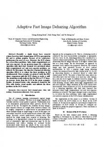
� � = 1 − � min��{�,�,�} �min ��(�) � �� �� , (0 < ω ≤ 1) (4) Where ω is an application-based value and it helps keep a very small amount of haze for the distant objects to make the haze-free image seem natural. It is 0.95 in this work. Moreover, the dark channel prior can be used to estimate the atmospheric light A more accurately than previous single image haze removal methods. B. Wavelet Transform In our experiments, we find haze images are usually smooth. Compared with haze-free ones, they are with more energy, higher luminance and smaller variance. Moreover, the hue of haze images is uniform and the number of the texture details is less than haze-free ones. In order to quantitatively analyse the effect of haze on images, we compute the mean lightness, mean energy and variance on different frequency components of haze and haze-free images from the Columbia Weather and Illumination Database [12]. We find the luminance and energy of the haze images increase about 75% percent compared with the haze-free ones, while 70% increasement attributed to the low-frequency component. Haze causes a 90% variance reduction of clear images, in which about 80% is owned to the low-frequency component. Consequently, haze mainly affects the low-frequency component of the image in the frequency domain. The images in Fig.1 confirm our observation. Based on this character of haze image, removing the haze across the whole image can simply be realized by dehazing the low-frequency component of the haze image. Wavelets decompose data into different frequency components, then study each component with a resolution matched to its scale, we employ wavelet transform to decompose the haze image. In this paper, wavelet transform is employed. The process of two-dimension discrete wavelet decomposition transform of an image is achieved by filtering the image with high-pass filter and low-pass filter, which is described detailedly in Fig.2. Firstly, the image is filtered with high-pass filter and low-pass filter horizontally and the filtered results are downsampled, producing two components; Then, the two components are filtered in vertical direction and the filtered results are also downsampled to produce the results of one-level wavelet decomposition. All in all, the image is high-pass filtered to " , produce detailed components LH, HL and HH, named �!,� # $ �!,� and �!,� in Fig.2. It is low-pass filtered to generate the final approximation component LL named %!,� in Fig.2. The reconstruction is the inverse process of the decomposition as described in Fig.2. In this paper, Haar wavelet transform is employed. C. Guided Filter In this paper, guided filter [11] is applied to refine the transmission map. It can be defined as follows: (5) &' = *� -' + .� , ∀2 ∈ �� Where i is the pixel indexˈ*� , .� are some linear coefficients assumed to be constant in �� centered at the pixel k. q is the filter output and I is the guided image. To decide the linear
276
coefficients, we find a solution to (5) by minimizing a cost function E that represents the difference between q and the input image p. The cost function can be defined as follows: E(*� , .� ) = ∑'∈67 ((*� -' + .� − 4' )# + 5*� ) (6) In (6), 5 is a regularization parameter, aiming at preventing the parameter *� from being too large. Linear regression can be used to determine the solution to (6). 8
*� = |9|
∑:∈9 �: ;: >?7 ;̅7
μ� , σ#�
7
B7C DF
, .� = 4̅� − *� G�
(7)
are the mean and variance of I and 4̅� is the Where mean of p in the window centered at the pixel k. We apply this linear model to all local windows in haze image. If a pixel is involved in many windows, the value of q will be different in those windows. A simple way is to get the average of all the possible values. Now we can get the filter output after computing the average of *� , .� for all patches in the image. (8) &' = *K' -' + .K' " " Where *K' = ∑��L: *� , .K' = ∑��L: .� . |6| |L|
(a) Left: Sunny image Right: Haze image
(b) Wavelet decomposition of (a). Fig.1 The influence of haze on image
Fig.2 Tow-dimension wavelet decomposition and reconstruction
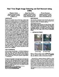
III. THE PROPOSED IMAGE DEHAZING METHOD A. Estimating the Transmission and Atmospheric Light As mentioned earlier, haze mainly affects the low-frequency component of haze image. Consequently, haze removal across the whole image is approximated and simplified by removing the haze in the low-frequency component of the degraded image. The specific steps of our algorithm to obtain the transmission map are as follows: Firstly, apply two-dimensional Haar wavelet transform to extract the low-frequency component -M and other high-frequency components of the haze image I as shown in Fig.3 (a). Then, dark channel prior and haze imaging model are
adopted to calculate the transmission map �M � of -M . Finally, employ guided filter to refine �M � . In this step, -M is employed as the guided image, and the transmission map �M � is treated as the input image. Based on the discussion in section 2.3, we could get the final refined transmission map �M by (8). As discussed in [8], the atmospheric light can be determined based on the dark channel. The top 0.1% brightest pixels are picked in the dark channel of -M , and then among all of these pixels, the pixel with the highest intensity in -M is used as NM . B. Recovering the Scene Radiance Based on the transmission map �M , atmospheric light NM of the haze low-frequency image -M and the haze imaging model, we can recover the scene radiance by taking the steps as follows: Firstly, from (1), when the transmission t(x) is close to zero, the direct attenuation term J(x)t(x) could be very close to zero. The directly recovered image J is prone to noise, hence the transmission t(x) must be restricted to a lower bound �O to make the haze-free image natural by preserving a small amount of haze in the dense haze areas. In this work, a typical value of �O is 0.1. Now the haze-free low-frequency image could be recovered by (9). � (Q)>� (9) �M (�) = P (Q),TP + NM RS�(TP
clear that the bigger the image is, the faster the proposed method will be. In order to quantitatively evaluate the performance of an image dehazing method, we use two criteria contrast and entropy of an image. The two criteria are evaluated for different image dehazing methods on the images shown in Fig.4. The result of comparison is described in Table 1. More results of comparison on the images from the USC-SIPI Image Database are listed in Table 2. From our visual observations on images shown in Fig.4, the haze-free images restored by the proposed method are better than that produced by the Dark Channel Prior and Guided Filter based method, which is consistent with the indicators described in Table 1.
(a)
Left: Haze image I.
Right: Result of WT.
U)
Where �M denotes the recovered haze-free low-frequency component of the haze image I, such as the image in the right side of Fig.3 (b). Then, based on the haze-free low-frequency image �M and other high frequencies obtained by Haar wavelet transform in section 3.1, we can reconstruct the scene radiance J with inverse Haar wavelet transform, in which the original low-frequency component -M is replaced by the haze-free low-frequency component �M . The images in Fig.3 (c) illustrate this step.
(b)Left: low-frequency haze image IV . Right: The dehazing result of IV .
(c)Left: Replace -M with �M . Right: The haze-free image J Fig.3 The intermediate results of the proposed method.
IV. EXPERIMENT RESULTS AND DISCUSSION In our experiments, the proposed algorithm is carried out by matlab on a PC with Intel Core 2 Quad Q8200. The images used are collected from flickr.com and the USC-SIPI Image Database. Fig.4 shows the results obtained by different image dehazing algorithms. Compared with the Dark Channel Prior with Guided Filter based method, the proposed approach is faster, maintaining relatively excellent performance. For the Dark Channel Prior with Guided Filter based method, there is about 75% of the runtime spent on computing and refining the transmission map of the original haze image, which are defined by (4) and (8). For an m x n image, the complexity of getting and optimizing the transmission map is O(mn). In the proposed approach, the algorithm of getting and refining the transmission map are only applied to the low-frequency component, extracted by the wavelet transform from the original haze image. As the size of the low-frequency component is a quarter of the original haze image, the runtime cost is dramatically decreased. Fig.5 shows the running time of our method and Dark Channel Prior with Guided Filter based method. It is
(a) Left: input images. Middle: our results. Right: results of dark channel prior with guided filter.
277
(1024x1024) 2.2.10 (1024x1024) 2.2.11 (1024x1024) 2.2.12 (1024x1024) 2.2.14 (1024x1024) 2.2.15 (1024x1024) 2.2.16 (1024x1024) 2.2.17 (1024x1024) 2.2.18 (1024x1024) 2.2.19 (1024x1024) 2.2.20 (1024x1024) 2.2.21 (1024x1024) 2.2.22 (1024x1024) 2.2.23 (1024x1024)
(b)Up: input image. Middle: our result. Down: results of Dark Channel Prior with Guided Filter. Fig.4 Comparison of different image dehazing methods.
Entropy Contrast Entropy Contrast Entropy Contrast Entropy Contrast Entropy Contrast Entropy Contrast Entropy Contrast Entropy Contrast Entropy Contrast Entropy Contrast Entropy Contrast Entropy Contrast Entropy Contrast Entropy
6.3657 19.4880 6.2469 19.9524 6.3521 21.6909 6.4425 25.7699 6.7071 19.2048 6.1589 24.6122 6.6132 29.6160 6.8501 23.4995 6.5754 17.8438 6.1841 25.1032 6.5571 29.1936 6.7670 21.1519 6.4041 17.1590 5.5603
6.4672 23.8749 6.3076 30.8418 6.9363 29.7287 6.6667 33.5140 6.9031 31.4031 6.5186 28.1245 6.4578 37.0462 7.1465 36.4401 7.0425 27.6850 6.7326 31.4948 6.5376 31.2129 6.9545 26.0444 6.6006 22.2389 6.2590
6.7946 29.0607 6.7110 40.8050 7.3755 30.8284 6.7863 44.2434 7.2834 33.4882 6.7006 35.7188 6.7849 41.8704 7.2748 47.8249 7.5198 38.0132 7.2809 40.8897 6.8311 38.0009 7.2647 33.0384 7.0203 30.0858 5.8152
V. CONCLUSION Fig.5 Running timing comparison between our method and Dark Channel Prior with Guided Filter (DCP+GF) method Table 1. The Comparison of Algorithm Performance Image Name Algorithm Contrast Entropy OI 43.8548 7.2689 Fig.4(a) DCP+GF 44.5208 7.3726 (500x332) OURS 55.5185 7.6599 OI 17.1590 5.5603 Fig.4(b) DCP+GF 22.2389 5.8152 (1024x1024) OURS 30.0858 6.2590 OI 23.0888 6.5250 Fig.4(c) DCP+GF 35.1951 7.0386 (327x1000) OURS 43.4855 7.4524 OI 36.4309 7.0427 Fig.4(d) DCP+GF 41.6837 7.3408 (360x500) OURS 55.2751 7.6869
In this paper, a novel single image haze removal algorithm based on dark channel prior has been proposed. By implementing Haar wavelet transform, the runtime cost is dramatically decreased, which paves the way for the future real-time application of the introduced algorithm. However, our work shares the common limitation of most image dehazing algorithms that the dehazing model may be invalid in some situations. A universal single image haze removal method based on state of the art models needs to be further investigated in the future. REFERENCES [1] E. J. McCartney, “Optics of Atmosphere: Scattering by Molecules and Particles[M],” New York: Jhon Wiley and Sons, pp. 23-32, 1976. [2] Y. Y. Schechner, S. G. Narasimhan, and S. K. Nayar, “Instant dehazing of images using polarization,” CVPR, pp.325-332, 2001. [3] S. Shwartz, E. Namer, and Y. Schechner, “Blind haze separation,” CVPR, pp.1984-1991, 2006. [4] S. G. Narasimhan and S. K. Nayar, “Contrast restoration of weather degraded images,” IEEE Trans. PAMI, pp.731-724, 25(6), 2003. [5] S. K. Nayar and S. G. Narasimhan, “Vision in bad weather,” ICCV, pp.820-827, 1999. [6] N. Hautiere, J. Tarel, and D. Aubert, “Toward fog-free in-vehicle vision systems through contrast restoration,” CVPR, 2007. [7] S. G. Narasimhan and S. K. Nayar, “Interactive deweathering of an image using physical model,” In IEEE Workshop on color and photometric Methods in computer Vision, October 2003. [8] K. He, J. Sun, and X. Tang, “Single image haze removal using dark channel prior,” in IEEE Conf. on Computer Vision and Pattern Recognition, pp. 1956-1963, 2009. [9] R. Tan, “Visibility in bad weather from a single image,” CVPR, pp.1-8, 2008. [10] R. Fattal, “Single image dehazing,” In ACM SIGGRAPH, pp. 1-9, 2008. [11] K. He, J. Sun, and X. Tang, “Guided image filter,” ECCV, 2010. [12] S. G. Narasimhan, C. “Wang, and S. K. Nayar. All the images of an outdoor scene,” In Proc. ECCV, 2002.
OI: Original Image. DCP+GF: Dark Channel Prior with Guided Filter.
Table 2. The Comparison of Algorithm Performance Image Name Criterion OI DCP+GF OURS 2.1.07 Contrast 20.1717 28.1000 35.2486 (512x512) Entropy 6.3332 6.4775 7.0044 2.1.08 Contrast 16.0652 26.9429 37.5584 (512x512) Entropy 6.0042 6.7856 7.2616 2.1.09 Contrast 20.8627 27.2180 35.0202 (1024x1024) Entropy 6.0193 6.1949 6.5732 2.1.10 Contrast 26.6704 36.3802 44.4012 (1024x1024) Entropy 6.5022 6.9614 7.2529 2.1.12 Contrast 20.3141 32.2958 38.5757 (1024x1024) Entropy 6.3117 7.0219 7.2728 2.2.02 Contrast 19.2066 25.6436 36.3691 (1024x1024) Entropy 5.7855 6.0139 6.5052 2.2.03 Contrast 16.1727 27.1312 36.8667 (1024x1024) Entropy 5.9331 6.7847 7.2252 2.2.04 Contrast 26.2254 30.0728 38.1846 (1024x1024) Entropy 6.6384 6.8898 7.2888 2.2.06 Contrast 12.0482 20.0727 31.1628 (1024x1024) Entropy 5.5226 6.0876 6.7025 2.2.07 Contrast 18.7379 27.1844 40.5446 (1024x1024) Entropy 6.2038 6.7598 7.3505 2.2.09 Contrast 20.3477 26.5817 32.4258
278