A Portable Device for the Translation of Braille to Literary Text Iain Murray
Andrew Pasquale
Department of Electrical and Computer Engineering
Department of Electrical and Computer Engineering
Curtin University of Technology Perth, Western Australia
Curtin University of Technology Perth, Western Australia
[email protected]
[email protected]
ABSTRACT This paper presents the development of a portable device for the translation of embossed Braille to text. The device optically scans a Braille page and outputs the equivalent text output in real time, thus acting as a written communications gateway between sighted and vision impaired persons..
Categories and Subject Descriptors H.5.1 [Multimedia Information Systems]:– audio input/output, evaluation/methodology. H.5.2 [U s e r I n t e r f a c e s ]:- auditory (non-speech) feedback, evaluation/methodology, theory and methods, user-centred design. H.5.3 [Group and Organization Interfaces]:collaborative computing, computer supported cooperative work, evaluation/ methodology. K.4.2 [Social Issues]:assistive technologies for persons with disabilities, handicapped persons/special needs.
General Terms Design, Experimentation, Human Factors.
Keywords Braille, portable machine translation, optical recognition…
1. INTRODUCTION The preferred means of written communications for many people with severe vision impairments is through tactile Braille mediums. While these persons can read and write using the Braille system, the majority of sighted persons in society can not, and thus there exists a written communications barrier between seeing and vision impaired persons. This problem is particularly apparent in the schooling system, where nowadays blind students are taught in mainstream classes. Many of these students perform assessment, tests and homework writing using the Braille medium. However, most teachers of these students are not Braille literate. One method presently used to overcome this difficulty is that the students work is first sent to trained Braille transcribers, where the Braille is translated to literary text and then sent back to the teacher before it can marked. This creates unnecessary delays and cost for the student, teacher and government. Problems also exists in the workplace where any information written by a Braille user that is
to be interpreted by other Braille illiterate persons, needs to be first translated by the Braille user themselves. To overcome this communications barrier, the device developed in this project provides a means by which Braille illiterate persons can read what a Braille user has written. The device is essentially a hand held scanner that is rolled along the desired Braille line, and in real time the equivalent decoded text is computed for output on a Liquid Crystal Display (LCD) or text to speech (TTS) hardware.. The device also has application for vision impaired persons who suffer Diabetic Peripheral Polyneuropathy (DPP). Diabetes a the major cause of blindness in Australia, and persons who suffer DPP lose touch sensitivity in their fingertips, causing considerable distress as they are unable to read even Braille mediums. (Similar conditions exist for geriatrics and persons suffering head injuries, Murray 1998). These persons could use this device to roughly feel the location of dots on the Braille line to operate the scanner, with the literary text equivalent spoken out in real time through the use of TTS with speaker output.
2. BACKGROUND 2.1 Past Developments There are many commercial text OCR products available and much research has been undertaken in text recognition, but little has been done to successfully produce a portable optical Braille recognition system. A software solution utilizing a flatbed scanner and standard PC is available [1] but lacks the portability and “real time” interaction as proposed here. Mennens et al [2] give an excellent summary of work in this field. Whilst of great interest to this work, the approach and technology used in [2] differs substantially from that is proposed in the work reported in this paper. This work is a continuation of initial investigations reported in [3] and [4].
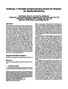
2.2 The Braille System Braille is a system of embossed (raised) signs, which are formed by six (or 8) dots arranged and numbered as in. Figure 1
Figure 1: The Braille Cell[2] Eight dot Braille is in limited use in the computer application area and is used in the display of text attributes. Therefore, eight dot Braille will not be considered further in this paper. Each dot can be set or cleared giving 2 6 –1 (63) possible characters in the code. As can be seen from this available number of combinations, not all characters may be represented directly by this system. (i.e. 26 upper case letters +26 lower case letter +10 numerals + punctuation marks greatly exceeds 63) [5]. Therefore, a system of contractions and abbreviations for words and letter combinations is used. This is commonly termed grade 2 or literary Braille. Each of these cells (Braille characters) is context sensitive, depending on the absence/existence of previous, following and symbol characters in the string being read. All dots on a Braille page should fall on an orthogonal grid. When texts are printed double sided (Interpoint) [2], the grid of the interpoint text is shifted so that the dots fall in between the primary side dots. This is illustrated in right hand side of Figure 1. For reference purposes, a particular combination may be described by naming the positions where dots are raised, the positions being universally numbered 1 through 3 from top to bottom on the left, and 4 through 6 from top to bottom on the right [8]. For example, dots 1-3-4 describes a cell with three dots raised, at the top and bottom in the left column and on top of the right column. In the original French language, in English and all other languages written in the Roman alphabet, that pattern would most often be used for the letter "m”. It can also have other meanings depending on language, Braille code and context. The basis of the various Braille codes for the world's natural languages is a straightforward assignment of most of the dot patterns to letters of the alphabet, punctuation marks and other symbols [6] This is done with a certain consistency, quite often with reference to Louis Braille's original assignments. For example, the letter "m" mentioned above would be used for ‘mu’ in Greek, and ‘mim’ in Arabic, both of which have an "m" sound. It is worth noting that it is not considered important for a Braille character to resemble the corresponding print symbol in "shape" [7]. In Braille, dot height, cell size and cell spacing are always uniform. As such, indicators in Braille must handle significant characteristics of the text (such as italics) used for emphasis and annotation. An exception is that of formatting, such as the centering of main headings, which is commonly used in Braille in much the same way as in print. As stated the 64 distinct characters are insufficient to cover all possible print signs and their variants, it is necessary to use multicharacter sequences for some purposes. Often this is accomplished by using certain characters as "prefixes" or "indicators" that affect the meaning of subsequent cells. For example, in English a dot 6 before a letter indicates that the letter is a capital, whereas otherwise it is understood to be lower case. [2]
The size of the Braille cell is such that only 25 lines of 40 cells each, that is 1000 characters, can fit on a page of the usual size, (11 inches wide by 11 to 12 inches deep). This contrasts with the 3500 characters that will fit on a standard, smaller, typed page. Moreover, Braille paper must be much heavier to hold the dot formation and the dots themselves considerably increase the effective thickness of a page. The result is that embossed Braille is very bulky. To mitigate this problem somewhat, most larger Braille books are published in "interpoint", that is with the embossing done on both sides of each sheet, with a slight diagonal offset to prevent the dots on the two sides from interfering with each other (Figure 1). Partly because of the bulk problem, and partly to improve the speed of writing and reading, the literary Braille codes for English and many other languages, employ contractions that substitute shorter sequences for the full spelling of commonly-occurring letter groups. Contractions such as TH may not be used across syllable boundaries. For example it may be used in the word THis but not in shorTHand [5]. This creates major problems in computer decomposition of grade-two Braille with respect to syllable boundaries. When contractions are used, the Braille is usually called gradetwo in contrast to grade 1 transcription where all words are spelled out letter-for-letter. In English, which has 189 contractions, almost all Braille is grade-two.
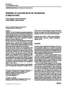
3. HARDWARE DESIGN 3.1 System Block Diagram The prototype of the system is displayed in Figure 2 and Figure 3. Note however that in the developed device all of the system components should be located all within a handheld unit for ease of use and portability.
Figure 2: Prototype System Implementation (View 1)
4. SOFTWARE DESIGN AND IMPLEMENTATION 4.1 DSP Software Operation The DSP’s computational tasks in the prototype device are to perform,
Figure 3: Prototype System Implementation (View 2)
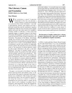
3.1.1 Image Capture System The image capture of the Braille medium is achieved by a camera system consisting of an illumination source, focusing lens and linear CCD photodiode array. These various parts can be seen in Figure 4.
1 Quadrature linear motion detection 2. Sampling of camera output frames 3. Fuzzy logic dot detection 4. Camera Angular Misalignment Correction 5. Braille Cell Compilation 6. Braille to text translation 7. Text Output Display The DSP control algorithm used for handling these tasks is interrupt driven and the software event flow is shown in Figure 6. The algorithm works as follows: -
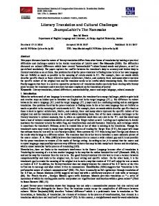
Figure 4: Handheld Scanner Assembly When in operation, the illumination source, constructed of a row of 4 LED’s, shines at a right angle to the Braille page causing shadows to form behind the raised dots of the Braille cell as seen in Figure 5.
Figure 5: Camera system in operation and dot shadow’s effect The selfoc lens used consists of a 2*12 array of micro – lens, designed to focus the Braille dot shadows image onto to the linear CCD photodiode array. The lens as seen in Figure 5, moves above the Braille cell in when the scanner is in motion, and as such causes no wear and tear on the Braille medium.
in its initial state, the codewheel interrupt is unmasked and camera frame interrupts (from camera SI pulse) are masked. the DSP waits for the a codewheel interrupt indicating scanner motion. Once interrupted, the DSP then determines if the scanner is moving in the forward direction and if it is, the codewheel interrupt is masked and the camera SI interrupt is unmasked to allow the SI pulse to interrupt the DSP when a relevant camera frame is ready to be sent When the camera interrupt occurs the DSP then samples the incoming frame Braille optical character recognition techniques then take place, and if possible, equivalent text output is sent to the host PC for display The camera SI interrupt is then masked, the codewheel interrupt unmasked, and the algorithm then repeats
4.2 Braille Dot Recognition To determine the existence of Braille dots from their shadows a reference magnitude was taken to be an average of a few samples that are at the edges of the camera’s field of view. Samples are then compared with this reference magnitude to gain a relative value to indicate whether that samples magnitude is affected by a Braille dot shadow. This allows the device to operate on many different types of Braille paper, and compensates for paper discolouring with aging. The reference magnitude can also be taken from the left or right hand side of the camera’s field of view to compensate for situations where Braille dot shadows may affect the reference sample regions. (Conveniently the vertical page height of the Braille cell, and thus range of Braille dot shadows is less the camera’s view height, so one side is always available as a correct reference). See Figure 8 for implementation. When a user is operating the device, it would be unreasonable to assume they would hold the scanners camera over the Braille line perfectly constant and stable when in motion. The device needs to be tolerant to changing location of dots within the camera frames so that the user can concentrate on understanding the text they are scanning, not on the scanning process itself. The DSP can allow for the varying location of Braille dots within the camera image by using fuzzy logic principles to ‘estimate’ whether a particular Braille dot is present. The range of allowed variability for particular dots is shown in figure 7 ,and is restricted solely by the height of the Braille cell and the camera’s limited field of view.
Braille cells (as shown), the DSP internal calculations are displayed in Figure 9 (following the context of the printf command in the Figure 8), with each new line representing the processing of a new camera frame. Clearly the operation of the fuzzy dot determination consistently locates Braille dot shadows despite the dynamic nature of the scanned Braille line.
Figure 8: Dot Recognition Software
Figure 6: DSP Algorithm Software Flow
Figure 9: DSP output when scanning a line of 6 dot Braille cells
Figure 7: Braille Dot Recognition Working Range The fuzzy variables are essentially sample magnitude scalars for the individual frame sample’s, given according to how likely they are to be affected by a particular Braille dot’ shadow within the camera image when the device is in motion. The fuzzy scalars were chosen using the Matlab charts for test base, and the existence of any of the 3 possible dots from one side of the Braille cell are indicated by ‘1’ in the ‘dot1’, ‘dot2’ and ‘dot3’ variables. (See implementation in Figure 8) In scanning a line of 6 dot
4.3 Scanner Angular Misalignment Correction Considering the camera system in the prototype uses a one dimensional (linear) CCD array, when moving over the Braille line the handheld scanner is often at an angle to the Braille cell. This results in the dots from one side of a Braille cell to appear in different camera frames. This is demonstrated Figure 10 when scanning a 6 dot Braille cell.
linear motion detection now comes to use in correlating slices of Braille cells with each other, since there is less distance in between the sides of a Braille cell than between two adjacent Braille cells. From the determined Braille cell a specific Braille code decompression algorithm to translate the context sensitive Braille characters into literary text for display output could then be applied. However for the device to be of practical application it needs to be able to decompress several different types of Braille codes, be it English Grade 2, Greek, Arabic, Maths, Music etc. It would be inappropriate to use a different scanner for all the different types of Braille codes encountered. An example of a unique Braille cell’s possible meanings follows,
Figure 10: Sequential appearance of Braille dots from angular misalignment To overcome this operational constraint, the DSP uses a simple technique where the successive found Braille dots from camera frames or logically OR’ed with each other. Over time, his allows dots from one side of the Braille cell to be represented in the same camera frame slice for correct optical Braille character recognition operation.
Hence to allow a truly universal device, a base system was devised which represents only the unique Braille cell combination found (not its meaning) for all Braille code decompression algorithms to use. The system assigns each unique Braille cell with a Binary Coded Braille Cell (BCBC) number which represents the combinations of dot present. BCBC is assigned using the following formula (also refer to figure 13), BCBC = dot1*25 + dot2*24 + dot3*23 + dot4*22 + dot5*21 + dot6*20, where dotX is one if the dot exists or zero if it doesn’t. Example’s of BCBC calculation are shown in Figure 13.
Figure 11: Angular Misalignment Correction Software This correction technique is however limited by the fact that at angles greater than 25 degrees, the CCD will pick up the Braille dot shadows from the other (left or right) side of the Braille cell, for which it cannot compensate. Below is displayed the ‘dot1’, ‘dot2’ and ‘dot3’ variables that are modified with the angular misalignment correction technique for the case when the device is scanning a line of 1-1-1-0-1-1 Braille cells,
Figure 13: Braille cell dot locations and respective dot number. The software algorithm to obtain the BCBC is simplified as follows,
The prototype debugging output is shown in figure 14 as the device was scanning a line of 1-1-1-0-1-1 Braille cells. Figure 12: A line of 1-1-1-0-1-1 Braille cell’s with angular misalignment correction Following the results a line at a time, it is apparent that there is least one point in time the when the misaligned dots are all represented in one slice variable, indicating the correct presence of dots from the Braille line.
4.4 Braille Cell Compilation Once a slice variable has been accurately created, representing the presence of dots from one side of a Braille cell, a previous slice representing the other side of the Braille cell is added, resulting in a unique Braille cell characterising the complete cell’s dot combination. The distance information obtained from quadrature
Note: (slice_left 8) + slice_right = (7*8) + 3 = 59 As may be seen, the cell compilation software provided correct and consistent operation.
Figure 14: determining a 1-1-1-0-1-1 Braille cell (111011 binary = 59 (BCBC))
Clearly, if the ambiguous character was in between 2 numerals, the character is representing decimal point and if it was not, would represent the letter ‘k’. The DSP in the same respect can determine the correct meaning of single sided Braille by applying simple rules. Considering there are only 14 single sided Braille cells in the 6-dot system, only 7 rules are required to distinguish cells which can be confused with each other. These rules need to be integrated into the Braille to text decompression algorithms to allow the device to handle the ambiguity in all types of Braille codes. Since the exact Braille character is unknown, the BCBC number system provides both possibilities for interface to the decompression algorithm. Cell compilation operation when scanning a line of single sided Braille cells is shown below.
4.5 Ambiguous Single Sided Braille Cell Compilation When a vision impaired person reading Braille encounters a single sided Braille cell, they have no ‘physical’ way of determining if the dots they are feeling belong to the left or right hand sided of the Braille cell, giving two possible meanings. Thus there exists physical ambiguity in Braille mediums in respect to single sided Braille cells. However, Braille codes are developed so that single sided Braille cells that could be confused with each other have totally different meaning, An example of this ambiguity is illustrated in Table 1 Braille Cell
Meaning
Braille Cell
Meaning
1 2
a (1) Comma, contraction “ea” Apostrophe
4 5
Accent indicator Contractions prefix
6
b (2) k, contraction “knowledge” Semicolon, contraction “bb” l, contraction “like”
4-5 4-6
Capital indicator, contractions prefix Contractions prefix Decimal point, Contractions prefix Letter indicator, Contractions prefix Contractions prefix
3 1-2 1-3 2-3 1-2-3
5-6 4-5-6
Table 1: Indistinguishable Single Sided Braille Cells in Grade 2 English Braille Hence when a Braille user encounters a single sided Braille, they subconsciously calculate both possibilities and depending on the context, choose the most appropriate meaning. For example, in Grade 2 English Braille consider the two physically indistinguishable single sided Braille cells.
Figure 15: DSP cell compilation, BCBC could equally be 56 or 7 (56@7)
4.6 Braille to Text Translation Once the binary coded Braille cell has been determined, the task of converting to literary text is dependent on the type of Braille code being scanned and is a relatively trivial and well understood task. Decompression algorithms for translating the context sensitive Braille medium to literary text have already been developed. For example, the algorithm developed by Paul Blenkhorn [5] consists of a state machine for control with switchable look up tables for
the different Braille codes (maths, Greek, English etc) to allow universal operation. For prototype testing purposes a greatly simplified decompression algorithm for translating Grade 2 English Braille into literary text was used. The algorithm substitutes Braille characters for literary text equivalent characters on a one to one basis. Hence the prototype’s operation for the case when scanning the alphabet could be examined for testing purposes. Refer to the screen capture shown in .Figure 16
Figure 17: Prototype operation when scanning a line of ‘X’ characters
5. PROJECT ACHIEVEMENTS
Figure 16: Prototype operation in scanning the English Alphabet In scanning the grade 2 English alphabet, the prototype system averaged an accuracy of 80.7 %. The accuracy is however heavily dependent on the users ability to keep the camera’s limited field of view over the Braille line and roughly straight. This is due to the fact that the prototype handheld device is quite large and clumsy in the hand, and rests on a one wheel tracking system when in motion, making it quite easy to twist, turn and roll off the Braille line (dots move out of the camera’s field of view). In a developed device however, the handheld ergonomics should be improved and ideally ought to run on a two or four wheel tracking system. This would prevent any twisting and turning of the scanner on the page and would force the scanner to move consistently in parallel with the Braille line, keeping the Braille dots within the vertical view range of the camera. The system delivered nearly 90 % accuracy when near ideal (straight and on the Braille line) scanner operating conditions were forced. Such operation is portrayed in Figure 17 when scanning a line of ‘X’ characters.
In the course of the project, quadrature linear motion detection was implemented and put to use to compensate for back scanning and hand jitter. A new, more flexible digital signal processor was programmed to determine the location of Braille dots from camera images of the Braille page using simple fuzzy principles. Software angular misalignment correction techniques were then developed to overcome some of the shortcomings of using a one dimensional camera system. Accurate compilation of the complete Braille cell from the located Braille dots was achieved and a simplified Braille to text translation algorithm was used to test the operation of the device in scanning an actual Braille page. Device testing proved integrated operation of the complete system, and thus a working prototype that could scan a Braille page and output the equivalent literary text in real time was developed. Testing also demonstrated the current system’s high sensitivity to correct scanner operation. In a developed device therefore, an improved wheel tracking system and ergonomic scanner need to be realised to achieve practical ease of operation.
5.1 Significant Aspects of the Project The most significant aspect of the project was the development of a proven architecture for a portable, real time Braille to literary text translation device. The unique optical method of operation has many inherent advantages in practical use and allows reasonable device cost. Thus a practical written communications gateway between seeing and vision impaired persons now exists. The device conveniently will also allow blind person’s suffering Diabetic Peripheral Polyneuropathy to continue to communicate through their preferred written medium.
5.2 Recommendations for Future Development The following possible developments that should have been implemented in this project, but where not due to schedule constraints are listed following. They are then left for the undertakings of future development.
5.2.1 Alternate Camera Assembly To fix the one dimensional camera angular misalignment and limited filed of view problems a new, larger two dimensional area CCD array could be used. This method would also not require a codewheel’s for motion tracking and with the use of an electronically variable lens, would allow the scanner to be held above the Braille page and ‘aimed’ at the desired Braille cells. In effect the device should become very easy to use and significantly more accurate. While this would make the system more expensive, previous difficulties with this approach being too computationally slow should be compensated for by now by the advent of new, faster and cheaper DSP’s.
Figure 18: CCD output when scanning the illumination peaks of 3 Braille dots.
5.2.2 Braille to Literary Text Decompression The complete decompression of Braille from its many forms of contractions, (be it maths, music, english US etc) can be accomplished giving practical use in the workplace and teaching scenarios. The decompression algorithm consists of a base state machine with switchable look up tables for the different types of Braille that are available. Functionality will also have to be provided on the scanner so that the user can choose the correct look up table for the Braille medium they are scanning. Conveniently this algorithm developed by Blenkhorn [5] was written in C, and using the 5402 DSP C compiler could be ported to the device with minimal modification and complexity. Note though, that single sided Braille cell determination rules will have to added. The software algorithm and C language implementation are given in Braille to Text Decompression.
Figure 19: CCD output when scanning the illumination shadows of 3 Braille dots.
6. REFERENCES [1] [2]
[3]
5.2.3 Ergonomic Developments At present the scanner assembly is quite difficult to operate due to a number of problems. Firstly, the prototype handheld device is quite large, so the user can not easily see the desired Braille cells they wish to scan, and it is quite clumsy ergonomically to use. Combined with the limited view of the camera system this results in severe impediment to the device accuracy of operation. The developed device needs to be reduced in size and made more ergonomic to hand held scanning, and the timing board, DSP and scanner will also have all have to be implemented in the same housing for ease of portability. The one wheel tracking system will also need to be replaced by a four wheel tracking system as mentioned previously, to keep the scanner correctly aligned with the Braille line in operation and to allow ease of use and improve accuracy.
5.2.4 Inter Point Braille Compatibility At present, the prototype system can not deal with interpoint Braille mediums, as described previously. By taking into account the arrival order of peaks and shadows however, the device potentially this capability. By considering only Braille dots that consist of an illumination peak followed by a shadow (indicating a raised dot) and disregarding dots with the illumination shadow arriving before the peak (indicating a dot depression from a Braille cell character on the back side of the Braille page), interpoint compatibility can be reassured. Refer to the figures 18 and 19 displaying consecutive CCD output frames when scanning 3 raised Braille dots. Scanning the dots depressions from dots made on the back side of the page would result in a reversal in the order of the camera frames.
[4]
[5] [6] [7]
Index, "OBR - Optical Braille Recognition," Index Braille Asia SDN BHD, 2006. J. Mennens, L. Tichelen, G. Francois, and J. Engelen, "Optical Recognition of Braille using Standard Equipment," IEEE Transactions on Rehabilitation Engineering, vol. 2, pp. 207-212, 1994. I. Murray and T. Dias, "A Portable Device for Optically Recognizing Braille – Part I: Hardware Development " presented at ANZIIS 2001, Perth Western Australia, 2001. I. Murray and T. Dias, "A Portable Device for Optically Recognizing Braille – Part II: Software Development " presented at ANZIIS 2001, Perth Western Australia, 2001. P. Blenkhorn, "A System for Converting Braille into Print," IEEE Transactions on Rehabilitation Engineering, vol. 3, pp. 215-221, 1995. I. Williams, Braille Primer with Exersises. London: Royal Institute for the Blind, 1969. P. Blenkhorn, "Personal Transcription Systems, ," presented at Computerised Braille Production, The Proceedings of the 5th International Workshop, Winterthur 1985.