coal through chemical leaching of 90 to 95 percent of the pyritic sulfur contained in the ..... As an alternate process step, the slurry from the flash tank (T-5) can.
A PROCESS DEVELOPMENT PLANT FOR TESTING OF THE MEYERS PROCESS
L.J. Van Nice, E.P. Koutsoukos, R.A. Orsini and R.A.
Meyers
TRW System and Energy Redondo Beach, CA 90278 I.
INTRODUCTION
Low organic s u l f u r coal can be desulfurized prior t o combustion u s i n g the Meyers Process(] $2) t o meet governmental requirements f o r s u l f u r oxide m i s s ions. The process removes up t o 80 percent of the total s u l f u r content of coal through chemical leaching of 90 t o 95 percent of the p y r i t i c s u l f u r contained i n t h e coal matrix w i t h aqueous f e r r i c s u l f a t e solution a t temperatures of 90" t o 130°C. The f e r r i c s u l f a t e content of t h e leach solution i s regenerated a t similar temperatures using a i r o r oxygen, and elemental s u l f u r and iron s u l f a t e s are recovered as reaction products o r alternatively gypsum can replace a portion of t h e iron s u l f a t e s as a product. The physical form of the coal remains unchanged; only pyrite and some inorganic materials a r e removed. The Environmental Protection Agency estimates t h a t 90 x 109 tons (82 x lo9 metric tons) of coal reserves i n the U.S. Appalachian Coal Basin can be reduced i n s u l f u r content by the Meyers Process t o levels which will meet New Source Performance Standards. Successful bench-scale testing(3.4) and romising engineering analyses(3.5-7) together with applicability testing(E.91, have led the Environmental Protection Agency t o sponsor the construction and operation of a test plant. Process chemistry, and t e s t plant design and operation will be described below. 11. PROCESS CHEMISTRY, KINETICS AND SCHEME
The process is based on the oxidation of coal pyrite with f e r r i c sulfate solution (Equation 1 ) . The leaching reaction i s highly s e l e c t i v e t o pyrite w i t h 60 percent of the p y r i t i c s u l f u r converted t o s u l f a t e s u l f u r and 40 percent t o elemental s u l f u r . The reduced f e r r i c ion is regenerated by oxygen o r a i r according to Equations 2 o r 3. FeS2 + 4.6 Fe2(S04)3 + 4.8 H20
+
10.2 FeSOq + 4.8 H2S04 + 0.85
1)
2.4 O2 + 9.6 FeS04 + 4.8 H2S04
+
4.8 Fe2(S04)3 + 4.8 H20
2)
2.3 O2 + 9.2 FeS04 + 4.6 H2S04
+
4.6 Fe2(S04)3
3)
a4
+
4.6 H20
Regeneration--can be performed either concurrently with coal pyrite leaching in a single operation or separately. The net effect of the process i s the oxidation of pyrite #ith.oxygen t o y i e l d recoverable iron, s u l f a t e sulfur, and elemental sulfur. The form of process products varies t o some extent with the degree of regeneration performed. Thus, Equations 1 and 2 lead t o the overall process chemistry indicated by Equation 4 with the products being a mixture of iron sulfates and elemental sulfur. Equations 1 and 3 y i e l d ferrous s u l f a t e , sulfuric acid, and elemental sulfur as indicated by Equation 5. FeS2 + 2.4 O2
+
0.6 FeS04 + 0.2 Fe2(S04)3 + 0.85
FeS2 + 2.3 O2 + 0.2 H20
+
FeS04 + 0.2 H2S04 + 0.85
41 5)
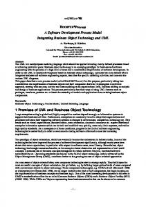
Several options e x i s t in product recovery. Iron sulfates may be recovered as pure solids by stepwise evaporation of a spent reagent slipstream w i t h ferrous sulfate being recovered f i r s t because of i t s lower solubility. Alternately, ferrous s u l f a t e may be recovered by crystallization and f e r r i c sulfate or sulfuric acid removed by liming spent reagent or spent wash water slipstreams. Iron sulfates my be stored as such for s a l e or may easily be converted t o highly insoluble basic iron sulfates (by a i r oxidation) or calcium sulfate (by low-temperature solid phase reaction) f o r disposal. Elemental sulfur may be recovered from coal by vaporization with steam or by vacuum or i t can be leached out with organic solvents such as toluene. Product marketability and product recovery economics will d i c t a t e the choice. Recovery economics may be influenced by quantity and concentration of product i n the process effluent streams which in t u r n are influenced by the pyrite concentration i n the coal and the desired extent of desulfurization. The process has been extensively studied a t bench-scale. Parameters investigated included coal top-size, reagent composition, slurry concentrat i o n , reaction temperature and pressure, and reaction time. Additional investigations completed or underway include concurrent coal leaching-reagent regeneration, product recovery, product s t a b i l i t y , and the e f f e c t of coal physical cleaning on process performance and economics. The process scheme depicted in Figure 1 is based on the bench-scale testing. Coal i s a ) crushed t o the desired s i z e f o r processing, b) contacted with h o t recycled reagent i n the Mixer (SO-100°C), c) leached of pyrite in the Reactor(s) with simultaneous or separate reagent regeneration, d ) washed with h o t water, and e ) stripped of elemental sulfur, dried and f i n a l l y cooled. The iron and sulfate sulfur are recovered from spent reagent s l i p s t r e a m prior t o reagent recycle. Figure 2 shows typical d a t a on pyrite removal rates from Appalachian coal as a function of temperature. Removal of 10-20 percent of the pyrite is obtained during slurry mixing and heat-up.
a5
1
Figure 1 .
Process Flow Schematic
90
80
70
$ 60 8
8 2 .
50
3 LL
Y
40
30
20
IO
/
I
0.5
Figure 2.
I 1.0
I I 1.5 2.0 REACTION TIME, HOURS
I
2.5
Temperature Effect on Processing of 14 Mesh Top-Size Lower Kittanntng Coal (33%w/w SlUrrieSl
86
3
Bench-scale data indicated t h a t the pyrite leaching r a t e from coal can be adequately represented by the empirical r a t e expression (Equation 6 ) .
where KL
= AL exp (-EL/RT),
Wp
= w t percent p y r i t e i n coal,
Y = f e r r i c ion-to-total iron r a t i o i n the reactor reagent, and AL and EL a r e constants f o r each coal and p a r t i c l e s i z e a t l e a s t over most of the reaction range.
The leach r a t e i s a function of coal type. Pyrite extraction rates vary considerably as detailed i n a study of the Meyers Process as applied t o U.S. coals(9) e.g., there was more than one order of magnitude d i f f e r ence between the f a s t e s t and slowest reacting coal i n attaining 75 percent pyrite removal a t 100°C. The reagent regeneration r a t e is governed by t h e r a t e expression (Equation 7 ) .
-
‘ R = - - =
dFet2 dt
K
P
(Fe“)’
O2
7)
where KR
= AR exp ( - E R / R T ) ,
P
= oxygen partial pressure,
O2
Fe”
= ferrous ion concentration i n the reagent solution, and
AR and ER a r e constants.
Engineering evaluation o f available data shows t h a t i t is preferable t o process f i n e coal ( < 2mm top-size) under simultaneous leaching-regeneration conditions i n the temperature range of 110-130°C until the majority of the pyrite i s leached out. Ambient pressure processing (approximately 100DC) is indicated f o r the removal of t h e l a s t few tenths percent of pyrite since t h e low Wp value substantially reduces t h e r a t e of f e r r i c ion consumption and, therefore, the need f o r simultaneous reagent regeneration. Ambient pressure processing appears t o be indicated a l s o f o r coarse coal (e.g., 10 millimeter top-size) f o r several reasons. I t i s d i f f i c u l t t o continuously feed a non-slurryable coal into and remove i t from a pressure vessel. I t is much e a s i e r and l e s s costly t o drain leach solution from t h e coal and pump i t into a small pressure vessel for regeneration. Also the
87
slower reaction rate with coarse coal would require much longer residence times and unreasonably large total volume f o r the pressure vessels. These engineering evaluations were part of the data used t o design the t e s t plant. 111.
TEST PLANT DESIGN AND OPERATION
A t e s t p l a n t sized t o process u p t o 8 metric tons per day of coal is being b u i l t , under the sponsorship of Environmental Protection Agency a t TRW's Capistrano Test S i t e . A p l a n t flow diagram is shown i n Figure 3. The f a c i l i t y w i l l be capable of on-line evaluation of the following c r i t i c a l process operations: 0
Pressure leaching of p y r i t i c sulfur from 150 micron t o 2 mn tops i z e coal a t pressures up t o 100 psig,
0
Regeneration of f e r r i c s u l f a t e both separately, f o r processing larger top-size coal or low pyrite coal, and in a single vessel with the leachi n g step f o r processing of suspendable coal,
0
F i l t r a t i o n of leach solution from reacted coal,
0
Washing of residual iron sulfate from the coal.
Iron s u l f a t e crystallization, elemental sulfur recovery and coaldrying unit operations will be evaluated in an off-line mode i n eauioment vendor pilot units. Leaching of 10 nun top-size coal can be evaluated i n an off-line mode i n an atmospheric pressure vessel installed i n the t e s t plant. Coarse coal grocessing (5-10 mn top-size) has been very promising in laboratory t e s t s ( 1. If t h i s approach proves out i n bench-scale evaluations, more extensive and on-line coal leaching units can be readily added t o the present t e s t plant. Processing f i n e coal allows the highest rate of pyritic sulfur removal, while processing coarse coal, although slower, allows lower cost coal dewatering units and the direct shipping of desulfurized coal product without need for pelletizing. The t e s t plant under construction a t the Capistrano Test S i t e i s a highly flexible f a c i l i t y capable of testing the numerous alternate processing modes of potential interest i n the Meyers Process. The flow diagram shown in Figure 3 presents an equipment t r a i n for continuous process testing of slurried coal. Fine coal ground t o t h e desired s i z e i s stored under nitrogen gas i n 1.8 metric ton sealed bins. As required, bins a r e emptied into the feed tank (T-1). Dry coal i s continuously fed by a live bottom feeder t o a weigh belt which discharges t h r o u g h a rotary valve t o the three s t a g e mixer (Stream 1 ) . The aqueous iron s u l f a t e leach solution (Stream 2) entqrs the mixer a f t e r f i r s t passing through a foam breaker (T-2). Steam i s added (Stream 3) t o r a i s e the slurry t o its boiling point. Foaming will occur in the early stages of mixing, b u t will cease when particle wetting ib complete. I t i s believed t h a t the mixing time and conditions necessary t o complete the wetting and defoaming of the slurry will depend on the coal type and s i z e and on the residual moisture i n the feed coal. To allow study of the mixing parameters, the mixer stages have variable volume, w i t h variable speed agitators and the feed f l w rates f o r coal, leach solution and steam can be varied over wide ranges.
88
IICU L M
ATMOS.
t
I
L
-
I-
Figure 3.
Test Plant Flow Diagram
89
The defoamed s l u r r y (Stream 4) i s pumped t o a f i v e stage pressure vessel (Reactor 1) i n w h i c h most of t h e p y r i t e r e n o v a l r e a c t i o n occurs. Some o f t h e p y r i t e r e a c t i o n occurs d u r i n g m i x i n g , b u t i n t h e m i x e r t h e r e a c t i o n r a t e slows r a p i d l y because t h e remaining p y r i t e (Wp) decreases and because t h e f e r r i c i r o n i s r a p i d l y being c o n v e r t e d t o f e r r o u s i r o n ( Y decreases). The pressure r e a c t o r overcomes t h e decreased r a t e i n two ways. F i r s t , i t increases t h e temperature (and pressure) t o increase t h e r e a c t i o n r a t e constant. Second, oxygen i s i n t r o d u c e d under pressure t o regenerate f e r r i c i r o n and m a i n t a i n a h i g h s o l u t i o n Y . The f l o w diagram shows t h a t steam and oxygen can be added t o any o r a l l o f t h e f i v e stages and t h a t c o o l i n g can be p r o v i d e d f o r any stage i f necessary t o remove t h e excess heat o f r e a c t i o n . The unused oxygen s a t u r a t e d w i t h steam (Stream 7) i s contacted i n a s m a l l pressure vessel (T-3) w i t h t h e feed l e a c h s o l u t i o n (Stream 5) t o p r o v i d e heated l e a c h s o l u t i o n f o r t h e m i x e r (Stream 2) and cooled v e n t gas. The v e n t gas from b o t h T-2 and T-3 a r e scrubbed i n T-4 t o remove any t r a c e s o f a c i d m i s t . The r e a c t i o n parameters o f importance have a l r e a d y been w e l l s t u d i e d a t l a b o r a t o r y and bench-scale i n batch mode. The t e s t p l a n t r e a c t o r w i l l accommodate t h e necessary s t u d i e s o f key parameters i n a continuous r e a c t o r a t coal throughputs between 2 and 8 m e t r i c tons p e r day. Parameters which w i l l b e s t u d i e d i n c l u d e : temperature, pressure, oxygen p u r i t y , s l u r r y c o n c e n t r a t i o n , i r o n s u l f a t e concentration, a c i d c o n c e n t r a t i o n , residence t i m e p e r stage, number o f stages, m i x i n g energy, t y p e o f m i x i n g , c o a l s i z e and type. The r e a c t o r can a l s o be used t o s t u d y l e a c h s o l u t i o n r e g e n e r a t i o n i n t h e absence o f coal. Reacted c o a l s l u r r y (Stream 8) a t e l e v a t e d temperature and pressure is f l a s h e d i n t o a g a s - l i q u i d separator vessel (T-5). The steam generated (Stream 9 ) i s condensed i n T-4 and t h e condensate p l u s any e n t r a i n e d a c i d m i s t i s removed w i t h t h e water. The r e s i d u a l s l u r r y (Stream 10) i s f e d t o a b e l t f i l t e r . The f i l t r a t e , w h i c h i s reqenerated l e a c h s o l u t i o n , i s removed from t h e coal s l u r r y through a vacuum r e c e i v e r (T-9) and pumped (Stream 12) t o a l a r g e l e a c h s o l u t i o n storage t a n k (T-6). The coal o n t h e f i l t e r b e l t i s washed w i t h w a t e r (Stream 11) and discharged from t h e f i l t e r b e l t . The wash w a t e r i s removed through a vacuum r e c e i v e r (T-10) and s e n t t o a l a r g e l i q u i d - w a s t e h o l d i n g t a n k (T-8) f o r subsequent d i s p o s a l . The f i l t e r i s a h i g h l y v e r s a t i l e u n i t which should p r o v i d e t h e d a t a necessary f o r scale-up. I t has v a r i a b l e b e l t speed, v a r i a b l e b e l t areas assigned t o washing, v a r i a b l e cake washing r a t e s , b e l t sprays i f needed t o c o n t r o l b l i n d i n g o f t h e pores i n t h e b e l t , and steam nozzles t o p r o v i d e f o r p a r t i a l cake d r y i n g . As a n a l t e r n a t e process step, t h e s l u r r y from t h e f l a s h t a n k (T-5) can be passed i n t o a secondary r e a c t i o n vessel (Reactor 2). A t t y p i c a l c o a l feed r a t e s , t h i s vessel can be f i l l e d i n about two hours and t h e n c l o s e d off, s t i r r e d and heated f o r any d e s i r e d p e r i o d o f t i m e b e f o r e being pumped t o the filter. Residence times up t o about 10 hours a r e a v a i l a b l e i n t h e p r i m a r y r e a c t o r , Reactor 1. T h i s secondary r e a c t o r can be used t o extend r e s i d e n c e times t o much longer t i m e s f o r examining t h e removal o f f i n a l t r a c e s of p y r i t e o r examining any o t h e r l o n g t e r m behavior. The s t i r r e d vessel a l s o can s e r v e t o r e p u l b t h e f i l t e r cake f o r a d d i t i o n a l c o a l washing studies.
90
The f i n a l item of major equipment i n t h e - t e s t plant i s the coarse coal contact vessel (Reactor 3). T h i s insulated and heated tank will hold a f u l l bin (about 1.8 metric tons) of coarse coal ( 5 t o 10 millimeter tops i z e ) . The principie use f o r t h i s vessel is t o convert the regenerated leach solution i n storage tank T-6 t o a more depleted solution i n t h e process feed tank. T-7. In general, the iron s u l f a t e leach solution i n the f i l t r a t e going t o tank T-6 will have a high Y because no secondary reactor was in use. For some t e s t conditions, the feed t o the process must be a t a lower Y t o simulate recycle leach solution from a secondary reactor. Passing a l l o r some portion of the solution through coal will lower the Y of the solution t o the desired value. T h i s vessel i s basically a coarse coal reactor and i f appropriate sampling ports and possible some flow distribution internals were added, i t could be used t o obtain design data f o r coarse coal processing. Solution tanks a r e sized a t about 50,000 l i t e r s t o provide f o r about a week of continuous operation on the same feed without recycle o r change. I t also provides f o r uniform leach solution and coal samples of a large enough s i z e f o r product recovery studies performed by equipment vendors. Operation a t t h e s c a l e of t h e t e s t plant will provide experience and data expected t o be adequate f o r the design of a demonstration-size commrcial plant. \ RE FEREXCES
1.
R. A. Meyers, J . W . Hamersma, J . S. Land and M. L . Kraft, Science, 177, 1187 (1972).
2.
R. A. Meyers, “Removal of P y r i t i c Sulfur from Coal Using Solutions Containing Ferric Ions,” U.S. Patent 3768988 (1973).
3.
E. P. Koutsoukos, M. L. Kraft, R. A. Orsini, R. A. Meyers, M. J . Santy and L . J . Van Nice (TRW Inc.). “Final Reoort Proqram f o r Bench-Scale Development of Processes f o r . t h e Chemicai Extraciion o f Sulfur from (May Coal ,” Environmental Protection Agency Series EPA-600/2-76-143a 1976).
4.
3 . W . Hamersma, E . P. Koutsoukos, M. L . Kraft, R. A . Meyers. G. J. Ogle, and L. J. Van Nice (TRW Inc.), “Chemical Desulfurization of Coal: Report of Bench-Scale Developments, Volumes 1 and 2,“ Environmental Protection Agency Series, EPA-R2-173a (February 1973).
5.
E.M. McGee (Exxon Research and Engineering Co.), “Evaluation of P o l l u tion Control in Fossil Fuel Conversion Processes. Coal Treatment: Section 1. Meyers Process ,” Environmental Protection Technology Series, EPA-650/2-74-009-k (September 1975).
6.
W. F. Nekervis and E. F. Hensley (DOWChemical, U.S.A.), “Conceptual Design of a Comnercial Scale Plant f o r Chemical Desulfurization of Coal,” Environmental Protection Technology Series, EPA-600/2-75-051 (September 1975).
7.
M. Rasin Tek (U. of Michigan), "Coal Beneficiation," i n Evaluation of Coal Conversion Processes, PB-234202 (1974).
8.
J. W. Hamersm and M. L. Kraft (TRW Inc.), "Applicability o f the Meyers Process f o r Chemical Desulfurization o f Coal: Survey o f 35 Coal Mines," Environmental Protection Technology S e r i e s , EPA-650/2-74-025-a, ISeptember 1975).
9.
U.S. Environmental Protection Agency, Office of Research and Development. Washington, DC, "Applicability o f t h e Meyers Process f o r Chemical Desulfurization of Coal: I n i t i a l Survey o f Fifteen Coals," by J . W. Hamersma, e t a l . , Systems Group of TRW, Inc., Redondo Beach, CA, Report No. EPA-650/2-74-025 (April 1974) Contract No. 68-02-0647.
92