Nov 24, 2008 - PAU in SeoSAT: A Proposed Hybrid L-band Microwave. Radiometer/GPS Reflectometer to Improve Sea. Surface Salinity Estimates from Space.
PAU in SeoSAT: A Proposed Hybrid L-band Microwave Radiometer/GPS Reflectometer to Improve Sea Surface Salinity Estimates from Space A. Camps(1), N. Rodríguez-Álvarez(1), X. Bosch-Lluis(1), J.F. Marchán(1), I. Ramos-Pérez(1), M. Segarra(2), Ll. Sagués(2), D. Tarragó(2), O. Cuñado(2), R. Vilaseca(2), A. Tomàs(3), J. Mas(3), J. Guillamón(4) (1)
Remote Sensing Lab., Dept. of Signal Theory and Communications, Universitat Politècnica de Catalunya Campus Nord, D4-016, 08034 Barcelona, SPAIN; IEEC CRAE/UPC (2) MIER Comunicaciones, Pol.Industrial Congost Parc. 4-S. 08530 La Garriga, Barcelona, SPAIN (3) NTE SA, Can Malé, s/n 08186 Lliçà d'Amunt, SPAIN (4) EADS-CASA Espacio, Avda Aragón 404, 28022 Madrid, SPAIN
Abstract— It is generally accepted that the best way to retrieve
Sea Surface Salinity (SSS) is by means of L-band radiometry (1400-1427 MHz). However, in addition to the polarization and the incidence angle, the SSS and the sea surface temperature (SST), the sea surface brightness temperature depends on the sea state. This work describes a hybrid L-band radiometer & GPS L1 reflectometer proposed to infer sea state information at similar surface roughness scales and therefore improve the sea state correction in surface salinity estimates. I. INTRODUCTION Sea state is the largest contributor to the deviations of the brightness temperature (∆TB) with respect to the flat sea model [1]. The sea state is usually parameterized in terms of the 10meter height wind speed (U10) and/or the significant wave height (SWH) [2,3], but none of them are fully satisfactory. The use of Global Navigation Satellite Systems (GNSS) signals reflected by the sea surface for altimetric applications was first suggested by Martín-Neira [4], and more recently for sea state determination using the so-called “waveforms” [5, 6]. The GPS signal is transmitted using a right-hand circularly polarized (RHCP) electromagnetic wave that, when scattered over the sea surface, becomes mostly left-hand elliptically polarized. Over a perfectly calm (flat) sea, the scattered signal comes from the specular reflection point, determined by the shortest distance between the transmitting GPS satellite and the receiver. However, when the sea surface is roughed, the scattered signals come from a wider region that enlarges with increasing sea state, in a similar manner as the Sun reflecting over the sea. If the scattering surface is a plane, the loci of constant delay (isorange) are a set of ellipses, and the loci of constant Doppler (isoDoppler) are a set of hyperbolae. Therefore each point over the surface has a particular delay and Doppler (actually there are two points with the same delay and Doppler). In radar, the ambiguity function [7] provides a measure of the similitude between a signal and a delayed version of it that may include a Doppler shift. In GNSS/R the
so-called Doppler-Delay Map (DDM) is equivalent to the ambiguity function in radar and it actually provides a measurement of the width of the area over which the GPS signals are scattered. The basic idea of the PAU (Passive Advanced Unit for ocean monitoring) instrument is to combine in a single instrument an L-band radiometer and a GPS reflectometer to provide collocated and simultaneous measurements of brightness temperature and sea state estimates from DDMderived observables so as to make the necessary corrections to the brightness temperature [8]. The PAU instrument concept and development has been funded by the European Science Foundation through the EURYI program [9]. This work describes the results of the Phase A study of a simplified space-borne version of it with only one receiver and a LHCP antenna as Secondary Scientific Payload of the SeoSAT/INGENIO (Spanish Earth Observation Satellite). II. PAU INSTRUMENT CONCEPT PAU is a new type of instrument, which is a hybrid of: • an L-band radiometer formed by an array of 4 × 4 dual polarization (vertical and horizontal) receivers [10] integrated behind a patch antenna, whose outputs are digitized and then properly calibrated and combined to produce several beams using a digital beamformer [11], • a GPS-reflectometer that uses the same hardware as the Lband radiometer, but the digital beamformer synthesizes beams pointing towards the specular reflection points of the GPS signals [12] while synthesizing a LHCP or a RHCP, and • a pair of commercial 8-14 µm thermal IR radiometers to measure the atmospheric downwelling radiance and the upwelling radiance from the sea surface + atmosphere. In order to use the same receivers for both the radiometer and the GPS-reflectometer, a new radiometer topology has been devised for each of the elementary receivers (Fig. 1), for the whole array each output is first added with the proper complex weight to create the synthetic beam.
978-1-4244-1987-6/08/$25.00 ©2008 IEEE
Authorized licensed use limited to: IEEE Xplore Customer. Downloaded on November 24, 2008 at 03:01 from IEEE Xplore. Restrictions apply.
As compared to a real aperture radiometer, instead of connecting the antenna output directly to the radiometer receiver, each receiving element is connected to the input of a Wilkinson power splitter that divides the signal in two signals that are in phase. However, the 100 ohm resistor of the Wilkinson power splitter that connects the two outputs also adds two noise signals that are 180º out of phase. Therefore, the signals at the input of the two channels of the radiometer are the sum and the difference of the antenna signal and the noise generated by the Wilkinson power splitter resistor. Once properly amplified, down-converted, sampled, and combined with the ones from other receivers to digitally form the beam(s), they are finally cross-correlated leading to an output that is proportional to the difference between the antenna temperature (TA) and the physical temperature of the Wilkinson power splitter resistor (Tph). That is, the system output is the same as the one of the Dicke radiometer, but the input signal is not chopped, so that it can be used to simultaneously track the GPS-reflected signal continuously by correlating it with a delayed replica of the C/A code which is frequency shifted to account for the Doppler.
improve receivers’ frequency response similarity), and digital power detector (to minimize thermal drifts). With these premises, and the mass (9.8 kg), volume (< 200 x 200 x 500 mm) and power consumption (< 20 W) envelopes the PAU in SeoSAT/INGENIO instrument was designed is four trays as shown in Fig. 2: • Tray 1 (Fig. 2a) includes the LHCP nadir-looking antenna output that is connected to the input of a Wilkinson power splitter through a switch, that commutes between the antenna signal and a noise source (3 levels) that it is used for calibration purposes. The outputs of the Wilkinson power splitter are then connected to two receiving chains that filter, amplify, down-convert and then split the signals in two branches each, the upper one for the GPS L1 signal (in blue), and the lower one (in yellow) for the radiometric signal. The first one is sampled at fs1=11 MHz (fIF1 = 8.25 MHz = fs1 x 3/4), while the second one is sampled at fs2=110 MHz (fIF2 = 22.5 MHz = fs2 x 1/4), which simplify the digital demodulation and low-pass filtering. The total gain is about 90 dB, with a noise figure smaller than 2.2 dB. • Tray 2 (Fig. 2b) includes one receiving chain, with just the GPS L1 branch and it is connected to a zenith-looking antenna to get the direct GPS signal. Tray 2 also generates all the clocks from a master reference of 11 MHz. • Tray 3 contains the EPC, and • Tray 4 the processor module. LO 2_PA U-GNSS R_1A [181,17 MHz]
LO1_PA U-RA D/GNS SR_1A [1386 MHz]
SMOS band
fs _P AU-GNS SR_1A [11 MHz ]
IF _ 1 PA T H [1 89 .4 2 ± 1 M H z]
RF PAT H [1 404 – 15 76,42 MH z]
I F _3 P AT H [8.2 5 ± 1 M Hz ]
S MOS band ATT_1 IF_FILT_1
LN A1
Fig. 1. Schematic of elementary PAU-RAD and PAUGNSS/R at one polarization (either horizontal or vertical).
A MP2
N OTCH _FILT
MIX _2
I F_FILT_2A
ATT_2 AMP3A
AM P4A
AMP3B
AMP 4B
AMP 5
I F_FI LT_3A
RF TES T PO RT
AMP 6
I F_F ILT_3B
IFA MP
IF _2 PA TH [18 – 37 MH z]
fs _PA U-RA D_1A [110MHz]
LO 2_PA U-GNSS R_1B [181,17 MHz]
LO1_PA U-RA D/GNS SR_1B [1386 MHz]
fs _P AU-GNS SR_1B [11 MHz]
+
RF TE ST PO RT SMOS band
IF _ 1 PA T H [1 89 .4 2 ± 1 M H z]
I F _3 PA T H [8.2 5 ± 1 M Hz ]
S MOS band 50 Ohm
ATT_1 IF_FILT_1
LN A1
LN A2
A MP2
N OTCH _FILT
MIX _2
I F_FILT_2A
AM P4A
AMP3B
AMP 4B
AMP 5
G PS band signal
A/D
ATT_2 AMP3A
I F_FILT_2B
AMP 1
L1-GP S band
I F_FI LT_3A
R F PAT H [1404 – 1576,42 MHz]
IF _2 PA TH [18 – 37 MH z]
AMP 6
SMO S band signal
A/D
A TT_3 L1-GP S band
a)
S MOS band signal
A/D
A TT_3 L1-GPS band
Wilkinson divider
GP S band si gnal
I F_FILT_2B
AMP 1
50 Ohm L1-GP S band
ANTE NNA
Correlat ed Noise S ource (2 levels)
III. PAU IN SEOSAT/INGENIO PAU in SeoSAT is a simplified version of the full PAU instrument, following the concept described in [9], but with only one receiver and a LHCP antenna with a 20º beamwidth. SeoSAT/INGENIO is the Spanish contribution to the EU GMES program. The platform will be in a Polar orbit (inclination = 98.9º) at 681 km height. The primary payload is an optical VIS-NIR sensor, and for the secondary payload a call for ideas among Spanish scientific community was issued in the Fall of 2006. On December 2006 it was selected for selected for phase A, which was developed during 2007. The objectives of PAU are fourth fold: - Scientific: • to determine the relationship between ∆TB at L-band and the DDM parameters to perform the necessary corrections to improve salinity retrieval, and • to determine the geographic statistics of RFI at L-band, - Tecnological: • to test the PAU instrument concept using modified LICEF (SMOS) receivers, and • to test new techniques and technologies, such as I/Q digital demodulation (to avoid quadrature errors, and perfectly match the I/Q branches perfectly matched in terms of receivers’ noise temperature and frequency response), digital LPF (to relax RF filter specs and
M IX _1
LNA 2
A/D
I F_F ILT_3B
IFA MP
f s_PA U-RA D_1B [ 110MHz]
b)
c)
d) Fig. 2. Block diagrams of the four trays of the PAU in SeoSAT/INGENIO instrument: a) Tray 1: nadir-looking hybrid radiometer-GPS reflectometer, b) Tray 2: zenithlooking GPS receiver, c) Tray 3: EPC, and d) Tray 4: Processor module.
As antennas, two arrays have been considered: a 7 element hexagonal array (as shown in Fig. 3a), and a 6 element hexagonal array (as the previous one, but without the central element). The dual-band antenna design is a trade-off between maximum main beam efficiency and maximum directivity so
Authorized licensed use limited to: IEEE Xplore Customer. Downloaded on November 24, 2008 at 03:01 from IEEE Xplore. Restrictions apply.
as to increase the SNR, but still having the glistening zone in the antenna footprint.
b)
a)
c)
d) Fig. 3. a) Antenna layout, b) Antenna co- and cross-polar pattern cuts, c) antenna co-polar pattern, and d) antenna cross-polar pattern.
Figure 4 presents an artist’s view of the PAU antenna in SeoSAT/INGENIO and the payload formed by four trays.
a)
b)
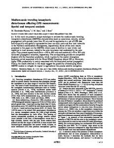
Fig. 4. a) Artist’s view of the PAU antenna (in green) in the nadir-looking face of the platform of SeoSAT/INGENIO as the primary payload, and b) view of PAU payload III. BRIGHTNESS TEMPERATURE CHANGES RELATIONSHIP WITH GPS REFLECTOMETER OBSERVABLES Since the relationship between brightness temperature and sea state is not yet fully understood, and parameterizations exist only for wind speed and/or significant wave height [2, 3], the relationship between ∆TB and the DDM parameters is studied here in terms of the wind speed only, keeping in mind that, when data will be available the link between must be made directly to avoid both electromagnetic emission modeling and sea surface spectrum modeling inaccuracies. Figure 5 shows two simulated DDMs for wind speeds 3 and 10 m/s, respectively. Note that, the rougher the sea surface
(more waves) the wider the area from where reflections arrive, which correspond to pixels with larger transit times (delays) and Doppler frequencies. This translates into a wider DDM. If, to avoid the need of an absolute calibration, the DDM is normalized so that the maximum is equal to one, it can be readily seen that the volume under the DDM, increases with the geometric mean of the upwind and crosswind standard deviation of the sea surface slopes. Figure 6a shows the dependencies of the volume under the DDM vs. 10 m height wind speed at different thresholds (0% means the whole infinite DDM is considered, 1 % means that the DDM has been cut at 20 dB below the maximum, and so on). Figure 6b shows the relationship between the ∆TB and the associated DDM volume. Since the SNR in GPS reflectometry is extremely low (typically -40 dB or even smaller) an important point is to estimate the number of coherent (1 ms) and incoherent averages that must be performed so as to infer the sea state information with enough accuracy. The number of coherent integrations is limited by the coherence time of the sea surface, which for moderate winds at L-band is on the order of 5 ms, and the potential degradation produced if the navigation bit changes within the integration period. The number of incoherent integrations is ultimatedly limited by the movement of the specular reflection point, due to the movement of the receiver and the GPS transmitter. Figures 7a, 7b and 7c show respectively the estimated DDM volume, the estimated ∆TB, and the error in the estimated ∆TB, in the presence of noise [13]. A 1 ms coherent integration time followed by 100 ms incoherent integration time is expected to provide enough accuracy in the estimation of ∆TB (< 0.1 K) up to wind speeds of 14 m/s, with a negligible displacement of the specular reflection point. IV. CONCLUSIONS This work has summarized the main results of the PAU payload in SeoSAT/INGENIO Phase A study conducted during 2007. PAU is a new instrument concept that hybridizes a new type of pseudo-correlation radiometer and a GPS reflectometer that work synergistically to provide sea state measurements to be used to correct for the deviations in the brightness temperature due to sea state variations. While the full PAU instrument is a complex 4 x 4 array with digital beamforming and polarization synthesis independently both for the radiometer and the reflectometer, PAU in SeoSAT/INGENIO consists of just one of these receivers connected to a LHCP antenna. Simulation results seem to indicate that with 1 ms coherent integration time, followed by 100 ms incoherent integration time, brightness temperature changes can be corrected with an error < 0.1 K for wind speeds up to 14 m/s.
Authorized licensed use limited to: IEEE Xplore Customer. Downloaded on November 24, 2008 at 03:01 from IEEE Xplore. Restrictions apply.
ACKNOWLEDGMENTS This work has been conducted as part of the award “Passive Advanced Unit (PAU): A Hybrid L-band Radiometer, GNSSReflectometer and IR-Radiometer for Passive Remote Sensing of the Ocean” made under the European Heads of Research Councils and European Science Foundation EURYI (European Young Investigator) Awards scheme in 2004, was supported by funds from the Participating Organisations of EURYI and the EC Sixth Framework Programme, and by the Spanish National Plan Project ESP2006-28462-E/ “Passive Advanced Unit (PAU) for Ocean Monitoring: A New Hybrid L-Band Radiometer/GNSS Reflectometer to Test New Techniques and Technologies to Improve the Quality Of the Salinity Retrievals in SMOS” (PAU in SeoSAT Phase A study).
[1]
[2]
[3] [4] [5] [6] [7]
Fig. 4. Simulated DDM for PAU in SeoSAT/INGENIO with a GPS satellite at zenith for wind speeds: a) 3 m/s and b) 10 m/s.
[8]
[9] [10]
[11]
a) b) Fig. 5. a) Wind speed dependence of the DDM volume and b) relationship between ∆TB and the DDM volume for different thresholds with respect to the maximum.
[12]
[13]
REFERENCES Font, J., G. Lagerloef, D. LeVine, A. Camps, and O.Z. Zanife, “The Determination of Surface Salinity with the European SMOS Space Mission,” IEEE Transactions on Geoscience and Remote Sensing, Vol. 42 (10), pp. 2196-2205, October 2004 Camps, A., J. Font, M. Vall-llossera, C. Gabarró, I. Corbella, N. Duffo, F. Torres, S. Blanch, A. Aguasca, R. Villarino, L. Enrique, J. Miranda, J. Arenas, A. Julià, J. Etcheto, V. Caselles, A. Weill, J. Boutin, S. Contardo, R. Niclós, R. Rivas, S.C.Reising, P. Wursteisen, M. Berger, and M. Martín-Neira, “The WISE 2000 and 2001 field experiments in support of the SMOS Mission: Sea Surface L-Band Brightness Temperature Observations And Their Application to Multi-Angular Salinity Retrieval,” IEEE Transactions on Geoscience and Remote Sensing, Vol. 42 (4), pp. 804-823, April 2004. Gabarró, C., J. Font, A. Camps, M. Vall-llossera, and A. Julià, “A new empirical model of sea surface microwave emissivity for salinity remote sensing;” Geophysical Research Letters, Vol. 31, L01309, January 2004. Martín-Neira, M., “A Passive Reflectometry and Interferometry System (PARIS): Application to Ocean Altimetry,” ESA Journal 1993, vol. 17. pp 331-355. Rius, A., J.M. Aparicio, E. Cardellach, M. Martín-Neira, and B. Chapron, “Sea surface state measured using GPS reflected signals,” Geophys. Res. Lett.,29(23), 2122, 2002. Soulat, F., M. Caparrini, O. Germain, P. Lopez-Dekker, M. Taani, G. Ruffini, “Sea state monitoring using coastal GNSS-R”, Geophys. Res. Lett., Vol. 31, No. 21 Skolnik, M., “Radar Handbook”, 2nd edition, Ed. McGraw-Hill, USA, 1990 Camps, A., X. Bosch-Lluis, J. F. Marchan-Hernandez, I. Ramos-Perez, B. Izquierdo, N. Rodríguez, “New Instruments for Ocean Remote Sensing: PAU Description and Analysis of PAU-Radiometer”, IEEE Trans. On Geoscience and Remote Sensing, Vol. 45 (10), pp: 3180 – 3192, Oct. 2007. http://www.esf.org/activities/euryi/awards/2004.html Ramos-Perez, I., X. Bosch-Lluis, A. Camps, J. F. Marchan-Hernandez, and R. Prehn, Design of a compact dual-polarization receiver for pseudo-correlation radiometers at L-band, Proceedings of the IGARSS 2006, Denver, Colorado, July 31-August 4, 2006. Bosch-Lluis, X., A. Camps, J. F. Marchan-Hernandez, I. Ramos-Perez, and R. Prehn, FPGA-based implementation of a polarimetric radiometer with digital beamforming, Proceedings of the IGARSS 2006, Denver, Colorado, July 31-August 4, 2006. Marchan-Hernandez, J. F. , I. Ramos-Perez, X. Bosch-Lluis, A. Camps, and R. Prehn, FPGA-based implementation of DDM-generator for GPSreflectometry, Proceedings of the IGARSS 2006, Denver, Colorado, July 31-August 4, 2006. J.F. Marchan-Hernandez, N. Rodríguez-Álvarez, A. Camps, X. BoschLluis, I. Ramos-Perez, E. Valencia, Correction of the Sea State Impact in the L-band Brightness Temperature by Means of Delay-Doppler Maps of Global Navigation Satellite Signals Reflected over the Sea Surface, IEEE Trans. On Geoscience and Remote Sensing, Vol. 46 (10), Oct. 2008, (in press).
c) a) b) Fig. 6. a) estimated DDM volume, b) estimated ∆TB, and c) error in the estimated ∆TB, in the presence of noise [13].
Authorized licensed use limited to: IEEE Xplore Customer. Downloaded on November 24, 2008 at 03:01 from IEEE Xplore. Restrictions apply.