914
IEEE TRANSACTIONS ON INDUSTRIAL ELECTRONICS, VOL. 58, NO. 3, MARCH 2011
A Real-Time-Linux-Based Framework for Model-Driven Engineering in Control and Automation George Doukas and Kleanthis Thramboulidis, Member, IEEE
Abstract—Model-driven engineering (MDE) is proposed as the next revolution in embedded-system development. It is a promising paradigm that provides the developer the abstraction level required to focus on the specific application and not on the underlying computing environments. Real-time (RT) Linux variants constitute a mature and stable platform that can be considered a strong candidate for RT applications in the control and automation domain. In this paper, a framework for the MDE of industrial automation systems is presented. This framework exploits the following: 1) the function block, a wellknown paradigm in the industrial automation domain, to provide the control engineer with the ability to construct its systems as aggregations of existing components and 2) the real-time Linux to execute the automatically synthesized executable. A prototype runtime environment is described, and a laboratory example application using a robotic arm is used to demonstrate the applicability of the proposed framework. Performance measurements are very promising, even for hard RT control applications. Index Terms—Function-block (FB) model, industrial automation, model-driven engineering (MDE), real-time (RT) Linux.
I. I NTRODUCTION
E
MBEDDED SYSTEMS (ESs) play an always increasing role in everyday life. The need for embedded devices in industrial automation systems also increases and becomes more demanding. At the same time, the development process of ESs is becoming more and more complicated. Traditional approaches that are used in the development process of these systems have already reached their limits; currently used methodologies and toolsets prove inadequate to address the needs of the development process of complex ESs. The development process of ESs is unsatisfactory and many years behind their desktop counterparts, as reported in [1]. Graaf et al. in [2] argue that currently used development technologies do not take into account the specific needs of ES development. It is widely accepted that new approaches should be established to meet the needs of the development process of today’s complex embedded industrial automation systems. Lee in [3] argues that the most pressing problem is how to adapt existing Manuscript received June 30, 2008; revised December 17, 2008 and April 14, 2009; accepted July 9, 2009. Date of publication August 21, 2009; date of current version February 11, 2011. The authors are with the Department of Electrical and Computer Engineering, University of Patras, 26500 Patras, Greece (e-mail: thrambo@ece. upatras.gr;
[email protected]). Color versions of one or more of the figures in this paper are available online at http://ieeexplore.ieee.org. Digital Object Identifier 10.1109/TIE.2009.2029584
software techniques to meet the challenges of the physical world and claims that the key challenge in embedded software research is to invent frameworks with properties that better match the application domain. Mature computer and software technologies, as well as best practices and methods from the enterprise and desktop domain, can be transferred into the embedded domain and properly exploited to allow the control engineer to more effectively build the systems of the future. Component-based development (CBD), as well as modeldriven engineering (MDE) [4], is among the key promising technologies in the embedded research domain. CBD has exceptional appeal in distributed software development [5]. It supports modular engineering practices in the same way that integrated circuits support the modular design of hardware. CBD has been integrated with metamodeling and domainspecific modeling languages to allow the developer to capture the domain knowledge [6]. The platform-independent models, which are created by the developer, are transformed next by specific transformation engines to platform-specific implementations that are ready for deployment and configuration. The production process that is based on the integration of CBD with MDE is more productive compared to the traditional approaches by identifying three discrete development roles described in [7]. Product-line architectures analyze commonalities and differences among systems on the same domain and define a common software infrastructure (a framework) for this domain. Component developers design components, either common or project specific, that capture the application logic. Finally, component integrators construct the system from existing components, attempting to satisfy functional and nonfunctional requirements. Adopting this trend, this paper presents a framework for the industrial automation domain. This framework exploits the component- and model-based-engineering paradigms to allow the control engineer to graphically define the model of the control application using the IEC61499 function-block (FB) model [8], [9]. The FB model provides abstractions of the problem space and facilitates the control engineer in expressing the designs in terms of concepts from the application domain. Modelto-model transformers are used next to automatically synthesize the executable code using RTAI, a real-time Linux variant, as the target execution environment. A prototype IEC61499compliant runtime environment was defined, and a laboratory example application using a robotic arm was developed to demonstrate the applicability of the proposed framework.
0278-0046/$26.00 © 2009 IEEE
DOUKAS AND THRAMBOULIDIS: REAL-TIME-LINUX-BASED FRAMEWORK FOR MDE IN CONTROL AND AUTOMATION
Performance measurements are very promising, even for hard RT control applications. This paper further enhances the work presented in [10] and builds on the earlier work presented in [11] by focusing on the implementation space of the model-integrated-mechatronic (MIM) architecture. Its main contributions are as follows: 1) the definition of a flexible implementation model for FB-based design models, with emphasis on the effective exploitation of RT-Linux implementation constructs; 2) the definition of a runtime environment that is required for the deployment and predictable execution of the proposed FB implementation model; 3) the analysis of the timing behavior of FB implementations. The proposed approach is in the context of the third generation of ES design that provides execution semantic independence during the design phase [12]. Other research groups, e.g., [13] and [14], are working in the direction of implementing FBbased control applications for the industrial automation domain. However, we are not aware of any published work that successfully utilizes MDE for the construction of industrial automation systems that should meet RT constraints and support runtime reconfigurability. The remainder of this paper is organized as follows. In the next section, background and related work is presented. Current trends in ES development are described, and the basics of the FB model and RTAI are given. The robotic-arm example application that is used in this paper to demonstrate the applicability of the proposed approach is described in Section III. In Section IV, the proposed real-time Linux framework is presented. Performance analysis and results are given in Section V, and finally, this paper is concluded in the last section. II. BACKGROUND AND R ELATED W ORK A. ES Development The gap between theory and practice in general-purpose computing is well known. Glass in [15] claims that, even though it is easy to determine the state of the art, it is very difficult to determine what the state of software’s practice is. Graaf et al. discuss in [2] the results of an inventory carried out on European companies on the state of software’s practice for ESs. They claim that the development process is unsatisfactory and many years behind their desktop counterparts and that “currently used development technologies do not take into account the specific needs of ES development.” Specific needs come from the fact that ESs differ from general-purpose computer systems, so their development process requires a “more holistic approach that integrates essential paradigms from hardware and software design and control theory” [12]. There is a trend in the embedded domain during the last years to exploit software engineering technologies of the generalpurpose-computing domain. Heck et al. in [16] give an excellent overview of new software technologies that can be useful for implementing and reusing complex embedded control systems. They also survey emerging technologies that can play a key role in the development process of the next generation of embedded distributed control systems. Component-based
915
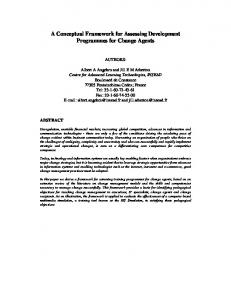
and model-driven developments receive major attention in this survey. A component-based architecture for the integration of industrial robotic platforms is presented in [17]. Moreover, it is well accepted that technologies from the general-purpose software domain cannot be used in the embedded domain without significant modification. For example, the mainstream component models such as DCOM, EJB, and .NET are not suitable for the ES domain. This is why a number of component models evolved during the last years to address the specific requirements of the development process of ESs [18]. Some of these are general purpose, such as CORBA-CCM (http://www.omg.org/docs/formal/0604-01.pdf), PECOS [19], the embedded object architecture [20], and DECOS (http://www.decos.at/), whereas others are domain specific such as the IEC61499 FB model, Ptolemy [21] and Giotto [22] for the control and automation domain, and SaveCCM [23] for vehicular systems. Integrated development environments (IDEs), which support the various component models, provide the tool support required to exploit the specific models in the development process. General-purpose and domain-specific IDEs are currently available, and a number of projects are on the way for the development of such IDEs. For example, the DECOS toolset and Archimedes engineering support system (ESS) [11] have been developed on top of the generic modeling environment (GME) [24], which is a configurable toolkit for creating domain-specific modeling and program synthesis environments. The former provides a model-based environment for the ES domain, while the latter is for the control and automation domain. Both of them attempt to exploit the benefits of component-based engineering and MDE in the domain of ESs. Archimedes ESS allows the control engineer to create the model of the control application using the well-known FB model, without worrying about the runtime environment and implementation details. A fully automated process based on model-to-model transformations is required to generate the corresponding implementation model. B. FB Model FB, a construct that is well known and is widely used by control engineers, was first introduced by the IEC1131 standard. However, languages defined by IEC1131, as well as supporting tools, do not address today’s needs for a distributed and agile development process in the control and automation domain. This is why the IEC61499 standard extended the FB concept to exploit in the Distributed Control System (DCS) domain many of the well-defined and already widely acknowledged benefits of concepts introduced by current software engineering practices such as object technology and CBD. The IEC61499 FB consists of a head and a body, as shown in Fig. 1(a), where the graphical representation of an FB type is given. Algorithms in the form of internal functions define the functionality of the FB; they process data inputs and internal data and generate data outputs. The sequencing of algorithm invocations is defined by the head, which accepts event inputs and produces event outputs. The execution control chart (ECC), a variant of statecharts, which consists of EC states, EC
916
IEEE TRANSACTIONS ON INDUSTRIAL ELECTRONICS, VOL. 58, NO. 3, MARCH 2011
Fig. 1. (a) IEC61499 basic FB-type graphical representation and (b) ECC.
Fig. 2. (Part of) FB network of the robotic-arm control application.
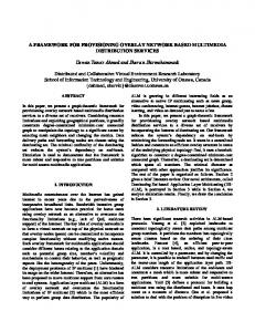
transitions, and EC actions, as shown in Fig. 1(b), is used to specify the behavior of the FB. An FB can be very simple, such as the one used to control a simple mechanical part, e.g., a valve, or very complex, such as the one used to control a robotic arm. Control applications are defined as networks of FB instances that are interconnected through event and data connections, as shown in Fig. 2, where part of the FB network diagram of the robotic-arm control application is given. The FB model adopts the control-push data-pull protocol [7] that is based on the dual connection of consumer and producer FB instances, i.e., one link for event and another for data. The producer FB instance produces fist the data and then sends an asynchronous message to the consumer FB instance to announce the presence of new data. The consumer FB instance uses a synchronous connection to receive the data. This protocol guarantees that synchronous connections will never block or wait for updates.
The IEC61499 standard provides basic execution semantics for the FB type, as well as for the FB network, but a lot of issues are still open, leading to incompatible runtime environments. Both monolithic and component-based approaches regarding the binary of the application are currently used for the execution of IEC61499-based control applications. However, the component-based approach has, for control systems, as argued in [16], several advantages over the traditional monolithic one. According to Szyperski [25], a monolithic application, in the binary level, is an application whose runtime is a single piece of executable code. The monolithic-application approach does not completely exploit the IEC61499 model that supports the execution of the control application on a network of interconnected devices and its redeployment. The control application is defined as an aggregation of interconnected FB instances that may be created and interconnected at the deployment time using the
DOUKAS AND THRAMBOULIDIS: REAL-TIME-LINUX-BASED FRAMEWORK FOR MDE IN CONTROL AND AUTOMATION
functionality provided by management FBs [8]. The FB must form an “atomic unit of distribution” [8]. Other researchers are also working to provide runtime environments for IEC61499-based DCSs. The function-block runtime (FBRT) (http://www.holobloc.com) is the first runtime environment for IEC61499-based control applications. FBRT utilizes Java, but it supports neither timeliness nor the runtime reconfigurability of the system. The method invocation paradigm, which is adopted for the implementation of event connections, and the nondeterminism of the Java platform make the environment inappropriate for RT applications and impose many restrictions to its use in real-world applications. ISaGRAF (http://www.icstriplex.com/), a well-known commercially available toolset for the IEC61131 standard, includes support for IEC61499 in its latest version. The proposed execution environment provides the first commercially available tool that supports it. The Fuber execution environment is under development at Chalmers University of Technology [13]. 4DIACRTE (http://www.fordiac.org/) is a runtime environment that is provided in a PC version and an embedded ARM7-based version [14]. These environments are not currently described in publicly available documents regarding the adopted implementation policies; performance measurements are not available. An FB-based model to support configuration and reconfiguration of DCSs is proposed, and its implementation on RT Java is discussed in [26]. However, neither a proof of concept nor a prototype implementation is provided for the aforementioned RT-Java-based approach. We are not aware of any other work that provides implementation models for IEC61499-compliant FB design models that meet RT constraints and support runtime reconfigurability. It should be noted that a RT-Java runtime environment is under development [27] in the context of the Archimedes system platform. C. Real-Time Linux The Linux operating system was initially designed for general-purpose computing systems, and thus, it was unable to cover requirements of RT embedded applications. During the last ten years, several variants of Linux have been developed to cover the needs of RT embedded software. The maturity, efficiency, and performance of these variants have reached to a level that allows RT embedded Linux to be considered as one of the top candidates for the ES domain. Moreover, mainline Linux kernel version 2.6.18 includes a set of RT enhancements that make embedded RT development even easier. RTAI (https://www.rtai.org/), which was selected for use in this paper, is an open-source hard RT Linux variant, which is released under the General Public License. It is based on a hard-RT microkernel that runs Linux as its lowest priority task. RTAI is provided as a minimal Linux kernel patch and a collection of Linux kernel modules, which results in a modular architecture. It uses a virtual interrupt mechanism that handles the interrupt enable/disable requests on behalf of the Linux kernel, so the RT kernel can never be preempted by Linux. The same mechanism is also utilized by the RT kernel to forward the hardware interrupts to Linux. This technique allows the RT
917
microkernel to run along with Linux in a completely transparent way that permits the use of a great number of standard Linux drivers, applications, and functions. RTAI provides performance characteristics [28] that make it very competitive with the best commercial RT operating systems, such as VxWorks, QNX, etc. RTAI represents, according to [29], a valid alternative to VxWorks in the RT system control, with network performance being a strong advantage when comparing RTAI with VxWorks. The RTnet network protocol stack (http://www.rts.uni-hannover.de/rtnet/) covers the RT communication requirements of RTAI, providing implementation of protocols such as UDP/IP, Internet Control Message Protocol (ICMP), and Address Resolution Protocol (ARP) over standard Ethernet hardware. Moreover, the Comedi acquisition driver (http://www.comedi.org/) provides a complete infrastructure to support RT process interfacing through ordinary Data-AcQuisition (DAQ) hardware. All the aforementioned characteristics make RTAI flexible, upgradable, and very attractive for use in the control and automation domain, with many positive experiences being reported so far, such as in [28]–[30]. RTAI is also successfully used in robot control for teaching [31], as well as to perform the computation of reference trajectories and system dynamics [32]. III. M ODELING THE A PPLICATION A laboratory robotic arm (http://seg.ece.upatras.gr/seg/dev/ RoboticArm.htm) is used as a running example in this paper to illustrate the proposed approach and demonstrate its applicability. The robotic arm is composed of three links. The position angle of each of the three links is sensed by a digital quadrature encoder mounted on the link’s motor axle. Each link is independently actuated by a dc motor. The legacy control application of the robotic arm manipulates each link separately. It consists of three PID controllers (one for each link), as shown in Fig. 3, which presents the abstract schematic diagram of a closed loop. The pulses of the encoder are counted by a DAQ card using a hardware up/down counter, which provides to the software an accurate reading of the axle’s position. The count reading is scaled to reflect the angle degrees of the current link, taking into account the gear’s ratio. The so-produced link’s position is connected to the PID controller. The desired angle that is provided to the PID controller for the specific link is calculated from the desired target position that is specified by the user and shown in Fig. 3 as “end-effector reference position.” The output of the PID is passed to a nonlinear filter in order to compensate for the motor friction forces and limit the controller signal according to the DAQ-card capabilities (±10-V output). The analog output of the DAQ card is connected to a high-frequency pulse-width-modulation-driven H-bridge power amplifier that provides adequate current to the dc motor. To construct the FB design model of the control application shown in Fig. 2, the following FB types were used. 1) PID_SIMPLE: The graphical representation of this FB type, which implements the PID functionality, and the corresponding ECC are shown in Fig. 1. The data inputs
918
IEEE TRANSACTIONS ON INDUSTRIAL ELECTRONICS, VOL. 58, NO. 3, MARCH 2011
Fig. 3. Abstract schematic diagram of the robotic-arm example application.
2) 3)
4)
5)
6)
of the FB type are as follows: 1) the PID parameters, i.e., the proportional gain KP , the integral gain KI, and the derivative gain KD; 2) the set point (SP ); 3) the process value (P V ); and 4) the sampling period DT . TRAN_FUNC: It encapsulates the transfer function of the nonlinear filter that is required to process the PID output. CALC_ANGLES: It is used to solve the inverse kinematics problem of the arm and calculate the desirable position of each arm link in terms of angle value. COUNT2RAD: It transforms the integer value of the input counter, which corresponds to a robotic-arm position sensor, to a real value that represents an angle in radians. NI6024E_COUNTER: This is an input mechanicalprocess-interface FB (MPIFB) that provides an integer value that represents the count of the position encoder’s pulses of the corresponding arm link. NI6024E_AO: An output MPIFB that is used to set the analog voltage value that drives the motor of the arm link.
Finally, to interface with the user, two Human Machine Interface (HMI) FB types were defined. The HMI FB types are used to interface the control application with the operator control panel, allowing the user to issue motion commands in the form of end-effector destination position coordinates, desirable PID parameters, and sampling period. More details on the design of the whole control application can be found in [33]. IV. R EAL -T IME -L INUX IEC61499 F RAMEWORK The proposed framework in this paper extends the functionality of the Archimedes system platform to exploit RT Linux in the MDE of distributed control applications. Archimedes ESS, an IEC61499-compliant ESS that is in the context of the MIM paradigm [11], was used as the basis for this framework. However, any other IEC61499-compliant ESS, such as the Corfu Function Block Development Kit, can be utilized since the interchange of FB design-level models is allowed through the use of XML. Fig. 4 shows the main constituent components of the proposed framework and their utilization in the development and execution of control applications. The main objective of this framework is to transform FB-based design specifications to appropriate implementations that can be executed on an RT
environment. The main components of the framework are as follows. 1) The FB implementation model framework, which enables the reuse of all our design decisions on the effective use of RT-Linux constructs in mapping FB-based design specifications to executable RT-Linux implementations. It is mainly composed of the “FB Implementation Model Library” that includes all the reusable elements of the implementation model. 2) The runtime environment, shown as RTAI-AXE in Fig. 4, which supports the deployment and execution of the automatically generated FB implementation model. This environment provides the infrastructure required to meet the deployment and redeployment needs, as well as the stringent nonfunctional requirements usually imposed by the nature of DCSs. Maximum permissible response times, minimum throughputs, and deadlines are among these requirements. 3) A set of model-to-model transformers to automatically generate the implementation model from the FB design model. These transformers are as follows: 1) the FB-type implementation generator, which transforms the FB-type design model to appropriate C++ implementations, and 2) the application assembly generator, i.e., the launcher, which supports the preparation and launching of the application on the target environment that is defined as a network of interconnected devices. The development and execution of a control application utilizing the proposed framework are achieved through the following process. 1) The component developer defines the project-specific components, such as CALC_ANGLES, as FB types (Fig. 1) using any IEC61499-compliant design tool. 2) The component integrator defines the application assembly as a network of interconnected FB instances (Fig. 2) of existing FB types using any IEC61499-compliant design tool. 3) The aforementioned design specifications are transformed through the model-to-model transformers of the framework to FB-type implementations in the form of C++ source code. This code is transformed next to dynamic loading libraries using the FB Implementation
DOUKAS AND THRAMBOULIDIS: REAL-TIME-LINUX-BASED FRAMEWORK FOR MDE IN CONTROL AND AUTOMATION
Fig. 4.
919
MDE using the proposed framework.
Model Library and the Target Runtime Environment Libraries. 4) Finally, the application is deployed and executed on the target IEC61499 runtime environment through the application launcher, which uses as input the XML application assembly specification.
A. Implementation Model Framework The implementation model framework is used to synthesize the RT-Linux implementation from FB-based design specifications. This section describes the most important design decisions for the mapping of IEC61499 design specifications to RTAI-compliant implementations. The most important classes of the implementation model framework are depicted in the class diagram shown in Fig. 5. BasicFBType, which is the key class of the framework, inherits the generic FBType class and captures the structure, behavior, and functionality of a basic FB type, as defined by the standard. The interface and the internal structure of the FB are described by providing a set of input/output/internal data variable declarations (VarDeclaration class) and input/output event declarations (EventDeclaration class). The BasicFBType class describes the behavior of the FB instance using an instance of the ECC class. ECC is defined as an aggregation of states (ECState class) and transitions between states (ECTransition class). Each state comprises a variable number of actions (ECAction class) that have to be performed upon entering the state. Performing an action means the execution of the corresponding algorithm that is represented by the Algorithm class and the generation of the related output event. Each state transition is characterized by a source and a destination state and a triggering condition, which is a Boolean expression composed of input events and/or input/output/internal data variables. Both state transition conditions and algorithm bodies
are represented as C++ operations. As shown in Fig. 5, the straightforward instantiation of FBType is not used for representing FB instances. Instead, the FBInstance class was defined and was associated with the FBType class through the “is of type” association. Common or project-specific FB types are defined as instances of the FBType class, whereas FB instances of the xexecution model are considered as instances of the FBInstance class. The adopted approach offers greater level of flexibility, compared to the straightforward instantiation of FBTypes, and can be implemented easier in environments that do not support dynamic class loading. This approach is also adopted by the Fuber runtime environment [13]. B. Runtime Environment For the implementation model to be executed on a network of interconnected devices allowing flexible deployment, redeployment, and reconfiguration of the FB application, the runtime environment should provide the ability to carry out the following. 1) Download FB types during runtime. 2) Create instances of selected FB types. 3) Create new event and data connections and delete existing ones. For the runtime environment to satisfy these requirements, the layered architecture shown in Fig. 6 has been defined. The main layers that constitute the runtime environment are as follows: 1) application execution (AE) layer; 2) industrial process-control protocol (IPCP) layer; 3) MPI layer; 4) configuration and deployment layer. The AE layer is the heart of the runtime environment and provides the services required for the deployment and execution of the application’s implementation model. The IPCP layer
920
IEEE TRANSACTIONS ON INDUSTRIAL ELECTRONICS, VOL. 58, NO. 3, MARCH 2011
Fig. 6.
Architecture of the runtime environment.
designer may bypass the MPI services and use the concept of service interface FBs proposed by the standard. Service interface FBs are implemented using the API of the process interface that is, in the case of RTAI-AXE, the Comedi driver. Finally, the configuration and deployment layer supports the deployment of the application and the remote configuration of the above layers. The remainder of this section focuses on the structure and implementation of the AE layer since it is mainly involved in the definition of the development process of the control application. As shown in Fig. 6, the AE layer is composed of the following basic modules.
Fig. 5. Class diagram of the implementation model framework (part of it).
provides the communication infrastructure required by IEC61499-compliant devices to interact with the following: 1) other devices to fulfill runtime communication requirements with the required quality of service (QoS); 2) ESS for deployment and redeployment; and 3) HMI stations to support the interaction with the operators. MPI provides a higher layer of abstraction on top of the process interface that is used by the standard. MPI implements the set of services that are required by ESS and devices to automatically setup and implement both the event and data connections of the application FB instances with the mechanical process. The use of MPI services leads to the following: 1) simplifies the FB design diagrams and decouples them from the physical architecture; 2) allows the developer to work on a higher layer of abstraction and concentrate only on the definition of the application logic; 3) results in a more flexible reconfiguration process that is required during the operational phase [34]. Moreover, it greatly facilitates the automation of the implementation model’s generation process. As an alternative, the
1) The FBType repository: This is a repository to store the FB types that are required to create the FB instances that constitute this part of the FB network that was assigned to a specific device. 2) The FB containers (FBCs): The concept of FBC was introduced to provide the runtime infrastructure for the execution of FB instances. Each FBC is an active entity, which means that it has its own thread of execution. Each FB instance is “injected” into the FBC that provides the QoS required for its execution. The required QoS of an FB instance is derived from the application requirements captured during the design time. The IEC61499 standard does not specify the way to capture these requirements in the FB diagram. However, this topic has already been addressed by IEC61499 researchers, e.g., [10]. Moreover, the Unified Modeling Language (UML) mechanisms to capture these requirements can be adopted, particularly in the case where the FB interaction diagram proposed in [35] will be adopted as a design-time artifact to provide a more human-readable way of representing the collaboration between FB instances. The execution of FB instances within an FBC is triggered by incoming events through the FBC’s event queue and follows a firstin–first-out run-to-completion scheme. The FBC supports
DOUKAS AND THRAMBOULIDIS: REAL-TIME-LINUX-BASED FRAMEWORK FOR MDE IN CONTROL AND AUTOMATION
the event- and time-triggered execution models. According to the event-triggered model, the FBC is triggered whenever a significant change of state, i.e., an event other than the regular event of a clock tick, is noted. In the time-triggered approach, the FBC is triggered at predetermined points in time [36] by setting it to periodic mode of operation using the rt_task_make_periodic function. 3) The event-connection manager (ECM): ECM, which is also an active entity, is responsible for the realization of event connections. It provides a flexible structure to model event connections in a way that promotes dynamic configuration and reconfiguration, even during runtime. ECM accepts in its input event queue events that are generated by publisher FB instances. It forwards the events to the FB instances that have been registered as subscribers. 4) The data-connection manager (DCM): DCM is a passive entity that acts as a protected repository of data variables and supports the realization of data connections. DCM promotes reconfiguration based on a dynamic and flexible mechanism for the definition of data connections. For the implementation of the proposed framework on RTAI, we have selected to use LinuX RT (LXRT), an extension of RTAI, which provides a programming interface for the development of hard RT applications from the Linux user space. LXRT makes the development process easier and minimizes the risks of kernel-space programming. It allows Linux threads to operate in two modes: soft and hard RTs. To operate in soft RT and favor over other common threads, a Linux thread should be registered as RT, utilizing the rt_task_init function. This allows the thread to use the LXRT API, even though it is still handled as a Linux thread. Any common Linux system call, even dynamic memory allocation calls, can be used. A softRT thread can change its mode to hard RT by a call to the rt_make_hard_real_time function, assuming that it has locked its allocated memory, by calling the mlockall function. The thread remains, in this mode, inside the protected user-space address context, but it is executed as an RTAI kernel hard-RT task. A thread in this state can make use of the RTAI/LXRT API but should not issue any ordinary Linux system call. Fig. 7 shows the implementation details of the proposed architecture over RTAI/LXRT. All active entities of the AE layer are implemented as hard-RT threads, whereas the configuration and deployment module operates in soft-RT mode and utilizes the basic Linux network protocol stack to support remote services. The MPI module is build over the Comedi acquisition device driver, whereas the IPCP module utilizes the RTnet protocol stack through its RT network interface device, i.e., rteth0. It must be noted that RTnet supports a mechanism to tunnel non-RT traffic, such as TCP/IP, over the same networking infrastructure by providing a virtual network interface to Linux (vnic0), thus allowing a single-cable solution for both RT and non-RT traffics. The solid line in Fig. 7 indicates an RT communication path, whereas the dotted line represents a non-RT path. Finally, it must be noted that, even though RTAI/LXRT supports dynamic memory management, this takes place only
921
Fig. 7. Implementation details of the runtime environment.
during the initialization of the execution environment to preserve determinism. During this stage, all the memory ever needed is allocated through appropriate lightweight memorypool mechanisms, thus allowing the pseudodynamic management of memory during reconfiguration operations. V. P ERFORMANCE A NALYSIS AND R ESULTS In this section, the timing behavior of IEC61499 implementations is analyzed, and the obtained benchmarking results through the proposed RTAI-based 61499 runtime environment are presented. The objective of this work is to demonstrate the timing characteristics of the proposed framework and contribute to the performance analysis of IEC61499 implementations. The worst case execution time (WCET) of any basic FB type can easily be calculated using the FB instance performance analysis measurements, while the end-to-end response time of the control application can be calculated using the FB network performance analysis measurements and the WCETs of FB instances that constitute a closed loop. A. Hardware and Software Test Bed The hardware test bed used in this performance analysis is composed of an embedded board alix1c (http://www. pcengines.ch/alix1c.htm) with a 500-MHz AMD Geode LX800 CPU, a 256-MB SDRAM, and a compact flash. The device was equipped with RTAI 3.6, RTnet 0.9.9 and Comedi 0.7.76, over Debian Linux 4.0 (Etch) running an ADEOS-patched version of Linux kernel 2.6.22. The latest version of our prototype implementation of RTAI-AXE, i.e., version 1.0, was installed and used in the test bed. B. FB Instance Performance Analysis The state transition diagram of Fig. 8, which describes the behavior of the FB instance, was used for the analysis of the performance characteristics of the FB instance. According to the control-push data-pull protocol that is adopted by the FB model, the FB instance is blocked in the idle state (S0), waiting for an event at its event inputs. The presence of an event at the event inputs of the FB instance fires transition t1. During this transition, sampling of the input data of the FB instance is
922
IEEE TRANSACTIONS ON INDUSTRIAL ELECTRONICS, VOL. 58, NO. 3, MARCH 2011
Fig. 8. State machine for the execution of basic FB instance [8].
Fig. 10. Evaluating (a) transitions and (b) perform-action time measurements.
Fig. 9. (a) Read and (b) write data time measurements (in nanoseconds).
performed (data pull), and the internal data input variables are updated so as to be used in subsequent calculations. During S1, the transitions of the current state of ECC are evaluated. If a transition fires, i.e., its condition evaluates to true, transition t3 is fired. This means that the duration of S1 depends on the number and the type of transitions. During S2, the actions that are associated with the new state of the FB instance’s ECC are executed. Each action is performed by executing the associated algorithm, if any, and issuing an event at the associated event output. Transition t4 is fired after the execution of the associated actions, and the FB instance enters the S1 state where the transitions of the current state of ECC are evaluated again. If a transition fires, t3 is activated; otherwise, t2 is activated, and the FB instance enters the S0 state. The following benchmark tests have been defined and executed. For each test, 10 000 samples were collected, and the average, standard deviation, and 99% upper bound are reported. 1) Read and write data benchmarks: These benchmarks examine the following: 1) the input-data sampling time as a function of the number of data to be sampled during transition t1 of the FB instance execution state machine and 2) the time for performing the output-data write operation. The number of input data related to a specific event is defined through the “WITH” qualifier. Fig. 9(a) shows the average, standard deviation, and 99% upper bound of the time measurements obtained. For the realization of the aforesaid benchmarks, a simple test FB type has been utilized, which has a set of input and output events with different numbers of related 4-B-long input and output data, respectively. The FB instance has been executed periodically in a series of tests, triggering different event input each time and measuring both read and write data operations. 2) Evaluating transition benchmark (S1): This test measures the duration of the S1 state where the evaluation of the
transition conditions of the current state is performed. For the realization of the benchmark measurements, a dummyFB type was used. This FB has seven input events named ei, where i = 1, 2, . . . 7, and no input data. Its ECC is composed of eight states, i.e., the “Start” state and seven other states named si, where i = 1, 2, . . . 7. The ei event fires the transition from the “Start” state to the si state. One dummy algorithm is assumed with just a return statement and only one event per EC action. The results of this benchmark, which is shown in Fig. 10(a), reveal, as expected, a linear relationship of the transition evaluation time with the order of the transition, assuming that the computation time of the corresponding Boolean expressions is negligible. The performance results of dummyFB can be used to calculate the execution time of any basic FB type of the application, assuming that the WCETs of its algorithms are available. 3) Performing action (S2) benchmark: This test measures the duration of the S2 state of the state machine of Fig. 8. The S2 duration depends on the number of actions, the algorithm execution time, and the output event firing time. Assuming dummy algorithms and zero event-output firing delay, which is going to be measured by another benchmark, the test-bed results shown in Fig. 10(b) are obtained. C. FB Network Performance Analysis For the FB network performance analysis, the event dispatch latency and the total event-connection processing latency within ECM, as listed in the following, are presented. The dataconnection latency was measured in the context of the read-data benchmark of the FB instance performance analysis. 1) Event dispatch latency benchmark: This test measures the time from when the output event of an event producer FB is fired to when the corresponding consumer FB receives the event and gets awaken. This measurement includes putting the produced event in ECM’s queue, processing it within ECM and forwarding it to the target FBC event queue that results to the awakening of the target FBC thread. An average time of 63.1 µs with a standard
DOUKAS AND THRAMBOULIDIS: REAL-TIME-LINUX-BASED FRAMEWORK FOR MDE IN CONTROL AND AUTOMATION
Fig. 11. Event processing within ECM.
deviation of 24 µs, a 99% upper bound time of 66.4 µs, and a maximum time of 153.9 µs were the results of this benchmark. 2) Event-connection processing latency within ECM benchmark: This benchmark measures the time from when ECM resumes execution, as a result of receiving an event in its queue, to when the event’s processing is finished, i.e., the event is delivered to all its destinations, realizing all the event connections in which the event participates. The test-bed results of this benchmark are shown in Fig. 11. D. Deployment and Redeployment Performance Analysis Deployment and redeployment sessions are based on the following key operations: 1) load an FB type; 2) create/delete an FB instance; and 3) create/delete an event or data connection. From these operations, only the creation and deletion of connections are considered to be RT critical because they require the reconfiguration of ECM and DCM during runtime. FB instances, once they are disconnected, can be safely deleted without affecting the application. The creation of an FB instance raises a problem when it is to be injected to an already running FBC. The average value of the FB instance creation time was measured to be 20 µs. Creation of an event connection has an average time of 1.87 µs, while its deletion has an average value of 1.8 µs, both with a standard deviation of about 0.5 µs. Similar measurements were obtained for data connections since the same mechanism was used in their implementation. E. Comments on the Measurements Studying the test-bed results of the previously described benchmarks, we observe a linear trend that indicates a predictable behavior and microsecond-level delays that reveal a relatively good performance. It must be noted that there has been an irregular behavior of the maximum time values, which was below 1% of the measurements taken, although not shown in the presented graphs. This uncommon behavior has been identified as an RTAI/LXRT irregularity caused by various hardware and Linux kernel configuration reasons, reported as “latency killers” in RTAI user’s manual. It is expected that a better Linux kernel configuration and a proper RTAI calibration will remove this predictability problem. It should also be noted that for the FB network performance measurements the FBCs operated in nonperiodic asynchronous mode, where their input-event queues were set to be blocking. If
923
the periodic mode had been used instead, the event-connection processing delay would be much smaller, as accessing the FBC input-event queue from ECM is simpler. As a mater of fact, when performing the event-connection processing benchmark in ECM while the target FBCs are set to periodic mode, the resulting average delay for a single-event connection was as small as 2.2 µs. The benchmark results obtained in this section were used to analyze the experimental performance measurements of the robotic-arm control application. For example, for the response time of the main closed loop of a link that crosses the five FB instances of the bottom half of the Fig. 2 FB diagram, the following measurements were taken: average of 358 µs, standard deviation of 13.6 µs, and maximum of 554 µs. This means that the system may support sampling rates of 2–3 kHz, for the control of a single link, or rates of 0.7–1 kHz for the control of the whole arm. For the aforementioned measurements, each FB had its own FBC, and all FBCs were set to event-triggered mode. The aforesaid measurements of the robotic-arm control application are consistent with the performance measurements of FB instance and network performance analysis. It should be noted that the event communication overhead for this closed loop has an average value of 4 × 63 = 252 µs. For the case of more stringent RT constraints, alternative designs that avoid the overhead imposed by the decomposition of the application logic to several components may be adopted. Such an alternative design for the robotic-arm control application may capture in one FB type (LINK_CONTROL) the whole application logic that was distributed to the five FB instances of the FB diagram shown in Fig. 2 (bottom half). In this case, the LINK_CONTROL FB type will capture the control logic of the whole link of the robotic arm. As it was expected, a significant improvement in performance is obtained. For the response time of the main closed loop, the following measurements were taken for this design: average of 69 µs, standard deviation of 2.5 µs, and 99% upper bound of 72 µs. VI. C ONCLUSION Component-based engineering and MDE improve the development process of ESs in control and automation. They allow the developer to describe the system with a modeling language without worrying on the early stages of development about the specific execution platform nor the implementation details. The IEC61499 FB model, which is a promising technology to address the always increasing demand for agile manufacturing, was adopted to define a framework based on real-time Linux for the MDE of control and automation systems. Current trends in software engineering can be exploited in a transparent way by control engineers through the proposed approach. The FB construct is used as the main building block for constructing the software counterpart of the mechatronic component that is the basic component for the construction of next-generation mechatronic systems. The proposed approach allows the control engineer to ignore all the complexities that are inherent in runtime environments and communication subsystems and concentrate on the actual problem to be solved. It provides an automatic transformation of FB-based design specifications to
924
IEEE TRANSACTIONS ON INDUSTRIAL ELECTRONICS, VOL. 58, NO. 3, MARCH 2011
RT-Linux code that can be deployed and executed on a network of interconnected devices equipped with a proper runtime environment. The use of RT Linux as implementation platform allows the seamless integration between automation and business logistics, as well as Internet and Web-enabled remote development, diagnostics, and maintenance. The test results regarding performance characteristics were very promising for the acceptance of the IEC61499 standard in the control and automation domain. R EFERENCES [1] A. Ibrahim, L. Zhao, and J. Kinghorn, “Embedded systems development: Quest for productivity and reliability,” in Proc. 5th ICCBSS, Los Alamitos, CA, Feb. 2006, pp. 13–16. [2] B. Graaf, M. Lormans, and H. Toetenel, “Embedded software engineering: The state of the practice,” IEEE Softw., vol. 20, no. 6, pp. 61–69, Nov./Dec. 2003. [3] E. A. Lee, “What’s ahead for embedded software?” Computer, vol. 33, no. 9, pp. 18–26, Sep. 2000. [4] D. Schmidt, “Model-driven engineering,” Computer, vol. 39, no. 2, pp. 25–31, Feb. 2006. [5] A. Repenning, A. Ioannidou, M. Payton, Y. Wenming, and J. Roschelle, “Using components for rapid distributed software development,” IEEE Softw., vol. 18, no. 2, pp. 38–45, Mar./Apr. 2001. [6] K. Balasubramanian, A. Gokhale, G. Karsai, J. Sztipanovits, and S. Neema, “Developing applications using model-driven design environments,” Computer, vol. 39, no. 2, pp. 33–40, Feb. 2006. [7] A. Childs, J. Greenwald, G. Jung, M. Hoosier, and J. Hatcliff, “CALM and Cadena: Metamodeling for component-based product-line development,” Computer, vol. 39, no. 2, pp. 42–50, Feb. 2006. [8] Function Blocks, Part 1–Part 4, Int. Std. IEC61499, Jan. 2005. [9] V. Vyatkin, Z. Salcic, P. S. Roop, and J. Fitzgerald, “Now that’s smart!” IEEE Ind. Electron. Mag., vol. 1, no. 4, pp. 17–29, Winter 2007. [10] G. S. Doukas and K. C. Thramboulidis, “A real-time Linux execution environment for function-block based distributed control applications,” in Proc. 3rd IEEE Int. Conf. Ind. Informatics, Perth, Australia, Aug. 2005, pp. 56–61. [11] K. Thramboulidis, “Model-integrated mechatronics—Towards a new paradigm in the development of manufacturing systems,” IEEE Trans. Ind. Informat., vol. 1, no. 1, pp. 54–61, Feb. 2005. [12] T. Henzinger and J. Sifakis, “The discipline of embedded systems design,” Computer, vol. 40, no. 10, pp. 32–40, Oct. 2007. [13] Function Block Execution Runtime (Fuber). [Online]. Available: http://sourceforge.net/projects/fuber/ [14] C. Sunder, A. Zoitl, H. Rofner, T. Strasser, and J. Brunnenkreef, “Benchmarking of IEC61499 runtime environments,” in Proc. 12th IEEE Int. Conf. Emerging Technol. Factory Autom., Patras, Greece, Sep. 2007, pp. 474–481. [15] R. L. Glass, “One man’s quest for the state of software engineering’s practice,” Commun. ACM, vol. 50, no. 5, pp. 21–23, May 2007. [16] B. Heck, L. Wills, and G. Vachtevanos, “Software technology for implementing reusable, distributed control systems,” IEEE Control Syst. Mag., vol. 23, no. 1, pp. 21–35, Feb. 2003. [17] J. G. Garcia, J. G. Ortega, A. S. Garcia, and S. S. Martinez, “Robotic software architecture for multisensor fusion system,” IEEE Trans. Ind. Electron., vol. 56, no. 3, pp. 766–777, Mar. 2009. [18] A. Möller, M. Åkerholm, J. Fredriksson, and M. Nolin, An Industrial Evaluation of Component Technologies for Embedded-Systems. [Online]. Available: http://www.cc-systems.com [19] D. N. A. Jawawi, S. Deris, and R. Mamat, “Enhancements of PECOS embedded real-time component model for autonomous mobile robot application,” in Proc. IEEE Int. Conf. Comput. Syst. Appl., Mar. 2006, pp. 882–889. [20] T. Vallius and J. Roning, “Embedded object architecture,” in Proc. 8th Euromicro Conf. DSD, 2005, pp. 102–107. [21] J. Liu, J. Eker, J. W. Janneck, L. Xiaojun, and E. A. Lee, “Actororiented control system design: A responsible framework perspective,” IEEE Trans. Control Syst. Technol., vol. 12, no. 2, pp. 250–262, Mar. 2004. [22] T. A. Henzinger, C. M. Kirsch, M. A. A. Sanvido, and W. Pree, “From control models to real-time code using Giotto,” IEEE Control Syst. Mag., vol. 23, no. 1, pp. 50–64, Feb. 2003.
[23] H. Hansson, M. Akerholm, I. Crnkovic, and M. Torngren, “SaveCCM—A component model for safety-critical real-time systems,” in Proc. 30th EUROMICRO Conf., 2004, pp. 627–635. [24] A. Ledeczi, M. Maroti, A. Bakay, G. Karsai, J. Garrett, C. Thomason, G. Nordstrom, J. Sprinkle, and P. Volgyesi, “The generic modeling environment,” in Proc. WISP, Budapest, Hungary, 2001. [25] C. Szyperski, “Component technology—What, where, and how?” in Proc. 25th ICSE, 2003, pp. 684–693. [26] R. Brennan, M. Fletcher, and D. Norrie, “An agent-based approach to reconfiguration of real-time distributed control systems,” IEEE Trans. Robot. Autom., vol. 18, no. 4, pp. 444–451, Aug. 2002. [27] K. Thramboulidis and A. Zoupas, “Real-time Java in control and automation: A model driven development approach,” in Proc. 10th IEEE Int. Conf. Emerging Technol. Factory Autom., Catania, Italy, Sep. 2005. [28] W.-J. Kim, K. Ji, and A. Ambike, “Real-time operating environment for networked control systems,” IEEE Trans. Autom. Sci. Eng., vol. 3, no. 3, pp. 287–296, Jul. 2006. [29] A. Barbalace, A. Luchetta, G. Manduchi, M. Moro, A. Soppelsa, and C. Taliercio, “Performance comparison of VxWorks, Linux, RTAI, and Xenomai in a hard real-time application,” IEEE Trans. Nucl. Sci., vol. 55, no. 1, pp. 435–439, Feb. 2008. [30] C. Centioli, F. Iannone, G. Mazza, M. Panella, L. Pangione, V. Vitale, and L. Zaccarian, “Open source real-time operating systems for plasma control at FTU,” IEEE Trans. Nucl. Sci., vol. 51, pt. 1, no. 3, pp. 476–481, Jun. 2004. [31] A. Balestrino, A. Caiti, and E. Crisostomi, “From remote experiments to web-based learning objects: An advanced tele-laboratory for robotics and control systems,” IEEE Trans. Ind. Electron., vol. 56, no. 12, pp. 4817– 4825, Dec. 2009. [32] K. Loffler, M. Gienger, F. Pfeiffer, and H. Ulbrich, “Sensors and control concept of a biped robot,” IEEE Trans. Ind. Electron., vol. 51, no. 5, pp. 972–980, Oct. 2004. [33] G. S. Doukas, K. C. Thramboulidis, and Y. C. Koveos, “Using the function block model for robotic arm motion control,” in Proc. 14th Mediterranean Conf. Control Autom. Ancona, Italy, Jun. 28–30, 2006, pp. 1–6. [34] K. Thramboulidis, “IEC 61499 in factory automation,” in Proc. Int. Conf. CISSE–IETA, Dec. 10–20, 2005, pp. 115–123. [35] K. Thramboulidis, “Design alternatives in the IEC 61499 function block model,” in Proc. 11th IEEE Int. Conf. ETFA, Prague, Czech Republic, Sep. 2006, pp. 1309–1316. [36] H. Kopetz, Real-Time Systems: Design Principles for Distributed Embedded Applications. Norwell, MA: Kluwer, 1997.
George Doukas received the Electrical and Computer Engineering degree from the University of Patras, Patras, Greece, in 2003, where he is currently working toward the Ph.D. degree in the Department of Electrical and Computer Engineering. He has been working for many years in realtime-Linux applications and model-driven software development. His current research interests include software engineering for embedded, real-time, distributed, control, and automation systems.
Kleanthis Thramboulidis (M’09) received the B.Sc. and Ph.D. degrees in electrical engineering from the University of Patras, Patras, Greece, in 1981 and 1989, respectively. He is the Designer of REDOM, an object-oriented language to define and online manipulate regulations in the resource (re)scheduling problem in the airline domain, and CORFU, a framework for the unified development of distributed control systems. He has proposed model-integrated mechatronics, a new paradigm for the model-driven development of mechatronic manufacturing systems. He is currently an Associate Professor with the Department of Electrical and Computer Engineering, University of Patras, where he is leading the Software Engineering Group. He has authored seven books on programming and modeling and proposed a constructivismbased approach to teaching object-oriented programming. His research areas cover object technology, model-driven development, distributed control and automation systems, embedded systems, and mechatronics. Dr. Thramboulidis is a member of the Industrial Electronics Society Technical Committee on Factory Automation.