Modern Applied Science; Vol. 12, No. 4; 2018 ISSN 1913-1844 E-ISSN 1913-1852 Published by Canadian Center of Science and Education
A Simple and Inexpensive 3D Scanning of Remote Objects by Robot Amjad Hudaib1 & Saad Al-Azzam2 1
Computer Information Systems Department, University of Jordan, Amman, Jordan
2
Computer Science Department, University of Jordan, Amman, Jordan
Correspondence: Saad Al-Azzam, the University of Jordan, Queen Rania Street, Al-Jubieha, 11942, Amman, Jordan. E-mail:
[email protected] Received: Februarya 8, 2018 doi:10.5539/mas.v12n4p171
Accepted: February 28, 2018
Online Published: March 30, 2018
URL: https://doi.org/10.5539/mas.v12n4p171
Abstract Accessing remote objects that might be hard for a human being to reach to has become feasible by the use of mobile robots, which can be equipped with numerous gadgets to facilitate the purpose of using this robot. Scanning a remote object to study it or build a model of it is one of the applications where such mobile robots can be used for. This research aims at providing a cheap and efficient robot that performs 3D scanning of remote objects in order to build a model at the controller’s station. The robot has its own obstacle avoidance and distance calculation mechanism, but it can also be remotely controlled. Images of the object are captured by two cameras; one normal camera and another Time-of-Flight dedicated camera for capturing the depth of the object. The collected fragments of the images collected by the scanning process are sent wirelessly and securely to the controller, where a CAD model is built of the scanned object’s received data. The application will be applied on Festo Robotino because of its movement that supports this job as it uses Swedish Wheel drive. Keywords: 3D Scanner, Time of Flight (ToF) Camera, Computer Aided Design (CAD), Festo Robotino 1. Introduction 3D scanning and 3D printing became an important topic lately, and a lot of algorithms and devices have been developed on purpose. But all of these devices are costly and require physical access to do the scanning and printing procedure. Assuming a wireless controlled Robot in a remote area, and an operator in the base station, if the operator wants to get a CAD model or 3D print something from the environment where Robot is (such as a rock or a tree for example), then it is not possible unless the Robot brings back the object with it. But, the suggested algorithm will use Robot camera in order to take frames for object and send them all wirelessly to base station, where they will be processed and a CAD model can be created by just using these frames, then a 3D model can be printed out, all immediately without the need to have any physical access to area. There are multiple areas where 3D copies of certain object need to be created, most important are buildings with cultural heritage, dangerous objects like land mines, hard or impossible to reach objects (like some human organs or tumours). 2. Related Research Scientist have classified 3D scanning techniques based on the tools that are used to capture the 3D image, into two main categories (Straub et al., 2015): laser-based scanning tools and imagery capturing tools. The use of laser technology is considered expensive for small projects (Heinz et al., 2015) but would produce higher quality input to the rendering software, while imagery tools (cameras) have lower costs and higher mobility characteristic (Ares et al., 2014), but the obtained images might not produce a high quality copy of the scanned object. Each of these techniques was used in multiple applications with other factors taken into consideration. A laser-based triangulation system was widely used by different researchers, like the research of Paulus et al., (2014); who used an active laser triangulation scanning device, with 660 nm range, in scanning plants to study their growth progress. They chose a laser scanner because it doesn’t interfere with the plants’ growing environment. Others (Fei el al., 2015) used a laser scanner that was mounted on a robotic arm in in path planning applications to simulate the terrain of the path, other applications used an airborne laser scanner to estimate the 171
mas.ccsenet.org
Modern Applied Science
Vol. 12, No. 4; 2018
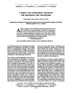
limits of canopy forests (Majasalmi et al., 2017), or in modelling of GISs for an open area (Harvey et al, 2017). Cameras are considered a non-expensive tool that can be use in capturing 3D images of an object. The advancement in imagery tools industry made techniques that reply on using cameras more and more applicable. The cameras used can be categorized into two major categories: A Time-of-Flight (ToF) which are often called depth cameras, and regular cameras that employ the structured light technology (Anderson, 2016). Structured light technology usually focuses a light (mainly LED white light) and captures the reflected light and shadows on the scanned object from different angles to provide necessary data needed to reconstruct the object (Reinhard et al., 2010). Several applications benefit from this low-cost techniques, like studying rare or poisonous plants (Nguyen et al., 2015), human skin indentation in cosmetics industries (Ares, et al., 2014), dental imaging and model reconstruction (Logozzo et al., 2014), and in cranio-maxillofacial imaging (Kantor, 2017), among so many others. The most important feature of using this technique is the speed of capturing 3D images (2 seconds for scanning and 3 to 5 for rendering, according to the FACTORYSMART® BLOG) Time-of-Flight cameras often use the Complementary metal–oxide–semiconductor (CMOS) technology in built in sensors to capture reflected wave pulses from an object to be scanned (Li, 2014), as shown in figure 1. These pulses (laser or radio or infrared) are projected on the object to be scanned, and the time required for this pulse of wave to be captured back is calculated to find the range of distance of the scanned object (with the speed of light already known).
Figure 1. ToF camera basic action (object proportions are irrelevant- drawing is for clarification only) This type of cameras is widely used in moving objects, due to its ability to fast capture depth points of scanned object. Researchers like Edgar, et al., (2016), used such camera to build high-resolution reflectivity map for sensing mobile robot from a video stream. Changing environment model building need a 3D canner that is able to cope with the changes that takes place, this is where a ToF camera system is useful, as in the work of Pogrebnyak, et al. (2016); who used it in a finding metrological possibilities to be able to build a Kinect controller of, mostly, games. After an object is scanned, reconstruction of the scanned object is needed, in a process most commonly referred to a “rendering” of surfaces, or model building. Most commonly used model building techniques use a set of images, either shot in sequence, like the construction of a building model from sequence of thermal images, as in the work of Vidas, et al., (2013), or images of the same object but from different angles, as in the work of Chen et al., (2014), who used a set of different images for a face to construct a holographic image. 3. The Scanning Robot Festo Robotino has been chosen for this project because of its easy to program user interface by using RobotinoView software. The Robot has three wheels and a built in Wireless interface with a high resolution camera mounted on it, besides having nine built-in infrared (IR) sensors for obstacle avoidance and a microcontroller system capable of capturing and processing images in real time. three ultrasonic sensors have been added to this Robot beside an I2C interface Heptagon OLIVIA 3DRanger Time of Flight (ToF) camera. When the robot is in remote area and receives an operator command to 3D scan an object. It will start 3D scan process of the object that is in front of it. The Robot starts by turning on an ultrasonic sensor to measure the distance between it and the object to be scanned. Depending on the used camera, the maximum distance allowed is 2 meters, and because the object we need to scan will have depth points inside it, Robotino will move one meter away from object. Next, ToF camera is turned on in parallel with Robotino’s built-in camera and both cameras will start to take images in sync (at the same time, they both take a frame). While taking these frames, Robotino will activate all 172
mas.ccsenet.org
Modern Applied Science
Vol. 12, No. 4; 2018
nine built-in IR sensors for obstacle avoidance just in case, and will start rotating around the object to complete the initial step of 3D scanning (taking frames from all around the object). Figures 2 and 3 show the movement of the robot around the object to be scanned.
Figure 2. Robotino path around object
Figure 3. Sketch to show Robotino movement around object Next, all these frames (from original camera and ToF camera) are sent to base station via wirelessly in order to use them for 3D reconstruction and building of a Computer Aided Design (CAD) model In order to rotate Robotino around an object, three Depth of Field (DOF) points are needed. X and Y travel in specified distance from 3D scanned object, and omega set point on Z axis is required to create circular path movement. Some 3D scanned objects may not look like an exact cylinder, thus, Robotino shall keep monitoring distance between it and the object by ultrasonic sensor. Relative orientation deviation can be checked by side ultrasonic sensors (1 and 3) shown in figure 4.
Figure 4. Cross section of Robotino showing ultrasonic sensors and camera positions with respect to scanned object 173
mas.ccsenet.org
Modern Applied Science
Vol. 12, No. 4; 2018
Heptagon OLIVIA 3DRanger has been used as a ToF (time of flight sensor) because this sensor emits IR waves and depends on their reflection time (with the speed of light taken in mind) to determine distances (depth) in every image pixel in the image. ToF has been chosen in this application because of its advantages: 1. Ability to capture the depth of each frame accurately. 2. Target texture (such as color and material) does not affect the scanned images 3. Unlike structured light scanners, ToF does not depend on time multiplexing. The subroutine that takes place at the robot’s side starts by receiving a command from the controller to start the scanning process. Once this command is received, the robot measures the distance from the object to be scanned through the readings of the ultra-sound sensors to determine the proper distance from the object to be approximately one meter away. Afterwards, the scanning procedure takes place. The scanning is done with the help of IR (Infrared) sensors that help in determining the distance of the robot from any obstacles that might get in the way, and also would help in avoiding them. Once the robot is of close enough distance (mainly one meter away) from the object and not obstacles are on the way, the cameras are turned on and the scanning process is initiated. The 3D scanning process is shown in steps in the flowchart shown in figure 5.
Figure 5. 3D scan subroutine 4. The Base Station After the base station receives all images transmitted by the Robot, it is time to reconstruct them into a 3D model. 174
mas.ccsenet.org
Modern Applied Science
Vol. 12, No. 4; 2018
This process includes: 1) Using SynthEyes (Note 1) software to make initial estimation of all scanning poses for each image depth Note: Images from built-in 1080P camera has been used, while depths where gotten from ToF camera. The reason is because ToF camera can provide us with great information about depth but it does not include high quality images. yet, because both cameras work in sync and captured frames together, the software could easily use depth information from ToF on HD camera images. This did make the texture unstable as shown in CAD model in figure 10, but the overall result has a good quality image. 2) Set of depth images are divided into segments and then to a 3D geometry using a probabilistic alignment method ready off the shelf software. Figure 6 shows the actual testing robot in action, approaching an object to be scanned.
Figure 6. Robotino in Action The results show a good image quality, but not a very high resolution of the 3D CAD object due to noise in environment and Robotino’s inability to capture images from top and bottom of object, and due to low resolution of ToF camera where its depth information were used in HD camera images to provide a better quality CAD model, but this lead to unstable texture as shown in results in figure 9. As far as we know, the proposed technique has not been used by any of the published research and applications, it is a unique algorithm applied with an omnidirectional robot, so comparisons with other existing systems cannot be done. The testing of the system is shown in sequence of steps in figures 7, 8 and 9 consequently. Where figure 7 shows the object to be scanned by robotino’s system, figure 8 shows the image segments received from the two synced cameras, and figure 9 is the reconstructed model of the scanned object using a CAD modelling tool.
Figure 7. The object to be scanned 175
mas.ccsenet.org
Modern Applied Science
Vol. 12, No. 4; 2018
Figure 8. Retrieved segments from 3D scanner
Figure 9. The reconstructed CAD model from Scanned Object 5. Conclusion and Future Work The use of a robotic system to scan objects in a remote area has proven its efficiency in multiple applications. The system that is proposed in this research is unique on its own, it uses multiple cameras; one that is dedicated for 3D scanning, and another HD camera dedicated to capture the depth of the scanned object. The captured images that are taken by synchronizing both cameras to capture the same angle are transmitted to the base station for processing and building a 3D model. The future sounds promising for such applications, and attempts to reach an optimal scanning and rendering and reconstruction of scanned objects are accelerating. The proposed technique captures high resolution, fully integrated, and diverse depth data images of the scanned object, yet the reconstruction software still needs enhancement, so future work will be taking into consideration enhancing the reconstruction of the scanned object along with filtering images before using them in reconstruction to eliminate the effect of noise. References Anderson, J. (2016). A closer look at 3D imaging: capturing the third dimension can be done in many different ways, and each of the machine vision technologies available has its pros and cons. Quality, 55(9), 18VS. Ares, M., Royo, S., Vidal, J., Campderrós, L., Panyella, D., Pérez, F., Vera, S., & Ballester, M. A. G., (2014). 3D scanning system for in-vivo imaging of human body. In Fringe 2013 (pp. 899-902). Springer, Berlin, Heidelberg. Chen, J. S., Chu, D., & Smithwick, Q. (2014). Rapid hologram generation utilizing layer-based approach and graphic rendering for realistic three-dimensional image reconstruction by angular tiling. Journal of 176
mas.ccsenet.org
Modern Applied Science
Vol. 12, No. 4; 2018
Electronic Imaging, 23(2), 23-16. Edgar, M. P., Sun, M. J., Gibson, G. M., Spalding, G. C., Phillips, D. B., & Padgett, M. J. (2016). September. Real-time 3D video utilizing a compressed sensing time-of-flight single-pixel camera. In Optical Trapping and Optical Micromanipulation XIII (Vol. 9922, p. 99221B). International Society for Optics and Photonics. FACTORYSMART® BLOG. (2017). Retrieved October 31, https://lmi3d.com/company/digital-hub/blog/cycle-times-structured-light-inspection
2017,
from
Fei, Z., Zhou, X., Gao, X., & Zhang, G. (2015). A flexible 3D laser scanning system using a robotic arm. In Optical Measurement Systems for Industrial Inspection X (Vol. 10329, p. 103294U). International Society for Optics and Photonics. Harvey, A. S., Fotopoulos, G., Hall, B., & Amolins, K. (2017). Augmenting comprehension of geological relationships by integrating 3D laser scanned hand samples within a GIS environment. Computers & Geosciences, 103, 152-163. Heinz, E, Eling, C., Wieland, M., Klingbeil, L., & Kuhlmann, H. (2015). Development, calibration and evaluation of a portable and direct georeferenced laser scanning system for kinematic 3D mapping. Journal of Applied Geodesy, 9(4), 227-243. Kantor, J. (2017). Computer generated three-dimensional modeling using passive stereo-photogrammetry and structured light scanning for cranio-maxillofacial imaging. Journal of Plastic, Reconstructive & Aesthetic Surgery. Li, L. (2014). Time-of-flight camera–an introduction. Technical white paper. (SLOA190B). Logozzo, S., Zanetti, E. M., Franceschini, G., Kilpelä, A., & Mäkynen, A. (2014). Recent advances in dental optics–Part I: 3D intraoral scanners for restorative dentistry. Optics and Lasers in Engineering, 54, 203-221. Majasalmi, T., Korhonen, L., Korpela, I., & Vauhkonen, J. (2017). Application of 3D triangulations of airborne laser scanning data to estimate boreal forest leaf area index. International Journal of Applied Earth Observation and Geo-information, 31(59), 53-62. Nguyen, T. T., Slaughter, D. C., Max, N., Maloof, J. N., & Sinha, N. (2015). Structured light-based 3D reconstruction system for plants. Sensors, 15(8), 18587-612. Paulus, S., Eichert, T., Goldbach, H. E., & Kuhlmann, H., (2014). Limits of active laser triangulation as an instrument for high precision plant imaging. Sensors, 14(2), 2489-2509. Pogrebnyak, E. M., Sedinin, V. I., & Skorobogatov, R. Y. (2016). Metrological opportunities of direct three-dimensional measurement of objects by means of the Kinect controller. In Actual Problems of Electronics Instrument Engineering (APEIE), 2016 13th International Scientific-Technical Conference; (Vol. 1, pp. 207-209). IEEE. Reinhard, E., Heidrich, W., Debevec, P., Pattanaik, S., Ward, G., & Myszkowski, K. (2010). High dynamic range imaging: acquisition, display, and image-based lighting. Morgan Kaufmann. Straub, J., Benjamin K., Atif, M., & Scott K., (2015). Characterization of a large, low-cost 3D scanner. Technologies, 3(1), 19-36. Vidas, S., Moghadam, P., & Bosse, M. (2013). 3D thermal mapping of building interiors using an RGB-D and thermal camera. In Robotics and Automation (ICRA), 2013 IEEE International Conference; (pp. 2311-2318). IEEE. Note Note 1. Demo is available online through: https://www.ssontech.com/ Copyrights Copyright for this article is retained by the author(s), with first publication rights granted to the journal. This is an open-access article distributed under the terms and conditions of the Creative Commons Attribution license (http://creativecommons.org/licenses/by/4.0/).
177