A Software Toolkit for Visualizing Enterprise Routing Design Xin Sun† , Jinliang Wei† , Sanjay G. Rao† , and Geoffrey G. Xie? of Electrical and Computer Engineering, Purdue University ? Department of Computer Science, Naval Postgraduate School {sun19, jlwei, sanjay}@purdue.edu,
[email protected]
† School
Abstract—Routing design is widely considered as one of the most challenging parts of enterprise network design. The challenges come from the typical large scale of such networks, the diverse objectives to meet through design, and a wide variety of protocols and mechanisms to choose from. As a result network operators often find it difficult to understand and troubleshoot the routing design of their networks. Furthermore, today’s common practice of focusing on one router or one protocol at a time makes it a onerous task to reason about the network-wide routing behavior. We believe that to mitigate the problem, there is a need for software tools to produce effective visualization of enterprise routing designs. In this paper we report on our experience building such a toolkit. We begin by abstracting various routing mechanisms into a small number of design primitives. The abstraction allows for a more concise representation of routing design without losing important design information, which is critical for making the tool scalable. Guided by the abstraction, we then develop a set of algorithms and heuristics, which take router configuration files as input and output a graphical representation of the routing design. The layout and components of the graph are highly customized to optimize its readability and power to infer the network-wide design pattern. We also present a case study using the toolkit to analyze the routing design of two large campus networks, and report on our findings. Our experience confirms the effectiveness of our toolkit in revealing key design characteristics of the networks, and in illustrating the network-wide routing behavior.
I. Introduction Routing design is arguably the most complex part of enterprise network design. On the one hand, routing design is often used to implement a diverse set of policies that are specified as network-wide requirements (e.g., resiliency and isolation of different administrative domains). On the other hand, routing design is implemented through configuration of a variety of protocols and mechanisms on commonly hundreds of routers. The current “device by device” and “protocol by protocol” configuration practice makes it difficult for the network operators to see and understand the network-wide routing behavior. Design faults and configuration mistakes are not uncommon in today’s enterprise networks [1], and can result in serious security vulnerabilities. For example, a recent survey [2] shows that over 65% of cyber attacks have exploited such vulnerabilities. To mitigate the problems in managing enterprise networks, We believe there is a need for software tools that can automatically create effective visualization of routing design. A
naive approach of showing every single router and all the connections among them will simply not work, due to the large scale of the enterprise networks (with typically hundreds and even thousands of routers). Furthermore, routers have different roles in the network. For example, some routers are entirely inside a single “domain”, while other routers route traffic across multiple domains. When visualizing the routing design, it is critical to give routers different treatment based on their roles, as doing so exposes the design patterns and structures. In this paper, we report on our experience in building such a toolkit. Our contributions are threefold. First, we make several significant improvements to the start-of-the-art models of enterprise routing design. In their pioneering work [3], Maltz et al. have proposed the concept of “routing instances” as an abstraction for modeling routing design. A routing instance models the set of routers that run the same routing protocol, use matching protocol parameters, and share routing information. This concept significantly facilitates the routing design visualization, as it has the power of aggregating a large number of routers into a single node on the graph. To the best of our knowledge, all prior works (for example, [3], [4]) have modeled a routing instance as a single entity, and have assumed that all routers inside a instance have the same routing information. However, in this paper we show that in operational networks, routing policies may also exist inside a routing instance, which will cause routers in the instance to have different routing information. Hence modeling routing design at the granularity of routing instances can result in loss of important design information. We further introduce the notion of filtering primitive to model route filters that implement intra-instance policies. Second, we present a set of algorithms and heuristics that can generate visualization from router configuration files using the improved model of routing design. The layout and components of the graph are highly customized to optimize its readability and power to infer the network-wide design pattern. Third, we have implemented and integrated the model and visualization algorithms into a fully-automated software toolkit. In particular, we report a case study using the toolkit to analyze the routing design of two large university campus networks. The findings, most of which have been confirmed by the operators, demonstrate the tool’s power in revealing key design characteristics of the networks. We believe our unique experience of developing this toolkit and our insight
from studying the operational networks is a contribution of its own.
routing mechanisms that are used to connect multiple routing instances. Base on their functionality, these mechanisms can be further classified into two subcategories: bridging mechanisms and injection mechanisms. Bridging mechanisms: These are the mechanisms that enable the border router of a routing instance to learn about routes to other instances, and also advertises its own routes to border routers of other instances. Depending on how the border router obtains the routes,bridging mechanisms may be further classified into (i) learning based , i.e., routes are automatically learned through a dynamic protocol such as BGP; (ii) hard-coding based, i.e., routes are hard-coded into the configuration. This includes static routes and default routes; and (iii) participation based, i.e. a router can have routes to multiple instances simply by participating in all those instances. Injection mechanisms: These are the mechanisms that enable a border router to inject the learned external routes to other routers in its routing instance, so those routers can have routes to other instances as well. A common injection mechanism is route redistribution. Another common injection mechanism is to have the border router generate a default route to its routing instance. For example, the “default-information originate” command enables a router to inject a default route into the OSPF network. We note that injection mechanisms do not have to be implemented on the border router. For example, in a small network with a single gateway router, a default route may be configured on every router that points to the gateway router. Those default routes are essentially the injection mechanism in this case.
II. A Framework for Modeling Enterprise Routing Design In this section, we present a framework for modeling enterprise routing design. While our framework leverages abstractions (e.g., routing instances) introduced by previous work [3], [4], we have made remarkable improvements. We also introduce a new abstraction of filtering primitive. The value of this framework is that it abstracts away the lowlevel configuration details without the loss of important design information, and also that it exposes the network-wide routing design patterns and structures. Below we describe in details the essential elements of the framework. A. Routing instances The logical concept of a routing instance is first introduced in [3]. A routing instance models the set of routing processes that run the same routing protocol, use matching protocol parameters, and share routing information. (A routing process runs locally on a router, and can exchange routing information with adjacent routing processes running on other routers. A router may run one or more routing processes, and form its forwarding table by aggregating routing information learned through all its processes.) The routing instance model has the power of aggregating a large number of routing processes, and exposing the complex routing policies and interactions among multiple routing protocols. However, this routing instance model has a significant insufficiency: it does not model the routing policies that exist inside a routing instance. Based on our findings in operational networks (see Section V-A1), and our discussion with network architects and operators, we believe that having policies implemented inside a routing instance is not an uncommon design pattern. More specifically, we found that route filters may be applied within a routing instance, and effectively divide the routing instance into multiple subinstances. Routing processes that are subject to the same set of route filters form a subinstance, and they share exactly the same routing information. Different subinstances, even in the same routing instance, will not share the same routing information, as some of the routes are filtered out by the route filters when they are exchanged across the subinstances. Given the this insight, we believe that it is critical to model the routing design at the granularity of routing subinstances, as doing so preserves the important policy information that exists inside a routing instance, and exposes the potentially complex interactions among the subinstances. We will present an algorithm for extracting the routing subinstances and their interactions from router configuration files in Section III-B.
C. Filtering primitive Contrary to the connecting primitive, the filtering primitive is used to prevent routing instances from sharing some routing information with other routing instances. There are also multiple types of route filters, such as distribute-list and route-map. Based on their placement, these route filters can be grouped into two categories: intra- and inter-instance filters. Intra-instance filter: These are filters that are placed within one routing instance to prevent certain routes being exchanged within the instance. Under different routing protocols, routing information is disseminated in various formats. For example, a RIP packet contains a list of (network-address, distance) pairs that the advertising router can reach, while OSPF link-state advertisements only contain information about the nodes that are directly connected to the advertising router. Despite the various formats of routing information dissemination, an intrainstance filter prevents certain routes’ distribution by dropping routing advertisement packets that contain routing information about certain networks. Inter-instance filter: These are filters that are placed between routing instances, used to prevent certain routes being redistributed from one instance to another. Depending on the configuration, they may either prevent routes’ redistribution entirely if their attributes match certain criteria, or modify the routes’ attributes and then redistribute them.
B. Connecting primitive After routing instances are established, a routing design must enable them to share routing information by using connecting primitive. This primitive abstracts a variety of 2
III. Framework Reification and Extraction
identify router interfaces and relevant attributes of each interface. Then routing process(es) running on each interface, the associated status (active or passive) along with relevant parameters are identified. An interface running n routing processes are assigned n unique tuples. 2) As [4]’s algorithm, a breadth first search (BFS) algorithm is used to explore all the neighboring interfaces to assigned each (interface, protocol, routing process id) tuple to a routing instances. However, if route filters (such as ”distribute-list”) are applied on its interface, the tuple does not participate in BFS. Instead, it is just added to the set of filtering interfaces for later use. With filtering interfaces eliminated, routing instances that employ filtering mechanisms are divided into subinstances. 3) Having all routing instances and subinstances identified, we present the following algorithm to determine route filters that are on the paths along which subinstances of one routing instance exchange routing information.
In the previous section, we propose a formulated framework that captures the core of a network’s routing design. In this section, we discuss how such an abstraction is reified in practice and present an effective procedure to extract such information router configuration files. A. Framework’s data structure and reification As a network’s connecting and filtering primitives are essentially interactions among routing instances, subinstances and other objects such as border routers and external ASes, a graph would be an applicable data structure for representing this framework, where nodes represent objects like routing instances and routers, and edges represent interactions among nodes. Possible nodes of the graphs include: (i) routing instances and subinstances; (ii) border routers between routing instances of different protocols where they share routes with one another; (iii) internal routers whose some interfaces participate in a routing protocol with route filters. Such routers form bridges that connect routing subinstances of the same protocol together; (iv) routers that route packets along configured paths, i.e. routers that have static routes; (v) peering external AS-es and border routers to which external AS-es are connected, which are needed to illustrate the network’s BGP configuration. Edges may represent the following interactions: (i) route redistribution, i.e. routing processes of different routing instances exchange routes; (ii) route filtering within the same protocol, i.e. routing processes of different routing subinstances exchange routing information through paths of route filters; (iii) eBGP peering, i.e. gateway routers run eBGP peering session with external AS-es; (iv) iBGP peering, i.e. internal routers run iBGP sessions form peering relationship; (v) hard-coded routes, i.e. static routes and default routes. The above graph practically reifies the formulated framework. First, the bridging mechanisms are reflected by interactions such as eBGP and iBGP peering for BGP route advertisement and hard-coded routes. Second, the injection mechanisms are reflected by route redistribution. The bridging mechanisms and injection mechanisms together compose the connecting primitive. The filtering primitive is shown by the route filtering interaction within a routing instance.
a) Let F denote the set of filtering interfaces, U denote the set of routing instances/subinstances resulted from last step, and U denote a routing instance in U. Let p(U ) denote the protocol that routing processes of U run. Let S denote an initially empty stack, and P denote an initially empty array. Let i(f ) denote the index of interface f . Let l(P ) denote the number of elements in P . b) If two interfaces f1 and f2 are neighboring (within the same subnet) and exchanging routing information, we say that they are connected, and denote it as connect(f1 , f2 ). c) 1: for U ∈ U do 2: for f ∈ F do 3: if ∃ fx ∈ U such that connect(fx , f ) then 4: Set i(f ) to 0; 5: Push f into S; 6: end if 7: end for 8: while S 6= ∅ do 9: Pop f out from S; 10: Remove all elements in P whose indexes are larger than i(f ); 11: Add f to the end of P ; 12: for fx ∈ F do 13: if connect(fx , f ) and fx ∈ / P then 14: Set i(fx ) to l(P ); 15: Push fx into S; 16: end if 17: for Ux ∈ U do 18: if U is of the same protocol as Ux and ∃ fx ∈ U such that connect(fx , f ) then 19: P is a filtering path through which U and Ux exchange routing information;
B. Framework extraction While most nodes and edges of the graph are directly extractable from configuration files, identifying routing instance, routing subinstances and the filtering mechanism inside each routing instance requires significant processing. Paper [4] presented an effective procedure for extracting routing instances from configuration files. However, that paper treats a routing instance as a single unity in its modeling, and do not consider the filtering mechanism inside each routing instance. Here we present a modified procedure to identify routing instances, subinstances along route filters that are in the path along which two routing subinstances exchange routing information under the same protocol. 1) As stated in [4], the configuration file is parsed to 3
represents that a static (default) route is configured on A, which uses B as the next-hop. An edge between a router and a routing instance (or subinstance) represents that the router participates in that routing instance(or subinstance). Such an edge may be labeled with the names of other routing instances that the router also participates, to show that the router redistributes routes from those instances into this instance. Similarly, an edge may also be labeled with “static” to denote that the router redistributes its static routes into the instance. What’s more, at the router end of such an edge, a short line across it represents that a route filter is configured on the router, which regulates the routes exchanged between the router and the rest of the routing instance (or subinstance). Finally, black arrows between two routers represent the iBGP peering sessions established between them. A black arrow from a router to an AS denotes an eBGP peering session established between the router and the external AS. (This makes the router a gateway router of the network.)
end if end for 22: end for 23: end while 24: end for 4) After applying the above algorithm, we find all routing instances and their subinstances if exist, along with route filters that are in the path along which two subinstances of the same instance exchange routing information. 20: 21:
IV. Framework Visualization In this section, we present the procedure to visualize the extracted framework, and a set of techniques that optimize the generated graph for human-readability. In visualizing the framework, our objectives are: (i) the generated graph should present a concise overview of the network’s routing design, along with moderate details about its key aspects which may provide clues for trouble-shooting; (ii) the generated graph must be human-readable, which implies that information should be appropriately trimmed; (iii) the graph generation process must be fully automated while customized fine tuning should still be allowed for various needs.
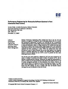
B. Graph optimization Simply feeding the nodes and edges into GraphViz, the generated graph is as Fig.1. As we have seen, the graph is a too chaotic for user to read. Problems of this graph include: (i) arbitrary node placement; (ii) crossing and overlapping edges; (iii) large amount of nodes; (iv) large amount of text labels. Here we present a set of graph optimization techniques for better visual effects.
A. Graph generation The formulated framework itself is already a concise representation and visualizing it would fulfill the requirement for a concise graph. A generic graph visualization tool, GraphViz, is used to help generate such graphs. GraphViz is chosen for several reasons. First, GraphViz implements a set of algorithms to optimize the placement of nodes and edges to optimize visual effects. Second, GraphViz allows enough flexibility for us to further optimize the graph knowing the network’s semantic structure. Third, GraphViz supports a wide range of node and edge shapes and colors, which makes it possible for representing information using the graph itself without the need for too much text. Our toolkit generates a GraphViz dot file and passes it to GraphViz to generate the graph. Next we describe how the generated graph represents the network routing design. The generated graph may have three types of nodes: routing instance or routing subinstances, routers and AS-es. Routing instances’ names have the format of “protocol-ID” (e.g., OSPF-1), where protocol is the protocol that the routing instance is running and ID is the process ID of routing processes in this instance, or AS number if the protocol is BGP. Routing subinstances are placed inside the routing instances that they belong to. Names of routing subinstances are in the format of “protocol-ID-subID” (e.g., EIGRP-1-2), where the subID is the ID within the routing instance to distinguish the routing subinstance from other subinstances. Routing instances’ or subinstances’ names are also followed by the number of routers in the instance or subinstance. The router name may be suffixed by a star, which means that the router is configured with a default route or a default gateway. AS-es’ names are in the format of ”AS-number”, where number is the corresponding AS number. A green (red) arrow from a router A to another router B
1) Planned node placement To better show the hierarchy of the graph, we place all routing instances on the top of the graph, routers in the middle, and AS-es at the bottom. 2) Distinguishing different node types Nodes for routing instances, routers and AS-es are drawn in different shapes for differentiation. As on our graph, we use diamond nodes for routers, rectangular nodes for routing instances and subinstances, and elliptical nodes for AS-es. 3) Clustering functionally equivalent nodes Since the most important role peering AS-es play is providing connection to Internet for the network, operators of the network would only be interested in what gateway routers an AS is connected to. So we consider AS-es are functionally equivalent if they connect to the same border routers. We cluster the functionally equivalent AS-es together as one node to minimize the number of AS nodes. Routers are considered functionally equivalent if they play the same role, such as redistributing routes for the same routing instance or subinstance, or constituting alternative filtering paths for routing subinstances of the same instance. Functionally equivalent routers are given the same color. 4) Minimizing label text Edges between routers and routing instances or subinstances are labeled with the types of routes that are redistributed into the routing instance. Since it is usually the case that the 4
router- J*
router-I*
bgp-Y
rotuer- G*
bgp-Y
bgp-Y (2)
AS-Z
router-D*
ospf-2 (6)
eigrp-1
static
router-H*
bgp-Z
eigrp-1
AS-E
bgp-Z (2)
AS-A
router-B*
bgp-Z
AS-D
AS-B
eigrp-1
AS-C
eigrp-1 (99(
eigrp-1
ospf-1-2 (1)
router-F*
ospf-1-1
eigrp-1
ospf-1-1 (1)
Fig. 1: Unoptimized graph for university-1 network’s routing design in 2011 - Note that we have manually manipulated the routing processes’ IDs, AS-es’s numbers and routers’ names on all graphs to hide confidential information. campus routing design before and after the redesign.
router redistributes routes from all other routing instances, it is unnecessary to print all other instances’ names in the label. So if that is really the case, we simply omit all other routing instances’ names. To distinguish the case that no route is redistributed, a dashed edge is used instead of a solid one in this case. Also, edges between routers and routing instances are drawn in blue to distinguish them from other edges. Effectiveness of the optimization techniques: for the same network as shown in Fig.1, our optimization techniques were able to reduce the number of nodes in the resulted graph (Fig.3) from 19 to 16, reduce the number of edges from 32 to 29, and reduce the number of labels from 11 to 1. Overall, the graph after the optimization is much more readable.
1) The 2008 design Fig.2 illustrates the routing design of University-1’s network in 2008. The graph was automatically generated by our toolkit. We have double-checked the router configuration files, and have also confirmed with University-1’s operators that the graph depicts the routing design correctly. Fig.2 shows that the network has seven routing instances, EIGRP-1, two OSPF-1 (more on this later), OSPF-2, OSPF-3, RIP, and BGP-Z. All the routers shown are border routers that route traffic across routing instances. In particular, routers C, E and F are the gateway routers that run eBGP with external AS-es; and the rest routers are internal border routers that perform mutual route redistribution between the IGP instances. We make several observations of this routing design. First, the routers in the EIGRP-1 routing instance can be grouped into two subinstances EIGRP-1-1 and EIGRP-1-2. The border router G is the only router that connects the two subinstances, so any route that is exchanged by the two subinstances must go through router G. A route filter (denoted by a short line crossing the edge in the graph) is placed on the interface of router G that faces the subinstance EIGRP-11, This filter prevents the two subinstances from exchanging certain routes. Further investigation reveals that, the routes that are filtered out by that route filter are the routes of the external AS-D. The routing design works in the following way. First, the gateway router E runs an eBGP peering session with the AS-D. It also performs mutual route redistribution between BGP and EIGRP. Note that the router E only connects to the EIGRP-1-2 half of the EIGRP instance, as shown in Fig.2. Second, all routers in the subinstance EIGRP-1-2 learns those external routes of AS-D injected by E. Third, when the subinstance EIGRP-1-2 sends those external routes through the router G to EIGRP1-1 as per the normal EIGRP protocol operation, the routes are filtered out by the route filter on G. Hence the subinstance
V. Case Study of Routing Designs in Operational Networks We have had the opportunity to use our toolkit to study the routing design of two large campus networks. Our toolkit took only a few seconds to generate each graph. In this section, we report on our experience and findings from the study. Overall, our experience confirms the usefulness of our toolkit in revealing the network-wide routing design patterns and structures. Our findings include discovery of some important design pattern that, to the best of our knowledge, has not been exposed to the research community before. A. University-1’s network routing design University-1 has a large campus with nearly 40,000 students. Its campus network is composed of hundreds of subnets. It contains about 120 routers (most of which are actually layer3 switches) and more than 1000 layer-2 switches and bridges. We have a longitudinal data-set of the configuration snapshots of University-1’s network from 2008 to 2011. Interestingly, University-1’s network has been significantly redesigned during this time period. So in this case study, we have selected snapshots from both 2008 and 2011 as they represent the 5
rip (1)
ospf-1 (1)
router-A
router-B*
bgp-Z (3)
eigrp-1-1 (94)
router-F*
eigrp-1-2 (6)
ospf-2 (1)
ospf-1 (1)
router-E
router-G*
router-D*
router-C*
AS-B AS-A
AS-D
AS-C
Fig. 2: University-1’s network routing design in 2008 bgp-Y (2)
ospf-2 (6)
eigrp-1 (99)
router-J*
static
ospf-1 (1)
router-B*
ospf-1 (1)
bgp-Z (2)
router-D*
router-G*
rotuer-E*
router-C*
router-F*
AS-E AS-A AS-Z
AS-B AS-D AS-C
Fig. 3: University-1’s network routing design in 2011 EIGRP-1-1 will never know about those routes of AS-D. (Note that the two subinstances can still exchange the EIGRP internal routes, which are not affected by the route filter.)
A users to the AS-D, and placed the route filter to prevent it from exposing the routes to the subinstance of type-B users. This interesting example illustrates the usage of routing subinstances in operational networks, and highlights the need of modeling routing design at the granularity of subinstances rather than instances to preserve important policy information.
From Fig.2, we can infer the rationale behind the routing design as follows. There exist two different types of users in the EIGRP routing instance. By the university policy, users of Type-A should be able to reach the external AS-D, whereas users of type-B must not. In order to meet this policy, the operators created the two subinstances to contain the two types of users respectively, connected the subinstance of type-
Second, the router G also performs mutual redistribution between the EIGRP-1 and the OSPF-2 routing instances. Note that there is no route filter installed on the redistribution path that will prevent router G from redistributing those routes of 6
AS-D to the OSPF-2 instance. Indeed, we are able to confirm that users in the OSPF-2 instance were all type-A users which is allowed to reach AS-D. Third, we note that in Fig.2, there are two OSPF-1 instances that look identical: they are configured with the same OSPF process ID, and connect to the same other instances. consultation with the operators reveals that there is actually just one such routing instance, but our data-set is missing the configuration files of a few routers which all located in OSPF-1. Those routers are from a different vendor and do not understand the command we use to dump the configuration snapshot. Without those routers, OSPF-1 would have been partitioned the way as shown in the graph. This incident confirms the correctness of our toolkit.
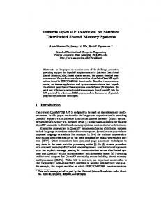
of RIP routing instances. This network has 12 separate RIP routing instances and 1 OSPF-1 routing instance. Between each RIP routing instance and the OSPF-1 routing instance, there is a border router that performs bidirectional redistribution between them. In this way, the entire network was connected together. A large number of routing instances of the same protocol may look awkward at the first place. As we only have a small subset of the network’s routers, it is questionable whether the network really have so many distinct RIP regions, or it has only one RIP instance and graph is incorrect because of lacking configuration files of routers that connect the separate RIP instances together. Our analysis predict that those are indeed isolated RIP regions. As there is a gateway router between each RIP instance and the OSPF-1 routing instance, if the RIP instances are indeed one single RIP instance, there would be at least 12 gateway routers connecting the RIP instance to the OSPF-1 instance, which is not only very redundant and wasteful, but also error-prone. Also, as further investigation suggests, dividing the network into 12 separate RIP regions and connecting them with one OSPF-1 instance turn out to be a good pattern.
2) The 2011 design Fig.3 depicts the routing design of the same university in 2011. It can be seen very clearly that the network has changed significantly from the 2008 snapshot. In the new design, there are six routing instances: EIGRP-1, two OSPF-1 (same explanation applies), OSPF-2, BGP-Y, and BGP-Z. We discuss some major design changes from 2008 below. The first major change is that there is no subinstance in the EIGRP-1 routing instance anymore. Investigation reveals that (i) the EIGRP-1 instance in 2011 is the same as the old EIGRP-1-1 subinstance in 2008, and (ii) the old EIGRP-1-2 subinstance has merged with the old OSPF-2 routing instance, and becomes the new OSPF-2 routing instance. The result of this redesign is that, now the EIGRP-1 instance contains entirely the users of Type-B, and the OSPF-2 instance contains entirely the users of Type-A. This is a cleaner design: it does not require the use of route filters inside the EIGRP-1 instance, nor does it require that the EIGRP-1 instance maintains the special star-like topology as in 2008. The second change to be noticed is the disappearance of the RIP instance. Consultation with the operators reveals that the original RIP instance was the network of a large college, which was operated independently by a separate IT team back in 2008, who happened to choose to run RIP in their network. In 2011, the university central IT team has taken over the operation of this network, and has subsequently merged it into the EIGRP-1 instance for simplified operation. (The EIGRP-1 instance is the main data network of the university and has always been operated by the university central IT.)
One key issue in network routing design is scalability. Limitation of routing protocols restricts the size of the network. For example, RIP requires that any two hosts can only be at most 15 hops away. Limited resources of routers would also prefer small networks. One common practice to achieve scalability is dividing the network into several routing zones, each of which runs a routing protocol independently, and a routing protocol running on border routers of each zone connects all zones together. As we have known, University-2 has a large campus. If it were only to run a small number of routing instances, it would need highly sophisticated routing protocols, and subsequently, it would need a large number of high-quality routers and great effort to configure them for advanced protocols. Alternatively, University-2’s network intensively utilize the idea of zone division to achieve scalability. The network is divided into 12 zones (or more), each of which run a RIP protocol, and the OSPF instance sits in the center of the network and connected all RIP zones together. After dividing the network into 12 zones, each zone is small enough. Within each small zone, a simple routing protocol like RIP will satisfy the need. And the simple protocol only requires minimal router power and is easy to configure. To connect the 12 separate zones together, an advanced protocol should be run in the center of the network. However, it only needs to run on a few routers within each zone (in University-2, one router for each zone). In this way, same or even better performance could be achieved with much less money and configuration effort.
B. University-2’s network routing design University-2 has a large campus as well, with more than 40,000 students. Its campus network is roughly of the same size as University-1’s. Unfortunately, we were only able to get 15 routers’ configuration files in 2009, which are only a small subset of its network. However, after we analyze those configuration files, these routers turn out to play important roles in the network and the generated graph still exposes important features of the network design. University-2 network’s generated graph is given in Fig. 4. What’s most impressive about this graph is the large number
Comparing the graphs for University-1 and University-2, we can see that both University-1 and University-2 divided their networks into multiple routing instances. However University1 divided its network based on functionality, while University2 divided its network based on geographical location. 7
rip (1)
rip (1)
ospf-1
bgp-X (4)
rip (1)
ospf-1
router-A*
rip (1)
rip
router-I
ospf-1
rip (1)
rip (1)
ospf-1 (12)
rip (1)
rip (1)
rip (1)
rip (1)
rip (1)
router-L*
router-D*
router-B*
rip (1)
rip
router-C*
router-E*
router-K
rip
router-J*
router-F
rip
ospf-1
router-M*
router-G*
AS-X
Fig. 4: University-2’s network routing design in 2009
VI. Related Work and Conclusion
configuration. We expect this feature to be very useful in assisting operators to trouble-shoot their networks.
Among all related work, three studies of network routing design [3], [4], [5] are most relevant. [3] proposed the model of routing instances, and used it to reverse engineer the routing design from operational networks. [4], [5] developed models for understanding the connecting primitives. Our work improves these models in three important aspects. First, all prior studies treat a routing instance as a monolithic group of routers implementing a uniform set of routing policies, and do not consider policies within a routing instance. By contrast, we show that such policies are found in operational enterprise networks, and that ignoring them in the model can result in loss of important design information. Further, we have presented an algorithm for extracting those policies. Second, one primary focus of this paper is to develop a framework for automatic visualization of routing design in a human-friendly and scalable way. To the best of our knowledge, no prior work considered automatic visualization of routing design. Finally, we have implemented a software prototype based on the framework. and used the prototype to study several operational networks. Our own previous work [6] presented a tool for visualizing and troubleshoot enterprise VLAN design. Previous work [7] presented a tool for querying reachability control, focusing on packet filters. By contrast, this work focuses on the visualization of routing design. We are currently preparing the initial release of our toolkit. In the future, we plan to enhance our toolkit to provide an interactive user interface, which will allow users to dynamically “zoom in” to part of the graph, and get in-depth information about that specific part. For example, the user would be able to zoom in to a particular routing instance and see the list of routers in that instance; and then she can continue to zoom in to a particular router in that list and check its interface
Acknowledgment This work was supported by NSF grants Career-0953622, CNS-0721488 and CNS-0721574, and a research grant from Cisco.
References [1] Z. Kerravala, “Configuration management delivers business resiliency,” The Yankee Group, Nov. 2002. [2] S. Narain, “Network configuration management via model finding,” in Proc. LISA Conference, 2005. [3] D. Maltz, G. Xie, J. Zhan, H. Zhang, G. Hjalmtysson, and A. Greenberg, “Routing design in operational networks: A look from the inside,” in Proc. ACM SIGCOMM, 2004. [4] F. Le, G. G. Xie, D. Pei, J. Wang, and H. Zhang, “Shedding light on the glue logic of the internet routing architecture,” in Proc. ACM SIGCOMM, 2008. [5] F. Le, G. G. Xie, and H. Zhang, “Understanding route redistribution,” in Proc. International Conference on Network Protocols, 2007. [6] S. Krothapalli, X. Sun, Y.-W. Sung, S. A. Yeo, and S. Rao, “A toolkit for automating and visualizing vlan configuration,” in Proc. NSF SAFECONFIG Workshop, 2009. [7] A. R. Khakpour and A. X. Liu, “Quantifying and querying network reachability,” in Proc. IEEE ICDCS, 2010.
8