Abstract: A three level control system for a variable speed wind energy conversion scheme (VSWECS) supplying a weak AC sys- tem is presented. The objective ...
IEEE Transactions on Energy Conversion, Vol. 14, NO. 1, March 1999
122
A VARIABLE SPEED WIND ENERGY CONVERSION SCHEME FOR CONNECTION TO WEAK AC SYSTEMS A.S.Neris, Non member, IEEE N.A. VOVOS, Senior Member, IEEE G.B Giannakopoulos, Senior Member, IEEE Department of Electrical and Computer Engineering University of Patras 26500 Rion, Greece Abstract: A three level control system for a variable speed wind energy conversion scheme (VSWECS) supplying a weak AC system is presented. The objective of the control strategy is to maximize energy capture and simultaneously to support the voltage of the bus where the VSWECS is connected. Using an insulated gate bipolar transistors (IGBT) inverter both control of active and reactive power supplied to the grid and reduction of harmonic distortion can be achieved. The response of the proposed scheme has been tested and evaluated in a test system using a developed computer program simulating in detail the system operation. Keywords: Wind power, fixed-pitch, variable speed, converter, autonomous power systems, harmonics.
I. INTRODUCTION World wide variable speed wind turbines (WT) are outnumbered by fixed speed WT. One main reason is that variable speed implies a conversion step from mechanical energy at variable speed to electric energy of constant frequency. This conversion, mainly for economical reasons, is usually realized by power electronic converters, which introduce harmonic distortion to the voltage waveform. The recent advent of inverters using the insulated gate bipolar transistors (IGBT) looks as a promising solution to the above mentioned problem [1,2]. IGBT prices are decreased and their available maximum power rating is increased both about 30% per year. Today six-pulse inverters using IGBT able to handle power in the range of 1 MVA with a switching frequency about 5 to 10 KHz are available. These inverters, using pulse width modulation (PWM) techniques, eliminate the low frequency harmonics and the first harmonics appear around the switching frequency of the inverter. Therefore, by overcoming the basic problem of VSWECS with a logical cost, their use can offer a number of important advantages such as increase of energy capture, reduction of fatigue damage on rotor blades and drive train, reduction of aerodynamic acoustic noise level and improvement in operational flexibility.
In the application field, hybrid weak autonomous power systems including WT and diesel or small steam or gas generators represent, economically, an interesting alternative for remote communities with good wind conditions, as the Aegean sea islands in Greece. However, there is a reluctance to connect WT to such weak AC systems, mainly because of the uncertainty with respect to the reliability and the maintenance cost of WT, but also because of the poor power quality due to the rapidly fluctuating wind power which causes voltage and frequency deviations in the output of the WT. In this paper a VSWECS is proposed employing a control strategy for the advanced IGBT inverter used, which not only increases the efficiency of the WT operation but also can both control simultaneously the active and reactive power [3] and reduce the harmonic distortion in the output of the system. These characteristics improve the power quality supplied by the VSWECS and therefore, remove a basic barrier to the connection of VSWECS to weak AC systems [4,5]. The operation of the proposed VSWECS and the efficiency of the control strategy are demonstrated and tested in a small system using simulation techniques. 11. DESCRIPTION OF THE VSWECS
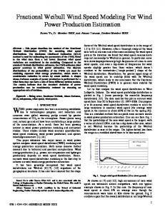
The proposed VSWECS is shown in Fig. 1. It uses a fixed-pitch stall regulated type WT. This WT is preferred to a controlled pitch type for its increased reliability, reduced maintenance and low cost but also because part of the controlled pitch job is replaced by the proposed electrical system of the VSWECS. The WT drives a self excited brushless synchronous generator (SG) with automatic voltage regulator (AVR). The SG supplies power to a diode rectifier chosen for its simplicity, low cost and low losses. The use of the diode rectifier is possible since the voltage control of the DC link is achieved through the AVR of the SG. The rectifier generates non sinusoidal generator currents which increase the genera I
PE-91 1-EC-0-10-1997 A paper recommended and approved by the IEEE Energy Development and Power Generation Committee of the IEEE Power Engineering Society for publication in the IEEE Transactions on Energy Conversion. Manuscript submitted December 31,1996; made available for printing October 21,1997. rectifier
inverter
Fig. 1. The proposed VSWECS.
0885-8969/99/$10.00 0 1997 IEEE
123
tor losses and decrease the rating of the generator by about 5%. Also the commutation of the diodes leads to a voltage drop of about 5 to 10%. The DC inductor is used to smooth the ripple of the direct current. The IGBT inverter controls the active and reactive power of the VSWECS supplied to the grid. The small grid filter is used to eliminate the high order harmonics. 111. THE CONTROL STRATEGY
put V,,Vb and V, are transformed into the d-q plane using the following equations : Vd =2(Va -0.5Vb -0.5Vc)/3 The time integral of the above voltage space vector is called "flux vector" Y., and its d-q axis components are calculated by the equations : f
Yd.,= h d d t and The control system objectives are the following : 1) Control of the active power supplied by the VSWECS to the grid. Below rated wind speed, this power is regulated to be equal to the maximum wind energy captured by driving the WT to operate at peak power coefficient C,. Above rated wind speed the WT is stall regulated. 2) Control of the reactive power interchange between inverter and grid in order to keep constant the AC bus voltage of the inverter. 3) Utilization of the P W M technique to achieve substantial harmonic reduction. 4) Control of the SG output voltage to regulate the direct current for stable operation of the DC link. 5) Robustness, i.e the controller should give adequate performance for all operating points in which it is active. The first three objectives are realized by using the appropriate switching procedure of the IGBT valves of the inverter, which is determined by the lower level of the control system and requires set points for the voltage and the real power to operate. These two set points are specified by the intermediate control level. The upper level of the control system secures the stable operation of the DC link. A . Lower level of the control system
The real and reactive power P and Q fed by the inverter into the AC system are controlled by a method that controls the time integral of the inverter output voltage space vector. This method has previously been applied to AC motor drives [ 6 ] . Fig.:! shows the structure of the lower level controller. The control uses variables transformed into the stationary d-q reference frame and is actually a vector control. The d-axis coincides with the phase a of the inverter output. In this controller the instantaneous AC bus voltages of the inverter out-
-
-
-U
I
(1)
vq=(V, -V,)/45
-m
Yqv=
1
Vqdt
The magnitude Y, of the flux vector is controlled so that its deviation from a set point Y p f to be within the limits of AY,, i.e : Y7f - AY., I21 Y, IYFf f AYvI2 (3 1 The set point for the magnitude of the flux vector is specified by the magnitude of the reference voltage Vref using the equation :
v rcf
yrf =- mo
(4)
where coo is the angular velocity of the reference voltage. Control of the flux vector has been shown to have good dynamic and steady state performance [ 6 ] . Also there is no discontinuity in the inverter flux vector, whereas the inverter voltage vector switches position in the d-q plane, as it is shown in Fig.3a, for the eight combinations of the status of the switches S,,S, and S , shown in Fig. 3b. The inverter voltage vector is specified by the equation : v(s1,s2,s3)=2vdc(sl -0.5s2 -0.%3)/3+ j v d c ( s z - s3)/& (5) Two combinations of the switching modes, (O,O,O) and (I,], I), give zero voltage vectors and the other six give nonzero voltage vectors. When the output is one of the nonzero vectors, Y, moves at a constant velocity which is proportional to the output voltage. Therefore, by selecting the appropriate voltage vectors, Y,, can be kept constant. The selection depends not only on the amplitude error but also on the angle 6, of Y.,. Therefore, for the specification of the appropriate voltage vector, the d-q plane is divided into six sectors according to the relation: (2n - 3 ) n/6 I e(n) 5 (2n - 1) d 6 (6) where n = I , ... 6. Table I gives the selected vectors for each sector.
I Logcal hction calculator
U Fig. 2. Lower level control scheme.
(2)
-a
Fig. 3. (a) Instantaneous voltage vector. (b) Schematic diagram of the inverter.
e(2)
SECTOR e(i) Increase V(1,l.O) Yv Decrease V(O,I,O)
Applying (9) to the switching procedure of the inverter a PWM voltage waveform is obtained at the inverter output.
V(0,l.O)
e(3) V(O.l.1)
e(4) V(O,O,l)
e(5) V(l,O,l)
O(6) V(I,O,O)
V(O,l,l)
V(O,O,l)
V(l,O,l)
V(l,O,O)
V(1,l.O)
B. Intermediate control level
YV
The angular velocity of Yvand, therefore, the power angle and the active power supplied by the inverter can be controlled by using both zero and nonzero vectors. The active power is increased by using anyone of the nonzero vectors and is decreased by using the zero vectors. The selection of the switching vector is made to satisfy the limits: Pref -AP < P < Pref +AP (7) In order to digitalize the status of the Y, and P errors given by (3) and (7), we use the logical variables cp and p which are specified by the equations :
if' : '3' - Y V 2 AYv/2 then p =I if Y,"f - Y v 5 -AYv I 2 then p =O if p r d - P > A P then p=1 if Pre' - P 10 then p =O Summarizing the previous analysis, the optimum switching table for voltage and real power control, as it is stated in [6], is given in Table 11, where the sector 8(n) of Y , is specified by the value of 6,. In order to express the Table I1 in a form of logical functions, we specify the different sectors with the 3 bit word 010203 as it is shown in Table 111. Combining Tables I1 and 111, the "truth table" which specifies the status of the switches S,,S2 and S, from cp,p and 010203 is constructed. Simplifying using Kamaugh tables, the logical functions that specify the status of the inverter switches are the following : - - - SI = +
1 pxRs CP W ,3 P,, = 2 /I3 where C, is the power coefficient, h=w,R/v, is the tip-speed ratio, R is the rotor plane radius, p is the air density and v, is the wind speed. From the rotor efficiency curve C,(h), there is a hop'where the C, is maximum, i.e Cp" =C,(hop'). Therefore, to make an optimal use of the available wind power, it is necessary to change the speed of the turbine in proportional to the wind speed in order to always keep h=hoP'.Substituting Cp" and h o p t into (1 0) we obtain : ~
1 Pax P,"" = -- pnRS %U,' = Kw: 2 ('lop[ 1 where K is a constant for a specific WT.
(1 1)
For a measured w, the Pefis obtained by the equation :
Pref = n(w,)ndPzax= n(w,.)ndKc$ (12) where n(wJ is the efficiency of the generator and gear-box as function of the rotor angular speed and nd is the efficiency of the DC link. Fig.4 shows the mechanical power- rotor angular speed curves for two different wind speeds and is used to explain the iterative procedure followed in the intermediate controller. The dashed line represents the Pref given by (12). We suppose that A is the initial operating point of the system and a step increase of the wind speed from v,, to vw2takes place.
0 2 0 3 ~ ~ 0 ~ 0 2 0 3 ~ 0 ~ ~ ~ + 0 ~ 0 3 ~ + 0 ~ 0 ~ 0 3 ~ + 0 ~ 0 3 ~ )
-
-
0,0, p + 0103pp ~
sl
This control level specifies the reference voltage magnitude Vrefand the active power Prcfused in the lower control level. For our purpose the V'"' is constant and equal to the nominal AC grid voltage. The Prefis specified in order to extract the VSWECS maximum power from the available wind energy for wind speed below rated. An iterative procedure is proposed to reach the system the optimum use of the available wind power measuring only the rotor angular speed w, and avoiding the direct measurement of the uncertain wind speed experienced by the WT. The mechanical power obtained from the wind is given by the following equation :
.
-
-
0 3 p+@1@2 0 3
-
-
- -
pp+@I0 2 p + 01pp+ 010 3
(9)
TABLE 11
SWITCHING TABLE FOR VOLTAGE AND REAL POWER CONTROL
Fig. 4. Mechanical power-rotor angular speed curves for constant wind speeds.
125
Under these conditions the extracted power is PA, but since the available power is P, there is an accelerating power P,PA that will increase w,. The new orspecifies now the new P"', that corresponds to, let say, point C, but still there is an accelerating power. This power increases even more w, and specifies a new greater Pref. This procedure is repetitively continued until the new stable operating point D is reached. Small oscillations around the new operating point are expected. Aerodynamically the curve C,(h) is not entirely constant for all rotor speeds and therefore K in (1 1) can be a function of w,for a specific WT. At high wind speeds, when the rated power of the WT is exceeded, the intermediate control is overridden by a control system for stall regulation at constant power (equal to rated power). More detailed study of this control system will follow in a future work. For autonomous small systems where the VSWECS must also contribute to the frequency control under specific conditions, the maximum wind capture control can be inactive and P"' can be specified by a frequency droop characteristics controller [3].
Fig.6. Site of the WT used in the test system (Drepanon. Achaia, Greece)
units. It consists of a 30 KW, fixed pitch, horizontal axis, upwind WT, with three blades 6m long, rated speed 74 rpm and active yaw system which drives a 50 KVA rated SG.Detailed data of the system are given in [7] where also details are given for the representation of wind, wind shear, mechanical and electric system and for a three phase simulation method used for predicting the dynamic response of the system. In this preliminary study, the parameters and compoC. Upper control level nents of the proposed electric system are not optimized since the primary purpose of the paper is to investigate the general In this control level the reference voltage 'v : of the performance of the system before the detailed design process AVR of the SG is regulated to secure the stable operation of has been accomplished. The DC link inductor and capacitor the DC link. The desired direct current is calculated from Pref were taken 0.1H and 100pF respectively and the small single and the measured DC link voltage V,, using the equation: high- pass damped filter in the AC system is just used to conform the current distortion to the IEC 1000-2-2 standards. IZf = p'"f /V& (13) The switching frequency of the inverter was taken 10 Khz. The Igf is smoothed out by filtering and is compared to the measured current Idc.API controller specifies the AV ': from V. EVALUATION OF THE SYSTEM PERFORMANCE the following equation : Using the simulation program developed, the response of the system is evaluated for two characteristic disturbances. One is a step increase and then a step decrease of the wind speed V'ef = y o +AVref R ref g and the other is a step load change corresponding to the shutwhere VLf is the nominal reference voltage of the AVR. down of both the desalination units with the wind speed constant. The load has three power levels of operation correIV . TEST SYSTEM DESCRIPTION sponding to individual or simultaneous operation of the reThe proposed electric system of the VSWECS and the verse osmosis desalination units. The plotted quantities have been selected to present the general performance of the procontrol strategy described were studied by simulation to be posed VSWECS and the power quality delivered to the load. used for future connection of an existing WT to a local weak Fig. 7 shows the response of the system after a step inAC system resulting in the test system shown in Fig.5 . Up to crease of the turbulent wind speed from 9.4m/s to 10.45 m/s now this WT, shown in Fig. 6 , operates as autonomous sys(Fig. 7a) followed after 13 sec by a step decrease to 8.4mls. tem and is used to supply two reverse osmosis desalination This change of the wind speed results in a step increase of the WT shaft power P, (Fig. 7b) which creates an accelerating power since the delivered electric power is still constant (Fig. 7c). This causes the rotor to accelerate to a higher speed (Fig. 7d) and the resulting new Prefincreases the power output of the inverter Pin"(Fig. 7c). The intermediate control system drives the VSWECS to capture maximum wind energy in 10 sec. Fig. 7d shows a subcritical, stable but rather slow response. If the acceleration of the response with aggravation Fig.5. Configuration of the test system.
~
126
of the oscillations is acceptable, then a controllable delay can be introduced to the loop specifying Proffrom a,.The difference between P, and Pin, expresses the total losses of the VSWECS, mainly in the inverter, which are about 15%. Figs 7e-7h are presented to prove the good power quality. Yvis almost constant (Fig. 7e) which proves that the voltage is constant in the output of the inverter even under transient conditions.Fig. 7h is a spectral representation of the individual harmonic distortion of the current as finction of the harmonic order. The harmonic content is inside the acceptable limits. The total harmonic distortion for the voltage and current of the load for different power levels are given in Table IV. A similar explanation of the response is also true and when the step wind decrease takes place.
Power (KW)
Voltage THD (%)
CurrentTHD(%)
5.74 5.84 6.05
15 20 30
2.09 2.18 2.32
Fig. 8 shows the response of the system when the 20 KW local load is rejected and only some auxiliary loads of 0.5 KW remain. Figs 8a,8b and 8c show the voltage of the load bus, the real power and the current of the load respectively. Only a small transient overvoltage appears at the load bus voltage for a short period of time. The VSWECS continues to supply the same active power to the inverter output in spite
161 l"1
0.5 I
0
I
10 time (s)
5
(a)
0.0
I
1
15
20
1 /
I
I
I
I
0
5
10
15
20
h
5
s s
8 W
g
200
o -200
+l "
0
I
I
I
I
I
5
IO
15
20
(b)
-400'
time (msec)
(f)
time (s)
60 h
501 25
5 *
30
5
0
E
U
g
cl
O (
I
I
I
I
0
5
10
15
20
-30 -60
time (msec)
time (s)
r 80
i
I
0
5
(d)
:
\ I
I
1
10
15
20
time (s)
*
E
:
U
0.00
0
10
(h) Fig.7. Response of the system in a step wind change.
20
Harmonic order
30
40
127 400 1
VI. CONCLUSIONS
h
p2
200
-$
A VSWECS including SG, diode rectifier, IGBT inverter and a three level control system is proposed for connection to weak AC systems. The performance of the system has been found satisfactory in a step change of wind speed and load using a detailed non linear simulation program.' The capture of maximum wind energy is achieved with constant voltage and acceptable power quality at the inverter output. The maximum wind power tracking is achieved without measurement of the uncertain wind speed. The capability of the VSWECS to support the AC bus voltage of the inverter permits its connection to weak AC systems. The total harmonic distortion at the local bus is within acceptable levels.
c
0
3 a -200
. . . - - - . . ,..... -
-4OOJ
-
(a)
301
VI1. REFERENCES 50
0
I
I
I
1
100
150
200
250
[I]
time (msec) 121
LPierik, A.Veltman, S. De Haan, GSmith, Ohfield, and ASimmons, "A new class of converters for variable speed wind turbines" , Proceedings of the 1994 European Wind Energy Association Conference, pp. 534-540. O.Carlson, A.Grauers, JSvensson, and A.Larsson, "A comparison between elecrical systems for variable speed operation of wind turbines Proceedings of the 1994 European Wind Energy Association Conference,pp. 500-505. M.Chandorkar, D.Divan, and R.Adapa, "Control of parallel connected inverters in standalone ac supply systems", IEEE Trans. Industry Applications, Vo1.29, no.], JanuaryFebruary 1993, pp. 136-143. R. Hilloowala, and ASharaf, "A rule-based fuzzy logic controller for a PWM inverter in a stand alone wind energy conversion scheme", IEEE Trans. Industry Applications, Vo1.32, no. I, Jan./Feb. 1996, pp.57-65. T.Thiringer. and J.Linders, "Control by variable rotor speed of a fixed pitch wind turbine operating in a wide speed range", lEEE Trans. Energy Conversion, Vo1.8, no.3, September 1993, pp.520-526. I.Takahashi, and T.Nogushi, "A new quick-response and high efficiency control strategy of an induction motor", IEEE Trans. Industry Applications, Vol. IA-22, no.5, Sept./Oct. 1986, pp. 820-827. A.Neris, G.Giannakopoulos, and N.Vovos, "Autonomous wind turbine supplying a reverse osmosis desalination unit", Wind Engineering, Vo1.19, no.6, 1995, pp.325-347. 'I,
[3] [4] -60J 30
1
[SI (61
I
.-o
[7]
0
I
I
I
I
I
50
IO0
1 so
200
250
( 4
VIII. BIOGRAPHIES
time (msec)
95
8
0
(e)
I
I
I
I
1
50
100
I50
200
250
time (msec)
Fig.8. Response of the system in load rejection.
of the load rejection preserving the maximum power capture from the wind (Fig. 8d). This performance prevents the conversion of the electrical disturbances to mechanical stresses on the WT, as it is proved by the invariable rotor speed shown in Fig. 8e.
Aristomenis S. Neris was born in Alexandroupoli, Greece in 1969. He received his Diploma in Electrical Engineering from the University of Patras, Greece in 1992, where he is currently working towards his Ph. D. Degree. His main fields of interest are wind energy systems and computer applications in power systems analysis. Niekolas A. Vovos (M' 76, SM' 95) was born in Thessaloniki, Greece in 1951. He received his Diploma from the University of Patras, Greece, the M. Sc. degree from the University of Manchester Institute of Science and Technology (UMIST), England and the Ph. D. degree from the University of Patras in 1974, 1975 and 1978. He is now Professor in the Electrical and Computer Engineering Department of the University of Patras and his main fields of interest are the modelling and the transient stability study of integrated AC/DC systems. Gabriel B. Giannakopoulos (M' 95, SM' 96) was born in Volos, Greece in 1950. He received his Diploma and Ph. D degree in Electrical Engineering both from the University of Patras, Greece in 1975 and 1978. He is now Professor in the Electrical and Computer Engineering Department of the University of Patras and his main fields of interest are HVDC Transmission and computer techniques in power system analysis.