Available online www.ejaet.com European Journal of Advances in Engineering and Technology, 2016, 3(1): 62-65
Review Article
ISSN: 2394 - 658X
Accident Control Using Fuzzy Logic: Survey Swacheta Dutta, Tasher Ali Sheikh, Smriti Baruah, Pooja Sharma and Sahadev Roy Department of Electronics and Communication Engineering, National Institute of Technology, Arunachal Pradesh, India
[email protected] _____________________________________________________________________________________________ ABSTRACT Many automobile accidents could be control if the exact amount of distance, speed, force can maintain and calculated at the appropriate time. In this paper, discuss different algorithm and shear-force for accident avoidance in emergency time. The fuzzy controller algorithm reduces the system error approximate to zero, So that the driver need not to identify the system model, only they have to maintain the operating range of the actuator to define the membership function and to minimize the control action and provided robustness to the control system and allowing the commercial application through user interference. Which means that accident can be minimize up to 100% using these algorithm. Collision can avoid by using those algorithms to tune the fuzzy parameters. The PID methods is highly intended and produces zero overshoot with enhance transient response. Key words: Collision, tuning fork, GU, GIE, GCE, PID, ISE, ACSS, SNOM, shear-force
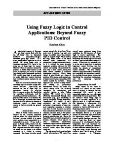
_____________________________________________________________________________________ INTRODUCTION Vehicular traveling is increasing day by day throughout the world, particularly in large urban areas. Current research shows that in many countries, motor vehicle accidents first position among all fatal accidents [1]. By the increasing use of automobiles in cities, accidents are gradually increases now a day. Therefore, it emerging topic of research now a day for optimizing accident controls methods for better accommodating the increasing demand. Therefore, the transportation system will continue to grow, and intelligent accident controls have to employ to face the road congestion’s problems [2]. By application of fuzzy logic it is possible to overcome problems like’s congestion, collision and traffic problems. Driver going behind the other vehicle has to keep such a safety distance that he could avoid the accident in case the other driver in front of him suddenly slowdowns. By realizing of measured distance between the vehicles collision can be minimize by the depending of their speed. Here is the example of the principal of one of the solution to measure distances and speeds for a long time. The measurement can realized by means of retro-reflective sensors. For a retro-reflective application, the transmitter and receiver are placed into the same device. A reflector is placed over opposite to the sensor and transmitted light returns back to the receiver. Retro-reflective sensors are used for medium range (i.e. up to 16m) or average excess gain applications. The effective beam describes the area in order to reliably sense a target and it increases as the distance between the sensor and reflector increases. When the target is in front of the reflector, it must be at least as large as the reflector. Smaller objects can detect if they are close to the sensor and they are large as the optics. So It won´t be collide within them [3]. SOME ACCIDENT CONTROL ALGORITHMS Control Optimization Algorithm Allowing a system to have a better resolution and a faster response, control algorithm is applied to optimized vehicle accident. This upgrade measures the error between the reference point and the current position and converges to zero faster by showing accurate information about the topography of the sample surface. Fig. 1 show the membership functions of both inputs and the output of the fuzzy logic control are tri-angular in the middle. The functions on the sides are linear which saturations after reaching point 1. For better control resolution the area of membership, functions are narrower whose regions are near zero error. On the other hand, for faster control response the area of membership function is made wider, which are far from zero error regions [4]. In order to improve resolution, there are no singletons. All the functions are continuous and there are 3 membership functions for every input and output, which are negative (N), zero (Z) and positive (P) that are shown in table 1[5].
62
Dutta et al Euro. J. Adv. Engg. Tech., 2016, 201 3(1):62-65 ______________________________________________________________________________ Table -1 Rules of Fuzzy Logic
Error
e ∆e
N
Z
P
N Z P
P P P
P Z N
N N N
Error change rate
Output
Fig. 1 Fuzzy logic membership function
The input of the system has been processed by the Fuzzy Logic algorithm and calculates the output, which is called u. In order to reduce e (error), u is the amount of voltage it has to be added to the current voltage (DAQ output). By the addition of these small values to the system which makes it easy to get the desire value or position. For control action, it is necessary to choose the correct values because high values can make the system and process unstable, low values can make it slow. Parameters have to be very accurate values so that we can get controlled task. Changing of large voltage is required to move the system fast but not too large to produce oscillations that will make the system unstable and will take more time to stabilized [6]. [6 Auto-Tune Algorithm Fig. 2 shows the frequency sweep of tuning fork. The main purpose of the Auto-Tune Auto Tune Algorithm is i to increase system efficiency so that time can be saved when it is tuned at its maximum resonance frequency. It is difficult to find and localize the optimal point with the bare eye. For getting more accurate measures, tuning is excited to its maximum sensibility. nsibility. Manual tunes take approximately 1 or 2 minutes based on the experience of the operator. With the proposed algorithm, the tuning operation takes approximately 10 second to enable the system work at its greater sensing potential, which reduces large large amount of time than the manual control as describe earlier. The autoauto tune algorithm has the following steps: • Frequency sweep: Frequencies before maximum (-500Hz) ( 500Hz) and after (+500Hz) is expected which is covered by a sweep, • Recording data: Data is saved corresponding to the amplitude and the frequency of the whole sweep, • Assign the frequency: Take the value of frequency where the amplitude is greater than the others do when the sweep finish. For this procedure, a computer compatible function generator is need so it can program with the aid of Lab VIEW or any other software [6]. An auto-tune tune algorithm for a fuzzy PID controller has been designed and applied to several second order systems. This algorithm is highly effective and can achieve zero overshoot with faster rise time and shorter settling time by producing a faster transient response. The details of the algorithm can summarize as follows. First, a closed-loop closed test is performed by applying the fuzzy PD+I controller on the system. The controller gains gai are set to their default values (one) [7]. ]. The output is enclosed so that the overshoot is not allowed to exceed 100%, where the system becomes unstable. Secondly, if the response exhibits an overshoot with amplitude higher than 1%, the overshoot is measured. sured. The values of the output gain (GU) and gain of the integral of error (GIE) are calculated as follows: GU =Mp (1) GIE = 1 / (2 *Mp) (2) Where Mp is the maximum percentage overshoot. This significantly reduces the overshoot. The gains are kept unchanged when the overshoot is less than 1%. Then, to improve improv the rise-time, time, the value of gain of challenges error (GCE) is decreased and if the system performance is not satisfactory, the value of GIE is increased. The last two steps are performed in an iterative base and the integrated square error (ISE) and the maximum percentage overshoot (Mp) were chosen to measure the performance of the controller [7]. Adaptive Charged System Search (ACSS) Algorithm This algorithm is for optimal tuning of Takagi-Sugeno Takagi Proportional-Integral Integral Fuzzy Controllers (T-S (T PI-FCs) .The five stages of this algorithm are engagement, exploration, explanation, elaboration and evaluation, which involve the adaptation of the acceleration, velocity, separation distance parameters to the iteration index, substitution of the worst charged particles’ les’ fitness function values and positions with the best particles data. The ACSS algorithm
63
Dutta et al Euro. J. Adv. Engg. Tech., 2016, 201 3(1):62-65 ______________________________________________________________________________ solves the optimization problems aiming to minimize the objective functions express as the sum of absolute control error plus squared output sensitivity function, resulting resulting in optimal fuzzy control systems with reduced parametric sensitivity. The search rch ability of this algorithm based on the interactions between charged particles (CPs) that are moving through a predefined domain. CPs is also referred to as agents. Due Due to the good balance between exploration and exploitation offered by the ACSS algorithms, they can conveniently be used to solve discrete and continuous optimization problems with non-convex non objective functions, which eventually have several local minima. The ACSS-based based tuning of T-S T PI-FCs is applied to second-order order servo systems with an integral component. The ACSS algorithm is validated by an experimental case study dealing with the optima tuning of a TT S PI-FC FC for the position control of non-linear non servo system [3].
Fig. 2 Frequency sweep of tuning fork plot
Fig. 3 The flowchart of the auto-tune auto algorithm
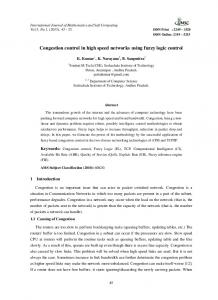
Fig. 4 Schematic block diagram of shear force control system
SHEAR-FORCE LOCATION Controlling the tip-sample sample distance in a scanning near field optical microscope (SNOM) using fuzzy control is needed. The fuzzy controller design assumes only one input signal defined as the difference of the sampled signal (tuning fork-tip) tip) and the reference signal, which are compared through designed software. softwar This signal is used as the rule-base base of the fuzzy logic controller. A basic data acquisition is used as interface to manipulate the fuzzy controller as feedback scheme in the positioning system for shear force control [8]. [ In SNOM, control tip-sample, the manipulation system based on the use of piezoelectric bimorph and due to the nonlinearity characteristics chara of these actuators [9]. The tip to a shear force section is to be conducted by two different approaches have to be done: Large Scale Approximation Micrometrical steps have to be following to get closer to the sample surface. To protect the tip from collisions cause from vibration and external interaction, surface and tip is separated by micrometres. micrometres These steps increase the speed ed and decrease the set up time of the system. Small Scale Approximation The device move the tip until it sensed the shear-force shear force section when the system is close enough to be reachable by the bimorph piezoelectric. The shear-force shear area is small and if the surface is hit, the steps made in this point are capable of breaking the tip of the system. The most sensible approach is the large scale. A distance reference indicator is required to know when the right time to change to the small-scale approximation.
64
Dutta et al Euro. J. Adv. Engg. Tech., 2016, 201 3(1):62-65 ______________________________________________________________________________
Fig. 5(a) The fringes form when the tips are far away
Fig. 5(b) The fringes when the tip is closer to the sample
Fig. 5 Interference fringes created at the sample surface
Some lines do not fit the camera sight and remains wider. For this experiment, the large-scale large approximation is done until only one red line fits the entire screen of the webcam’s view. Once the system approach using largescale procedure is done, the small--scale approximation starts. This approach is made through software softwar with the interface and end when the system decreases the value of its oscillation amplitude. This oscillation is produced by the sinusoidal signal exited with the lock-in lock in amplifier that decrease in amplitude means the shear-force shear area is located [6]. CONCLUSION In this paper, elaborately discuss different way to avoid accident or control accident by using fuzzy logic. Different algorithms are elaborated on, in this paper to minimize averted collision. For better resolution and faster fas response of the system, have done by the control optimization. Auto-Tune Auto Tune algorithm is to increase the efficiency by saving time. The Auto-Tune Tune algorithm presented in this review is a tool to deal with environmental variations and it helps to tune the system in its maximum sensing capacity. ACSS algorithm is applied to the non-linear non control of a class of servo system characterized by second-order second order models with integral component. The capability to vibrate proportionally by shear forces interaction that takes place in a scanning scanning process. Here, Distance can be control by shear force. We looked at how supporting diagrams show in section-III, section III, speed control by maintaining a particular distance and calculating the correct desire value by reducing the error using fuzzy logic control. control REFERENCES [1] Thomas Vimala, Lavanaya and Sridhar, Epidemiologic Profile of Road Traffic Accident (RTA) Cases Admitted in a Tertiary Care Hospital - A Retrospective Study in Hyderabad, Andhra Pradesh, Pradesh International Journal of Medical and Pharmaceutical Sciences iences, 2013, 3 (6), 30-36. [2] Sandeep Mehan, Introduction of Traffic Light Controller with Fuzzy Control System, International Journal of Electronics & Communication Technology, Technology 2011, 2 (3), 1-4. [3] RE Precup, RC David, EM Petriu, Stefan Preitl, MB Rdac, Novel Adaptive Charged System Search Algorithm for Optimal Tuning of Fuzzy Controllers, Journal Expert System with Applications, International Journal Archive, Archive 2014, 41 (4), 1168-1175. [4] Pedro Albertos and Antonio Sala, Fuzzy Logic Controllers, Advantages and Drawbacks, IEEE Transactions on Control System Technology, 1998, 3, 3 833-844. [5] P Srinivas and P Durga Prasada Rao, Comparative Analysis of Conventional PID Controller and Fuzzy Controller er with various Defuzzification Methods in a Three Tank Level Control System, System International Journal of Information Technology, Control and Automation, Automation 2012, 2 (4), 75-86. [6] JA Marquez, R Cortes, HR Siller, V Coello, D Escamilla, Fuzzy Logic Scheme for Tip-Sample Tip Distance Control for a Low Cost Near Field Optical Microscope, Journal of Applied Research and Technology, Technology 2013, 11, 886-894. [7] Bakhtiar I Saeed and B Mehrdadi, Design of an Iterative Auto-Tuning Auto Tuning Algorithm for a Fuzzy PID Controller, Journal of Physics, Conference Service, Service 2014, 364 (1), 1-15. [8] DV Escamilla, HR Siller, F Guedea, R Cortes and V Coello-Cardenas, Cardenas, Feedback Scheme Based on Fuzzy Control for Shear Force Control, IEEE Electronics, Robotics and Automotive Mechanics Conference, Conference 2012, 171175. [9] B Ando, P Giannone, S Graziani and N Pitrone, Measurement System for the Characteristic of Piezoelectric Bimorphs, Proceeding of 19th IMEKO, TC3, TC3 2005.
65