280 Lincoln Street ... 1. Measured constant voltage transmitting response for the transducer used in the ... means of two different acoustic data links, one for.
Acoustic, Communication, Navigation and Sensing Systems for a Biologically-Based Controller for a Shallow Water Walking Machine Donald P. Massa Massa Products Corporation 280 Lincoln Street Hingham, MA 02043
Joseph Ayers Marine Science Center Northeastern University East Point Nahant, MA 01908
Abstract - Underwater robots must be in communication with engineers and scientists who are controlling their activities, and it is also necessary to know the location of the robot. Hard wire communication systems and optical sensors have specific problems when used in the ocean environment. Long cables can become tangled or cut and provide a great deal of drag to the underwater robot, and optical sensing systems become ineffective in murky water, We have been developing several acoustical concepts to solve these problems. Communication is to be performed by an ultrasonic data link, and an ultrasonic transponder system is utilized providing navigation information to the robot. We have performed preliminary experiments with these concepts in a lobster multichannel sonar biotelemetry system which is under development at Northeaster University's Marine Science Center. Muscular activity of lobsters is being monitored and we telemeter information concerning the activity of several muscles to the ocean surface via a unique acoustic data link operating over the frequency range of 30 kHz to 40 kHz. This acoustic system has also been successfully tested in the ocean to provide accurate navigation information when used in conjunction with moored transponders. In addition to communication and navigation, a specialized high-resolution sonar system is under development, which will allow the walking robot to obtain high-resolution acoustic images of all objects on the ocean floor and in the water column around it. I. INTRODUCTION
This paper is being presented in conjunction with a companion paper entitled "A Biologically-Based Controller for A Shallow Water Walking Machine" by
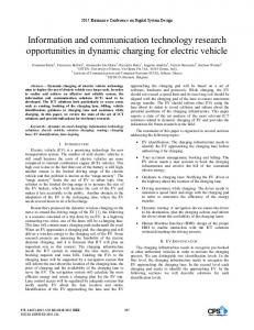
the same authors. This companion paper describes how we are applying neural circuit models of the locomotor control mechanisms of the American lobster to the design of an underwater ambulatory robot [ l , 2, 31. Our robot will walk with eight legs, each of which has the 3 degrees of freedom of the lobster leg. A walking robot is superior to a swimming robot for performing work on the sea floor, particularly in shallow water applications. It is continually in contact with the sea floor, so it is less affected by currents and wave action. In fact, an optimal hydrodynamic shape may hold it more firmly onto the bottom when waves or currents cause water to pass over it. Any remote underwater vehicle should have a means of navigating and communicating with operators on the surface. In addition, the vehicle should be able to obtain high-resolution images of objects around it. This paper will describe acoustical concepts that we plan to use to provide for navigation, communication, and sensing, that allow the robot to operate untethered. 11. NAVIGATION SYSTEM The use of acoustical transponders for navigation is well known in the art [4, 51. We plan to utilize transducers containing electrostrictive ceramic cylinders with a .060" wall 1.00" diameter by 0.375" high that resonate in their circumferential mode at a frequency of 35 kHz. The ceramic is encapsulated in polyurethane that proves waterproofing and also acoustically couples it to the ocean. These transducers are low Q devices that transmit and receive sound in an omnidirectional radiation pattern. Fig. 1 shows a typical constant voltage transmitting response for the transducer, and Fig. 2 shows its receiving response.
590 0-7803-0838-7192 $3.00 0 1992 IEEE
Jill D. Crisman Department of Electrical and Computer Engineering Northeastern University Boston, MA 02115
Frequency kHz
Fig. 1. Measured constant voltage transmitting response for the transducer used in the robot navigation system
We have constructed a navigation system similar to this utilizing the same transducers. Six transponder buoys were anchored in the shallow water off Grape Island in Massachusetts Bay. A command module was then placed in a series of discrete locations in the shallow water area off shore from the island. Fig. 3 shows where the transponders labeled B1 through B6 were anchored,, along with twelve specific places where the command module was located while acoustic measurements were conducted to the six buoys. Six arrows are shown at each command module location. The number at the arrowhead indicates the acoustically measured distance to each of the buoys in meters. The command module was able to successfully communicate with the transponders at ranges of greater than 600 meters, even though the water depth was less than 10 feet.
2or
Frequency kH2
Fig. 2. Measured open circuit receiving response for the transducer used in the robot navigation system
In operation, the navigation system for the robot will consist of a series of anchored transponders that operate in conjunction with a command system on the robot. To determine the location of the robot, its command system will transmit a sonic signal of 35 kHz that radiates through the ocean. When this sound is detected by the buoys, they immediately respond with a reply pulse at a preset frequency different from the command signal. Because the transducers have such a low Q, each transponder can use its own unique reply frequency for identification if desired. The transducer in the command system on the robot detects the reply pulses from the transponders and measures the time from initiation of the command pulse to the reception of the reply signals. Because the position of each of the transponders is known; the identity of each transponder replying is known through its unique frequency, and because the approximate speed of sound is known, the command system can calculate the distance of the robot to each transponder. Then, by triangulation, the position of the robot can be determined.
I
El
I
Lo1
loom
500l - m .
Fig. 3 Schematic representation showing the locations of the six buoys and the twelve positions where acoustic iranges were measured to the buoys. Tests were condlucted in the shallow water off Grape Island in Boston Harbor. (Numbers next to arrows indicate acoustically measured ranges in meters to the buoys towards which the arrows point.)
591
111. COMMUNICATION SYSTEM
It is obviously desirable to have the walking robot untethered, but still under the complete control of an operator located at a remote site. This can easily be accomplished in several ways. For example, a radio link can communicate between the robot and the vessel containing the operator. The radio could be located in the robot with an antenna floated on the surface. Another alternative would be to provide an acoustic data communication link between the robot and a radio transmitter located in a moored buoy or in a floating robot vessel that continually tracks the walking robot and floats over it. The radio link would be used to communicate with an operator on land or on board a ship at sea. The walking robot would then communicate with the transponder buoy or the floating robot by means of two different acoustic data links, one for moderate data rates and the other for high data rates. If a command boat is in the area of the robot's operations, then the acoustic link can be connected directly between the boat and the robot. At the present time, the required data rate of the system is not known. Control commands to the robot will require only a moderate data rate. However, the transmission of data from a High-Resolution Sonar System will require much higher transmission data rates. During the design of the system, data compression techniques will be utilized to the maximum extent possible. For example, the High-Resolution Sonar will contain a classification routine that will identify various objects of interest. Therefore, it will only be necessary to transmit on a continual basis the range and bearing to these targets and detailed highresolution images of specific objects need only be transmitted infrequently. This will make it possible for the robot to perform most of its search activities while operating under moderately low data rate requirements. The reliable rapid transmission of data acoustically underwater is difficult. Transmission is affected by scattering caused by reflections from the surface, the sea floor, and inhomogeneities in the medium, causing a dispersion of the signal in both time and frequency. In addition, in shallow water the pulse length of the signal is stretched due to multiple acoustical paths caused by reflections from the surface and the bottom [6, 7 , 81. Because of these effects, most modulation techniques, such as Amplitude Modulation (AM) and Pulse Position Modulation (PPM) are ineffective. Most state-of-the-art
communication systems utilize Frequency Shift Keying (FSK) for coding [9, 101. In such systems, two frequencies are used. The first is interpreted as a logic "0" and the second is interpreted as a "1". Such a system provides reliable communication even when the signals are distorted by the transmission medium; however, the data rate is required to be slow due to reverberation. Fig. 4 shows an oscillographic recording of the signal received by a hydrophone in the ocean when a short 5 msec pulse was transmitted at 35 kHz. The transmitting transducer and the receiving transducer were separated by approximately 150 feet and the water depth was 35 feet. As can be seen by Fig. 4, a transmit signal 5 msec long produces reverberation for approximately 50 msec. Therefore, if an FSK system were being used for communication, and the 35 kHz signal shown was assigned the value of digital "O",then another "0" could not be transmitted for over 50 msec, which is how long it takes for the reverberation to abate.
Fig. 4. Oscillograph showing 5 msec 35 kHz pulse received at a distance of approximately 150 ft. in 35 feet of water
We plan to use a different approach to increase the rate of communication. Very low Q transducers will he used so that several different frequencies can be transmitted. A communication code will then be devised that will transmit information based on the time interval between the transmission of two different frequencies. For example, suppose the system was designed so that ten different frequencies can be
592
transmitted, and the robot was to transmit its range and bearing to both three different transponder buoys and the targets it is tracking. The communication sequence would start by the transmission of the first frequency f l . The time delay before the transmission of the next frequency f2 would indicate whether the next transmission was the range and bearing to a buoy or to a target. The receiving system would then measure the time between the reception of f l and f2 to decode the information. This time interval is not distorted by the acoustic medium because it only relies on the first arrival of the pulses. Because there is a very large number of discrete time intervals between f l and f2 that can be transmitted, a great amount of information can be sent by this one sequence. Because reverberation will not permit the retransmission of f l or f2 for a relatively long time, the next set of information would be transmitted utilizing the time difference between frequencies f3 and f4. Following this, the next piece of information would be contained in the time difference between fs and fs. In an optimum system design, the Q would be low enough to allow the use of enough frequencies so that by the time the highest frequency has been transmitted, the reverberation from the lowest frequency transmission has died down so that f l can be retransmitted. In the example above, the time interval between f l and f2 could indicate the identity of the object being measured. For example, 1 msec is Buoy I; 2 msec is Buoy 2; 3 msec is Buoy 3; 4 msec is Target I; 5 msec is Target 2, etc. The next interval, between f3 and fd, could then indicate the number of digits in the range. For example, 1 msec is one digit; 2 msec is two digits, etc. If the range is, for example, 153 feet, the interval between f3 and f4 would be 3 msec,, indicating 3 digits. The next three pairs of transmission intervals would then indicate first the digit in the unit’s place, then the digit in the tens place, and finally the digit in the hundredths place. Therefore, the interval between fs and f s would be 3 msec; the interval between fg and f10 would be 1 msec. These series of transmissions has indicated which buoy or target information is being sent, and that its range is 153 feet. The system now is expecting the transmission of the bearing information. The next time interval will therefore indicate the number of digits in the bearing in the same manner as the range information was transmitted. However, because the top frequency of the system has been used, the transmitting frequencies revert back to f l and f2. This poses no
problem because the reverberation has died down from the original transmission on these frequencies. The balance of the bearing data is then transmitted digit by digit in the same manner that the range data was sent. In this manner, basic information can be acoustically transmitted at a moderate data rate without being adversely affected by the ocean’s distortion of the acoustic signals. For these moderate data rates, an omnidirectional transducer system similar to that used in the navigation system can be utilized. Its frequency would obviously have to be slightly different from that used in the nawigation system. It is obvious that any number of communication schemes can be devised using this unique type of Pulse Width Modulation. We have successfully used this method of underwater communication by continually monitoring the electromyographic activities of feeding muscles in the American lobster. The communication channel operates using frequencies of 30 kHz and 40 kHz. Fig. 5 shows a photograph of a lobster carrying the instrumentation package on the top of its carapace. The transmitting transducer is seen on top of the instrumentation package.
Fig. 5 Photograph of lobster carrying the acoustic communication package on its carapace If it is desired to transmit a high-resolution image of an object of interest, much more information would have to be transmitted. This could be accomplished by having the robot remain stationary while a narrow beam, high-frequency transducer is aimed towards a complimentary receiver located either on a buoy or on the hovering robot. This high-frequency array may be a composite design consisting of several arrays resonant at different frequencies to provide a greater bandwidth. It would be acceptable for the walking robot to remain stationary for a short time while the data stream is transmitted.
593
IV. HIGH RESOLUTION SONAR The primary detection system for the walking robot will be a unique High-Resolution Sonar System. Prior art high-resolution sonar systems typically use electronic beam forming or a single narrow beam array is mechanically turned 360" in a similar manner to the way radar antennas are spun [ 111. These systems are both very expensive and mechanically unreliable. Our unique proposed system overcomes these problems. It will consist of approximately sixty separate small highfrequency directional transducer arrays. Each of these arrays will be similar to the deep water side-scan sonar transducers that have been designed and manufactured by Massa Products Corporation. As is well known in the art, a side-scan sonar utilizes a transducer array that produces a narrow acoustic beam in the vertical plane. This transducer array is towed behind a boat, and is repeatedly excited by short electrical signals, each of which produces a fan-shaped acoustic pulse. The transmitted acoustic pulses insonify the entire water column, from the surface to the sea floor, over a narrow horizontal angle of typically 2" to 3". Any objects in the water column, from the surface to the bottom, will reflect the short high-frequency sound wave, and return the resultant reflected echoes to the transducer array. The received echoes are detected by the transducer array, converted to electrical signals, and electronically amplified in a system utilizing time varying gain. The echoes are then displayed on a CRT screen or a recorder. A typical side-scan display showing a sunken boat is shown in Fig. 6, which is a reproduction from page 97 of the book Sonar Images by Dr. Harold E. Edgerton [12]. Dr. Edgerton was a long-recognized pioneer in the field of side-scan sonar technology.
Fig. 6. Typical side-scan sonar image showing highresolution picture of a sunken boat. (From Sonar Images by Dr. Harold E. Edgerton)
As can be seen from Fig. 6, a side-scan sonar display provides a precise detailed picture of the exact structure of what is in the water column or on the sea floor. This picture is more detailed than an image obtained from a scanning sonar system and allows for classification of targets. However, a conventional sidescan sonar must be towed past the target, and therefore cannot produce a complete image from a fixed position in real time. Our proposed High-Resolution Sonar System overcomes this problem by producing the detailed image quality of a side-scan sonar system in real time from a fixed location. We accomplish this by using sixty sidescan type transducer arrays simultaneously. Each array produces a fan-shaped acoustic beam with a 3 " angle in the horizontal plane and a broad beam angle in the vertical plane. Each of the arrays is precisely mechanically indexed in 3 " increments, so that the sixty arrays insonify a total of 180" in the horizontal plane in front of the walking robot. The acoustic arrays will be mounted in a small cylinder on top of the robot. Fig. 7 is a photograph showing in the foreground a single array of twenty 200 kHz transducer elements. This array is 1/4 inch wide by 1/2 inch high by 5 inches long and will produce a fan-shaped beam 3 " wide in the horizontal plane. Above the array is a simulation of one section of the high-resolution sonar containing thirteen arrays incremented in 3" steps. This section of the high-resolution sonar system will insonify a 40 " sector of the ocean.
Fig. 7. Photograph showing a single 3" beam angle array of twenty 200 kHz transducer elements, and a simulation of 13 of these arrays mechanically incrernented 3" each to produce a portion of the high-resolution sonar system that will insonify a 40" sector
594
The received echoes from all arrays will be amplified by the time varying gain electronics, and images similar to that shown in Fig. 6 can be displayed. The entire image will be completely updated each time the system transmits, which can be as fast as once per second. To minimize the required data transmission rate, the sonar system will contain a classification routine that will determine objects of interest and only transmit their range and bearings until commanded by the operator to transmit the complete sonar image to the operator's CRT for final classification.
V. CONCLUSIONS We have presented several concepts for providing unique acoustic systems to operate with our ambulatory robot. We have shown how an acoustic navigation system, a communication system, and a high-resolution sonar can be designed and fabricated. In addition, we have provided laboratory and "in situ" data collected on several components of these systems.
REFERENCES [I] Ayers, J. and W. J. Davis, "Neuronal Control of Locomotion in the Lobster. I Motor Programs for Forward and Backward Walking", J . Comp. Physiol.. 115:l-24, 1977
[2] Ayers, J. and W. J . Davis, "Neuronal Control of Locomotion in the Lobster. I1 Types of Walking Leg Reflexes", J. Comp. Physiol., 115:25-46,1977 [3] Ayers, J. and J. Crisman, "The Lobster as a Model for an Omnidirectional Robotic Ambulation Control Architecture", In Biologics/ Neural Networks in Invertebrate Neuroethology and Robots, (R. Beer, R. Ritzman and T. McKenna, ed.) in press, 1992. [4] Woodward, B. and H. Sharp, "Portable Real Time Diver Navigation System", Ultrasonics, Vol. 29, September, 1991 [SI Berntsen, Morton, "Principles and Practice of Acoustic Navigation Systems", Underwater Systems Design, January/Febiruary 1992 [6] Urick, Robert J., Sound Propagation in the Sea, Peninsula Publishuig, Los Altos, CA, 1982, Chapter 14 [q Chan, Y.T., "Time Delay Estimation in the Presence of Multipath Propagation" Proceedings of the NATO Advanced Study Institute on Adoptive Methods in Underwater Acoustics, (H.G. Urban, ed.) Reidel Publishing Co., Dordrecht, Holland 1985, pp. 197-206 [8] Bobber, Robert J., Underwater Electroacoustic Measurements, Peninsula Riblishing, Los Altos, CA, 1988, pp. 143-155 [9] Riter, Stephen "Acoustic Telemetry and Signal Processing", Lectures on Marine Acoustics Volume 11- Part 1 Selected Advanced Tquics, Texas A&M Universiy Sea Grant Publication No. TAMU-SG-73-403 (J.W. Caruthers, ed.) 1971, pp. 4-10 [lo] Brock, D.C., S.C. Bateman and B. Woodward, "Underwater Acoustic Transmission of Low-Rate Digital Data" Ultrasonics Vol. 24, Jul:y 1986 Ill] Imageiiex Tech. Corp., "Principles of Sonar Imaging" Underwater Systems Dmign, November/December 1991 [I21 Edgerton, Harold E. Scnar Images, Preiitice-Hall, Englewood Cliffs, NJ, 1986, p. 97
595