Hindawi Publishing Corporation Mathematical Problems in Engineering Volume 2015, Article ID 374838, 14 pages http://dx.doi.org/10.1155/2015/374838
Research Article Adaptive Neural Back-Stepping Control with Constrains for a Flexible Air-Breathing Hypersonic Vehicle Pengfei Wang, Jie Wang, Jianming Shi, Chang Luo, Shili Tan, and Qiyun Xu Air and Missile Defense College, Air Force Engineering University, Xi’an 710051, China Correspondence should be addressed to Pengfei Wang;
[email protected] Received 17 May 2015; Revised 25 October 2015; Accepted 8 November 2015 Academic Editor: Xinggang Yan Copyright © 2015 Pengfei Wang et al. This is an open access article distributed under the Creative Commons Attribution License, which permits unrestricted use, distribution, and reproduction in any medium, provided the original work is properly cited. The design of an adaptive neural back-stepping control for a flexible air-breathing hypersonic vehicle (AHV) in the presence of input constraint and aerodynamic uncertainty is discussed. Based on functional decomposition, the dynamics can be decomposed into the velocity subsystem and the altitude subsystem. To guarantee the exploited controller’s robustness with respect to parametric uncertainties, neural network (NN) is applied to approximate the lumped uncertainty of each subsystem of AHV model. The exceptional contribution is that novel auxiliary systems are introduced to compensate both the tracking errors and desired control laws, based on which the explored controller can still provide effective tracking of velocity and altitude commands when the actuators are saturated. Finally, simulation studies are made to illustrate the effectiveness of the proposed control approach in spite of the flexible effects, system uncertainties, and varying disturbances.
1. Introduction Air-breathing hypersonic vehicles (AHV) are crucial because they may represent a more efficient way to make access to space routine or even make the space travel routine and intercontinental travel as easy as intercity travel. A key issue in making AHV feasible and efficient is the flight control design [1]. However, the flight control of AHV is still an open challenge due to its peculiarity of flight dynamics. It is worth noting that there exists strong coupling between the propulsive and the aerodynamic forces, which makes the aerodynamic characteristics of AHV very difficult to be estimated and measured [2, 3]. Recently, lots of efforts have been put into flight control for AHV. Linear control theory was widely employed for flight control design based on linearized model. As shown in [4], the robust control of AHV is studied by introducing a linear quadratic regulator (LQR) with stochastic robustness analysis. In [5], LQR controller is proposed for the linearization model based on any equilibrium points of flight envelope. Nonlinear control scheme is also employed for AHV. Back-stepping has been proved to be a powerful tool for the tracking control of a large class of strict-feedback systems or pure-feedback ones [6–12]. Back-stepping design
for nonlinear systems consists of a recursive design procedure, which breaks down the full system control problem into a sequence of designs for lower-order subsystems. A back-stepping controller is designed with multilayer online adaptive neural networks, which can provide good tracking performance [13]. In [14], a combination of novelty command filtered back-stepping technology and dynamic inversion methodology is adopted for designing a dynamic state-feedback controller that provides stable tracking of the altitude and velocity reference commands. However, it is well known that there exists a problem of “explosion of terms” in the traditional back-stepping design, which is caused by the repeated differentiations of virtual control laws. To solve this problem, dynamic surface control [15] and tracking differentiators [16] should be applied. Since the aerodynamic characteristics of AHV are sensitive to the flight condition changes, they are difficult to be measured. Thus, the aerodynamic uncertainty needs to be dealt with at the control design as the main issues. Conventionally, the flight control is accomplished by feedback linearization with neural networks to deal with the uncertainties. Efforts in [17] approximate the unknown nonlinear functions by radial basis function networks and incorporating the dynamic surface technique into a neural network
2
Mathematical Problems in Engineering
based adaptive control design framework. Reference [18] investigates the discrete time controller for the longitudinal dynamics of the hypersonic flight vehicle with throttle setting constraint. The controller is proposed by estimating the system uncertainty and unknown control gain separately with neural networks. The auxiliary error signal is designed to compensate the effect of throttle setting constraint. Moreover, input constraint also cannot be ignored in practice since the outputs of actuators are constrained for physical limitations. If the input constraint is ignored, control systems may suffer from performance limitations or even lose stability [19–21]. Much literature theoretically focuses on the control problem with input constraint [22– 26]. In practice, when input constraint occurs, aircraft body may change seriously even disintegrating. So it is necessary to research the control design problem with input constraint. Motivated by the results of the previous studies, an adaptive neural back-stepping control approach is addressed for the longitudinal dynamical model of AHV. By viewing the flexible effects as system uncertainties, the longitudinal dynamics of AHV are decomposed into two functional subsystems, namely, the respective velocity subsystem and altitude subsystem. To ensure the controller’s robustness, NNs are applied to estimate the lumped uncertainty of each subsystem. Particularly, novel auxiliary systems are exploited to deal with the problem of control input constraint. Finally, simulation results are presented to demonstrate the efficacy of the proposed control methodology. The special advantages of the approach proposed herein include the following: (1) The novel auxiliary systems are employed to eliminate the error between the desired control laws and actual control laws, which makes sure that the semiglobally uniformly bounded stability of closed-loop system can be still achieved even when the physical limitations are in effect. (2) The second-order reference model is designed for the precise estimation of the derivatives of virtual control laws, which predigests the design of controller. The organization of paper is outlined as follows. Firstly, the longitudinal motion model and control-oriented model of an AHV are described in Section 2. Section 3 presents the design procedures of adaptive neural backstepping controller. Then, simulation results are given in Section 4. Finally, brief concluding remarks end the paper in Section 5.
2. Problem Formulation 2.1. Longitudinal Dynamic Model of AHV. The model taken into consideration in this paper is developed by Bolender and Doman [27] for the longitudinal dynamics of an AHV. The flexible effects are included in these equations by modeling the vehicle as a single flexible structure with mass-normalized mode shapes.
Assuming a flat Earth and normalizing the span of an AHV to unit depth, the nonlinear motion equations are written as [27] 𝜇 sin 𝛾 𝑇 cos 𝛼 − 𝐷 , − 𝑉̇ = 2 𝑚 (𝑅𝐸 + ℎ) ℎ̇ = 𝑉 sin 𝛾, 𝛾̇ =
2 𝐿 + 𝑇 sin 𝛼 [𝜇 − 𝑉 (𝑅𝐸 + ℎ)] cos 𝛾 , − 2 𝑚𝑉 𝑉 (𝑅𝐸 + ℎ)
(1)
𝛼̇ = −𝛾̇ + 𝑄, 𝑧 𝑇+𝑀 𝑄̇ = 𝑇 , 𝐼𝑦𝑦 𝜂𝑖̈ = −2𝜁𝑖 𝜔𝑖 𝜂𝑖̇ − 𝜔𝑖2 𝜂𝑖 + 𝑁𝑖 , 𝑖 = 1, 2, 3, where the rigid body states 𝑉, ℎ, 𝛾, 𝜃, and 𝑄 represent velocity, altitude, flight path angle, pitch angle, and pitch rate, respectively; 𝜇 and 𝑅𝐸 are gravity constant and the radial distance from center of the earth; 𝑚 and 𝐼𝑦𝑦 are mass of vehicle and moment of inertia about pitch axis; 𝑇, 𝐷, 𝐿, and 𝑀 represent thrust, drag, lift, and pitch moment, respectively; 𝑧𝑇 denotes the thrust moment arm; the flexible states 𝜂 = 𝑇 [𝜂1 𝜂1̇ 𝜂2 𝜂2̇ 𝜂3 𝜂3̇ ] denote the first three bending modes of the fuselage; 0 < 𝜁𝑖 < 1 and 𝜔𝑖 > 0 (𝑖 = 1, 2, 3) mean the damping ratio and natural frequency of the mass-normalized generalized coordinates of the flexible structure. The dynamic system of an AHV can be decomposed as velocity subsystem and altitude-related subsystem. Define the control inputs 𝑢 = [Φ, 𝛿𝑒 ], which are fuel equivalence ratio and elevator angular deflection, respectively. Remark 1. In [28], the controller design requires an auxiliary actuator as the canard. However, the presence of a canard is quite problematic for the vehicle configuration, as this control surface must withstand the expected high temperatures at hypersonic speed. Therefore, it is assumed that only the fuel-to-air ratio and elevator are the actuators available for controlling the vehicle. Let 𝐿 = 𝐿 + 𝑇 sin 𝛼.
(2)
The thrust 𝑇, drag 𝐷, lift 𝐿, pitch moment 𝑀, and generalized forces 𝑁𝑖 (𝑖 = 1, 2, 3) are defined as 𝑇 = 𝑞𝑆𝐶𝑇 (𝛼, 𝑀𝑎, Φ) + 𝜀𝑇 (x, 𝜂, u) , 𝐷 = 𝑞𝑆𝐶𝐷 (𝛼, 𝑀𝑎, 𝛿𝑒 ) + 𝜀𝐷 (x, 𝜂, u) , 𝐿 = 𝑞𝑆𝐶𝐿 (𝛼, 𝑀𝑎, Φ) + 𝜀𝐿 (x, 𝜂, u) , 𝑀 = 𝑞𝑆𝑐𝐶𝑀 (𝛼, 𝑀𝑎, 𝛿𝑒 ) + 𝜀𝑀 (x, 𝜂, u) , 𝐶𝑇 (𝛼, 𝑀𝑎, Φ) = 𝐶𝑇0 (𝛼, 𝑀𝑎) + 𝐶𝑇Φ (𝛼, 𝑀𝑎, Φ) Φ, 𝛿
0 𝐶𝑀 (𝛼, 𝑀𝑎, 𝛿𝑒 ) = 𝐶𝑀 (𝛼, 𝑀𝑎) + 𝐶𝑀𝑒 (𝛼, 𝑀𝑎, 𝛿𝑒 ) 𝛿𝑒 ,
Mathematical Problems in Engineering
3
𝐶𝐿 (𝛼, 𝑀𝑎, Φ) = 𝐶𝐿0 (𝑀𝑎, Φ) + 𝐶𝐿𝛼 (𝛼, 𝑀𝑎, Φ) 𝛼, 2
𝜂
𝛿
𝑁𝑖 ≈ 𝑞𝑆 [𝑁𝑖𝛼 𝛼2 + 𝑁𝑖𝛼 𝛼 + 𝑁𝑖 𝑒 𝛿𝑒 + 𝑁𝑖0 + 𝑁𝑖 𝜂] , (3) where 𝑞, 𝑆, and 𝑐 stand for the respective dynamic pressure, reference area, and aerodynamic chord. 𝜀𝑇 , 𝜀𝐿 , 𝜀𝐷, and 𝜀𝑀 are denoted as the fitting error of 𝑇, 𝐿, 𝐷, and 𝑀, respectively. To be convenient for design of back-stepping, (1) can be rewritten as 𝑉̇ = 𝑓𝑉 (𝑞, 𝑀𝑎, 𝛼, 𝛿𝑒 ) + 𝑔𝑉 (𝑞, 𝛼, 𝑀𝑎, Φ) Φ + 𝐹𝑉 (4) + Δ 𝑉 (x, 𝜂, u) , ℎ̇ = 𝑉𝛾 + Δ ℎ (𝑉, 𝛾) ,
(5)
𝛾̇ = 𝑓𝛾 (𝑞, 𝑀𝑎, Φ) + 𝑔𝛾 (𝑞, 𝛼, 𝑀𝑎, Φ) 𝛼 + 𝐹𝛾 + Δ 𝛾 (x, 𝜂, u) , 𝛼̇ = 𝑓𝛼 (𝑞, 𝛼, 𝑀𝑎, Φ) + 𝑄 + 𝐹𝛼 + Δ 𝛼 (x, 𝜂, u) , 𝑄̇ = 𝑓𝑄 (𝑞, 𝛼, 𝑀𝑎, Φ) + 𝑔𝑄 (𝑞, 𝛼, 𝑀𝑎, Φ, 𝛿𝑒 ) 𝛿𝑒 + Δ 𝑄 (x, 𝜂, u)
(6) (7) (8)
with 𝑓𝑉 =
𝑞𝑆 (𝐶𝑇0 cos 𝛼 − 𝐶𝐷)
𝑚 Φ cos 𝛼 , 𝑔𝑉 = 𝑞𝑆𝐶𝑇 𝑚 𝑓𝛾 =
𝑞𝑆𝐶𝐿0 , (𝑚𝑉)
𝑔𝛾 =
𝑞𝑆𝐶𝐿𝛼 , (𝑚𝑉)
,
Remark 2. The flexible dynamics are taken as perturbations on the rigid body system, and their effects are evaluated in simulation. According to (1) and (4), 𝜂𝑖 would be asymptotic stability if Φ, 𝛿𝑒 , and 𝛼 are bounded. 2.2. Control Objective. In practice, due to physical limitations, the outputs of the actuator are constrained. Input constraints studied in the paper include the constraint on fuel equivalence ratio, elevator deflection. The constraint on fuel equivalence ratio is imposed by the very nature of the propulsion system, which is required to maintain the conditions that sustain scramjet operation [29]. If the limit is violated, the thermal choking will occur. It could induce that engine unstarts which could jeopardize mission, vehicle, and its contents [30]. The constraints on elevator deflection and canard deflection are mainly imposed by the limits on control surface displacement. The above input constraint can be expressed as
𝛿𝑒 = 𝛿𝑒max , 𝛿𝑒𝑐 ≥ 𝛿𝑒max ,
(11)
𝛿𝑒 = 𝛿𝑒𝑐 , 𝛿𝑒min ≤ 𝛿𝑒𝑐 ≤ 𝛿𝑒max , 𝛿𝑒 = 𝛿𝑒min , 𝛿𝑒𝑐 ≤ 𝛿𝑒min ,
𝐼𝑦𝑦
(9) ,
𝑞𝑆𝑐𝐶𝑀𝑒 , 𝐼𝑦𝑦 𝜇 sin 𝛾 (𝑅𝐸 + ℎ)
𝐹𝛾 = −𝐹𝛼 = −
(10)
Φ = Φmin , Φ𝑐 ≤ Φmin ,
0 𝑞𝑆 [𝑧𝑇 (𝐶𝑇0 + 𝐶𝑇Φ Φ) + 𝑐𝐶𝑀 ]
𝐹𝑉 = −
(𝑧𝑇 𝜀𝑇 + 𝜀𝑀) . 𝐼𝑦𝑦
Φ = Φ𝑐 , Φmin ≤ Φ𝑐 ≤ Φmax ,
𝛿
𝑔𝑄 =
Δ 𝑄 (x, 𝜂, u) =
Φ = Φmax , Φ𝑐 ≥ Φmax ,
𝑓𝛼 = − (𝑓𝛾 + 𝑔𝛾 𝛼) , 𝑓𝑄 =
𝜀𝐿 , 𝑚𝑉 𝜀 Δ 𝛼 (x, 𝜂, u) = − 𝐿 , 𝑚𝑉 Δ 𝛾 (x, 𝜂, u) =
2
,
[𝜇 − 𝑉2 (𝑅𝐸 + ℎ)] cos 𝛾 2
[𝑉 (𝑅𝐸 + ℎ) ]
The model errors are considered as Δ 𝑉 (x, 𝜂, u) = Δ ℎ (𝑉, 𝛾) =
(𝜀𝑇 cos 𝛼 − 𝜀𝐷) , 𝑚 𝑉𝛾2 sin 𝛾 , 2
.
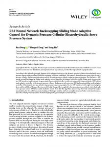
where Φmax and Φmin denote the upper and lower bound of Φ, respectively; 𝛿𝑒max and 𝛿𝑒min stand for the upper and lower bound of 𝛿𝑒 , respectively; Φ𝑐 and 𝛿𝑒𝑐 are the desired control inputs to be designed in the subsequent section. A second-order reference model with amplitude, rate, and bandwidth limitation is introduced to deal with the input constraint. The structure of second-order reference model is given in Figure 1. Φ0 , 𝛿𝑒0 , and 𝛾𝑐0 , 𝛼𝑐0 , and 𝑄𝑐0 are the designed actual control variables and virtual control variables. Define Φ, 𝛿𝑒 , and 𝛾𝑐 , 𝛼𝑐 , and 𝑄𝑐 as the executable control laws and virtual control laws with the second-order reference model. 2.3. Radial Basis Function NN Approximation. The radial basis function NN (RBFNN) will be introduced to approach the unknown functions 𝑓𝑥 (z) and 𝑔𝑥 (z) (𝑥 = 𝑉, 𝛾, 𝑄) owing to its excellent performance and global approximation. It has been proved that RBFNN can approximate an arbitrary continuous function over a compact set Ωz ⊆ R𝑛 to an arbitrary accuracy. RBFNN is formulated as 𝜃𝑇 𝜉(z) with the input vector z ⊆ R𝑛 , the weight vector 𝜃 ⊆ R𝑚 , the basis
4
Mathematical Problems in Engineering {Φ,̇ 𝛿̇ e } {𝛾̇ c , 𝛼̇ c , Q̇ c }
ẋ c xcU
xc0 {Φ0 , 𝛿0e }
+ xcL
{𝛾0c , 𝛼0c , Qc0 } Magnitude limiter
−
𝜔2n 2𝜁n 𝜔n
{Φ, 𝛿e }
Rx
+ −Rx
1 s
2𝜁n 𝜔n −
1 s
xc {𝛾c , 𝛼c , Qc }
Rate limiter
Figure 1: Second-order reference model.
function vector 𝜉(z) ⊆ R𝑚 , the node number 𝑚, and the input number 𝑛. The basis function is selected as the following Gaussian function: 2 z − c𝑖 ) , 𝑖 = 1, 2, . . . , 𝑚, 𝜉𝑗 (z) = exp (− 2𝑏𝑖2
(12)
where c𝑖 = [𝑐𝑖1 , 𝑐𝑖2 , . . . , 𝑐𝑖𝑚 ]𝑇 and 𝑏𝑖 stand for the center and width of Gaussian function, respectively. Assumption 3. 𝑓𝑥 (𝑧) and 𝑔𝑥 (𝑧) (𝑥 = 𝑉, 𝛾, 𝑄) are continuous real function. The unknown functions 𝑓𝑥 (z) and 𝑔𝑥 (z) can be designed as ∗ 𝑓𝑥 (z) = 𝜃∗𝑇 𝑓𝑥 𝜉𝑓𝑥 (z) + 𝜀𝑓𝑥 ,
where ̂ ^, 𝛽) Proj (𝜃, ̂ ^ − 𝛽𝜃, { { { { ={ { ̂ { {^ − 𝛽𝜃 − {
𝑇 𝜃̂𝜃̂ ^ ̂2 , 𝜃
𝑇 𝑖𝑓 𝜃̂ < 𝜃𝑀 𝑜𝑟 𝜃̂ = 𝜃𝑀, 𝜃̂ ^ ≤ 0 (17) 𝑇 𝑖𝑓 𝜃̂ = 𝜃𝑀, 𝜃̂ ^ > 0;
̂ then ‖𝜃(𝑡)‖ ≤ 𝜃𝑀; 𝜃𝑀 is positive constant.
3. Controller Design
where 𝜉𝑓𝑥 (z) and 𝜉𝑔𝑥 (z) are radial basis function vector; 𝜀𝑓∗𝑥 and 𝜀𝑔∗𝑥 denote the approximation error, and |𝜀𝑓∗𝑥 | ≤ 𝜀𝑓𝑀𝑥 and |𝜀∗ | ≤ 𝜀𝑀; 𝜃∗ and 𝜃∗ represent optimal weight vector, 𝜃̂
The control objective pursued in this section is to develop an adaptive neural back-stepping controller for an AHV to provide robust tracking of velocity and altitude commands 𝑉ref and ℎref . It is assumed that the rigid body states 𝑉, ℎ, 𝛾, 𝛼, and 𝑄 are available for measurement. It is easy to note that the velocity 𝑉 is mainly related to Φ and the altitude ℎ is mainly affected by 𝛿𝑒 since the thrust 𝑇 affects 𝑉 and 𝛿𝑒 has a dominant contribution to ℎ change in (1). In what follows, the respective control laws Φ and 𝛿𝑒 will be designed to make 𝑉 → 𝑉ref and ℎ → ℎref .
Lemma 4. According to
𝑀 Assumption 6. Consider sup |Δ 𝑥 | ≤ Δ𝑀 𝑥 ; Δ 𝑥 is positive 𝑀 𝑀 𝑀 ̂ ̃ constant. Define Δ 𝑥 = Δ 𝑥 − Δ 𝑥 which stand for the estimation error of Δ𝑀 𝑥.
∗ 𝑔𝑥 (z) = 𝜃∗𝑇 𝑔𝑥 𝜉𝑔𝑥 (z) + 𝜀𝑔𝑥 ,
𝑔𝑥
𝑔𝑥
𝑓𝑥
(13)
𝑓𝑥
𝑔𝑥
and 𝜃̂𝑔𝑥 are the estimation of 𝜃∗𝑓𝑥 and 𝜃∗𝑔𝑥 , respectively, and 𝜃̃𝑓𝑥 = 𝜃∗𝑓𝑥 − 𝜃̂𝑓𝑥 and 𝜃̃𝑔𝑥 = 𝜃∗𝑔𝑥 − 𝜃̂𝑔𝑥 are estimation error of 𝜃∗𝑓𝑥 and 𝜃∗𝑔𝑥 , respectively.
𝑇 1 𝑇 ̂ ̃ + (𝜃∗ − 𝜃) ̂ 𝑇 𝜃] 𝜃̃ 𝜃̂ = [𝜃̃ (𝜃∗ − 𝜃) 2
1 2 2 2 = [− 𝜃̃ − 𝜃̂ + 𝜃∗ ] 2
(14)
3.1. Controller Design for Velocity Subsystem. Differentiating ̃ = 𝑉 − 𝑉ref with respect to time the velocity track error 𝑉 results in
there exist 𝑇 1 2 2 𝜃̃ 𝜃̂ ≤ [− 𝜃̂ + 𝜃∗ ] , 2 𝑇 1 2 2 𝜃̃ 𝜃̂ ≤ [− 𝜃̃ + 𝜃∗ ] . 2
(15) ̃̇ = 𝑓𝑉 + 𝑔𝑉Φ + 𝐹𝑉 + Δ 𝑉 − 𝑉ref ̇ 𝑉
Lemma 5 (see [31]). The adaptive law of 𝜃̂ is designed as ̇ ̂ ^, 𝛽) , 𝜃̂ = ΓProj (𝜃,
Γ > 0, 𝛽 > 0,
Lemma 7 (see [32]). If 𝑥 ∈ R and 𝜀 > 0, then 0 ≤ |𝑥| − 𝑥 tanh(𝑥/𝜀) ≤ 𝑘𝜀, 𝑘 = 0.2785.
= 𝑓̂𝑉 + 𝑔̂𝑉Φ0 + [(𝑓𝑉 − 𝑓̂𝑉) + (𝑔𝑉 − 𝑔̂𝑉) Φ] (16)
̇ + 𝑔̂𝑉 (Φ − Φ0 ) + 𝐹𝑉 + Δ 𝑉 − 𝑉ref
(18)
Mathematical Problems in Engineering
5 Differentiating 𝑊𝑉 with respect to time results in
with
̃2 + 𝑘𝑉,3 𝑉𝜆 ̃ 𝑉 − 𝜅𝑉𝜆2 + 𝑉 ̃ (𝜀∗ + 𝜀∗ Φ) 𝑊̇ 𝑉 = −𝑘𝑉,1 𝑉 𝑉 𝑓𝑉 𝑔𝑉
(𝑓𝑉 − 𝑓̂𝑉) + (𝑔𝑉 − 𝑔̂𝑉) Φ 𝑇
𝑇
= (𝜃∗𝑓𝑉 − 𝜃̂𝑓𝑉 ) 𝜉𝑓𝑉 + (𝜃∗𝑔𝑉 − 𝜃̂𝑔𝑉 ) 𝜉𝑔𝑉 Φ + 𝜀𝑓∗𝑉
̂ 𝑀 tanh ( ̃ [Δ 𝑉 − Δ +𝑉 𝑉
(19)
+ 𝜀𝑔∗𝑉 Φ.
̃ 𝑉 ̃ ̃ 𝑀 Δ 𝑉 )] + 𝑉 𝜀𝑉
𝑇
𝑇
̃ ̂ ̃ ̂ ̃ 𝑀Δ ̂𝑀 − 𝛽𝑉 Δ 𝑉 𝑉 − 𝛽𝑓𝑉 𝜃𝑓𝑉 𝜃𝑓𝑉 − 𝛽𝑔𝑉 𝜃𝑔𝑉 𝜃𝑔𝑉
To eliminate the error between Φ and Φ0 , a novel auxiliary system is introduced as 𝜆̇ 𝑉 = −𝜅𝑉𝜆 𝑉 −
̃𝑔̂𝑉 (Φ − Φ0 ) 𝑉 𝜆𝑉
,
(20)
where 𝜅𝑉 > 0 is a design parameter. The adaptive law of weight vector can be designed as
𝑇 When ‖𝜃̂𝑔𝑉 ‖ ≤ 𝜃𝑔𝑀𝑉 and 𝜃̂𝑔𝑉 ≤ 0, 𝜐𝑓𝑉 = 𝜐𝑔𝑉 = 0; when ‖𝜃̂𝑔𝑉 ‖ = 𝜃𝑔𝑀𝑉 and 𝜃̂𝑔𝑇𝑉 > 0, 𝜐𝑓𝑉 = 𝜐𝑔𝑉 = 1. Invoking Lemma 7, we have
(21)
̇ ̃ 𝛽𝑔 ) , 𝜃̂𝑔𝑉 = Γ𝑔𝑉 Proj (𝜃̂𝑔𝑉 , 𝜉𝑔𝑉 Φ𝑉, 𝑉
where Γ𝑓𝑉 = Γ𝑇𝑓𝑉 , Γ𝑔𝑉 = Γ𝑇𝑔𝑉 , and 𝛽𝑓𝑉 and 𝛽𝑔𝑉 are design parameters. The adaptive law of Δ𝑀 𝑉 is given as follows: (22)
̃ 𝑉 ̃ ̃ 𝑀 ̂ 𝑀 ̃ ̃ Δ 𝑉 + Δ 𝑉 [𝑉 − 𝑉 tanh ( )] ≤ 𝑉 𝜀𝑉
Substituting (27) into (26) results in ̃ − 𝜇𝑉,2 𝜆 𝑉)2 𝑊̇ 𝑉 ≤ −𝜇𝑉,1 (𝑉 ̃ − 𝜇𝑉,4 (𝜀∗ + 𝜀∗ Φ)] − 𝜇𝑉,3 [𝑉 𝑓𝑉 𝑔𝑉
𝑡
𝑇
𝑇
where 𝜇𝑉,1 =
where 𝑘𝑉,1 and 𝑘𝑉,2 are positive constants to be designed. Plugging (23) into (18) results in 𝑡
̃̇ = −𝑘𝑉,1 𝑉 ̃ − 𝑘𝑉,2 ∫ 𝑉𝑑𝜏 ̃ + 𝑘𝑉,3 𝜆 𝑉 + 𝜃̃𝑇 𝜉𝑓 𝑉 𝑓𝑉 𝑉
𝜇𝑉,2 =
(24)
,
2𝜅𝑉 , 𝑘𝑉,3
𝜇𝑉,4 =
(29)
1 , (2𝜇𝑉,3 )
According to 2𝑥𝑦 ≤ 𝑐𝑥2 + (1/𝑐)𝑦2 , we obtain ̂ 𝑀)2 (𝑘 𝜀 )2 𝛽𝑉 (Δ ̂ 𝑀 𝑉 𝑘𝑉 Δ 𝑉 𝜀𝑉 ≤ + 𝑉 𝑉 . 2 2𝛽𝑉
The Lyapunov function can be designed as 2
1 𝑇 1 ̃𝑇 −1 ̃ ̃ + 𝜃̃𝑓𝑉 Γ−1 𝑓𝑉 𝜃𝑓𝑉 + 𝜃𝑔𝑉 Γ𝑔𝑉 𝜃𝑔𝑉 . 2 2
(4𝜅𝑉)
2 . 𝜇𝑉,5 = 𝜇𝑉,3 𝜇𝑉,4
̃ ̂ 𝑀 tanh ( 𝑉 )] . + [Δ 𝑉 − Δ 𝑉 𝜀𝑉
1 ̃2 𝑘𝑉,2 1 1 ̃𝑀 2 ̃ + + 𝜆2𝑉 + (Δ 𝑉 ) 𝑊𝑉 = 𝑉 (∫ 𝑉𝑑𝜏) 2 2 2 2𝜎𝑉 0
2 𝑘𝑉,3
𝜇𝑉,3 = 𝑘𝑉,1 − 𝜇𝑉,1 ,
0
𝑡
(28)
− 𝛽𝑓𝑉 𝜃̃𝑓𝑉 𝜃̂𝑓𝑉 − 𝛽𝑔𝑉 𝜃̃𝑔𝑉 𝜃̂𝑔𝑉 , (23)
𝑇 + 𝜃̃𝑔𝑉 𝜉𝑔𝑉 Φ + 𝜀𝑓∗𝑉 + 𝜀𝑔∗𝑉 Φ + 𝑔̂𝑉 (Φ − Φ0 )
2
2 ̂ 𝑀 ̃𝑀 ̂𝑀 + 𝜇𝑉,5 (𝜀𝑓∗𝑉 + 𝜀𝑔∗𝑉 Φ) + 𝑘𝑉 Δ 𝑉 𝜀𝑉 − 𝛽𝑉 Δ 𝑉 Δ 𝑉
̃ − 𝑘𝑉,2 ∫ 𝑉𝑑𝜏 ̃ + 𝑘𝑉,3 𝜆 𝑉 − 𝐹𝑉 + 𝑉ref ̇ Φ0 = 𝑔̂𝑉−1 [−𝑘𝑉,1 𝑉 ̃ ̂ 𝑀 tanh ( 𝑉 )] , − 𝑓̂𝑉 − Δ 𝑉 𝜀𝑉
(27)
̃ ̃ 𝑀 ̂ 𝑀 Δ 𝑉 + 𝑘𝑉 Δ ≤ − 𝑉 𝑉 𝜀𝑉.
where 𝜎𝑉 and 𝛽𝑉 are design parameters. The desired controller Φ0 is introduced as
0
𝑇
̃ ̃ 𝜃̂𝑓 𝜉𝑓 𝑉 𝜃̂𝑔 𝜉𝑔 Φ𝑉 𝑇 𝑇 − 𝜐𝑓𝑉 𝜃̃𝑓𝑉 𝜃̂𝑓𝑉 𝑉 𝑉2 − 𝜐𝑔𝑉 𝜃̃𝑔𝑉 𝜃̂𝑔𝑉 𝑉 𝑉2 . 𝜃̂ 𝜃̂ 𝑓𝑉 𝑔𝑉
̃ ̃ [Δ 𝑉 − Δ ̂ 𝑀 tanh ( 𝑉 )] 𝑉 𝑉 𝜀𝑉
̇ ̃ − 𝛽𝑓 𝜃̂𝑓 ) , 𝜃̂𝑓𝑉 = Γ𝑓𝑉 (𝜉𝑓𝑉 𝑉 𝑉 𝑉
𝑀 ̃ ̂̇ = 𝜎𝑉 (𝑉 ̂𝑀 Δ 𝑉 − 𝛽𝑉 Δ 𝑉 ) ,
𝑇
(26)
(25)
(30)
Invoking Lemma 4, it is deduced as ̃ 𝑀Δ ̂ 𝑀 𝛽𝑉 [− (Δ ̂ 𝑀)2 + (Δ𝑀)2 ] , ̃ 𝑀)2 − (Δ 𝛽𝑉 Δ 𝑉 𝑉 = 𝑉 𝑉 𝑉 2
(31)
6
Mathematical Problems in Engineering 𝑇
𝛽𝑓𝑉 𝜃̃𝑓𝑉 𝜃̂𝑓𝑉 ≤ 𝑇 𝛽𝑔𝑉 𝜃̃𝑔𝑉 𝜃̂𝑔𝑉 ≤
𝛽𝑓𝑉
2 2 [− 𝜃̃𝑓𝑉 + 𝜃∗𝑓𝑉 ] ,
(32)
2 2 [− 𝜃̃𝑔𝑉 + 𝜃∗𝑔𝑉 ] . 2
(33)
2 𝛽𝑔𝑉
+ +
𝛽𝑓𝑉 ∗ 2 𝛽𝑔𝑉 𝜃 + 2 𝑓𝑉 2
+
2 𝜀𝑔∗𝑉 Φ)
𝑇
𝑇
(43)
𝑇
= (𝜃∗𝑓𝑄 − 𝜃̂𝑓𝑄 ) 𝜉𝑓𝑄 + (𝜃∗𝑔𝑄 − 𝜃̂𝑔𝑄 ) 𝜉𝑔𝑄 𝛿𝑒 + 𝜀𝑓∗𝑄
̃ − 𝜇𝑉,4 (𝜀∗ + 𝜀∗ Φ)]2 − 𝛽𝑉 (Δ ̃ 𝑀 )2 − 𝜇𝑉,3 [𝑉 𝑓𝑉 𝑔𝑉 𝑉 2
𝜇𝑉,5 (𝜀𝑓∗𝑉
𝑇
+ 𝜀𝑔∗𝛾 𝛼 (𝑓𝑄 − 𝑓̂𝑄) + (𝑔𝑄 − 𝑔̂𝑄) 𝛿𝑒
̃ − 𝜇𝑉,2 𝜆 𝑉)2 𝑊̇ 𝑉 ≤ −𝜇𝑉,1 (𝑉
𝛽𝑓𝑉 2 𝛽𝑔𝑉 𝜃̃ − 2 𝑓𝑉 2
(𝑓𝛾 − 𝑓̂𝛾 ) + (𝑔𝛾 − 𝑔̂𝛾 ) 𝛼 = (𝜃∗𝑓𝛾 − 𝜃̂𝑓𝛾 ) 𝜉𝑓𝛾 + (𝜃∗𝑔𝛾 − 𝜃̂𝑔𝛾 ) 𝜉𝑔𝛾 𝛼 + 𝜀𝑓∗𝛾
Combining (30)–(33), we have the expression of
−
where
̃ 2 𝜃𝑔𝑉
+ 𝜀𝑔∗𝑄 𝛿𝑒 . The auxiliary systems are introduced as (34)
𝑘2 2 𝛽 + 𝑉 𝜀𝑉2 + 𝑉 (Δ𝑀 𝑉) 2𝛽𝑉 2
𝜆̇ ℎ = −𝜅ℎ 𝜆 ℎ −
∗ 2 𝜃𝑔 . 𝑉
𝜆̇ 𝛾 = −𝜅𝛾 𝜆 𝛾 −
3.2. Controller Design for Altitude Subsystem. Define the tracking errors of ℎ, 𝛾, 𝛼, and 𝑄, respectively, as
𝜆̇ 𝛼 = −𝜅𝛼 𝜆 𝛼 −
̃ℎ = ℎ − ℎ , ref
(35)
𝜆̇ 𝑄 = −𝜅𝑄𝜆 𝑄 −
𝛾̃ = 𝛾 − 𝛾𝑐 ,
(36)
𝛼̃ = 𝛼 − 𝛼𝑐 ,
(37)
̃ = 𝑄 − 𝑄𝑐 . 𝑄
(38)
̃ℎ𝑉 (𝛾 − 𝛾0 ) 𝑐 𝑐
,
𝜆ℎ
𝛾̃𝑔̂𝛾 (𝛼𝑐 − 𝛼𝑐0 ) 𝜆𝛾 𝛼̃ (𝑄𝑐 − 𝑄𝑐0 ) 𝜆𝛼
, (44)
,
̃𝑔̂𝑄 (𝛿𝑒 − 𝛿0 ) 𝑄 𝑒 𝜆𝑄
,
where 𝜅𝑥 (𝑥 = ℎ, 𝛾, 𝛼, 𝑄) stand for design parameters. The adaptive laws of weight vector can be designed as ̇ 𝜃̂𝑓𝛾 = Γ𝑓𝛾 [𝜉𝑓𝛾 (̃ 𝛾 − 𝛼̃) − 𝛽𝑓𝛾 𝜃̂𝑓𝛾 ] ,
Differentiating (35)–(38) and invoking (5)–(8) yield
̇ 𝜃̂𝑔𝛾 = Γ𝑔𝛾 Proj [𝜃̂𝑔𝛾 , 𝜉𝑔𝛾 𝛼 (̃ 𝛾 − 𝛼̃) , 𝛽𝑔𝛾 ] ,
̇ ℎ̃ = 𝑉𝛾 + Δ ℎ − ℎ̇ ref
̇ ̃ − 𝛽𝑓 𝜃̂𝑓 ) , 𝜃̂𝑓𝑄 = Γ𝑓𝑄 (𝜉𝑓𝑄 𝑄 𝑄 𝑄
= 𝑉𝛾𝑐0 + 𝑉̃ 𝛾 + 𝑉 (𝛾𝑐 − 𝛾𝑐0 ) + Δ ℎ − ℎ̇ ref ,
(39)
𝛾̃̇ = 𝑓𝛾 + 𝑔𝛾 𝛼 + 𝐹𝛾 + Δ 𝛾 − 𝛾𝑐̇ = 𝑓̂𝛾 +
𝑔̂𝛾 𝛼𝑐0
+ [(𝑓𝛾 − 𝑓̂𝛾 ) + (𝑔𝛾 − 𝑔̂𝛾 ) 𝛼]
(40)
+ 𝑔̂𝛾 (𝛼𝑐 − 𝛼𝑐0 ) + 𝑔̂𝛾 𝛼̃ + 𝐹𝛾 + Δ 𝛾 − 𝛾𝑐̇ , ̃̇ = − (𝑓𝛾 + 𝑔𝛾 𝛼) + 𝑄 + 𝐹𝛼 + Δ 𝛼 − 𝛼̇𝑐 𝛼 = − (𝑓̂𝛾 + 𝑔̂𝛾 𝛼) + 𝑄𝑐0 − [(𝑓𝛾 − 𝑓̂𝛾 ) + (𝑔𝛾 − 𝑔̂𝛾 ) 𝛼]
(41)
̃ + 𝐹𝛼 + Δ 𝛼 − 𝛼̇𝑐 , + (𝑄𝑐 − 𝑄𝑐0 ) + 𝑄
= 𝑓̂𝑄 + 𝑔̂𝑄𝛿𝑒0 + [(𝑓𝑄 − 𝑓̂𝑄) + (𝑔𝑄 − 𝑔̂𝑄) 𝛿𝑒 ] + 𝑔̂𝑄 (𝛿𝑒 − 𝛿𝑒0 ) + Δ 𝑄 − 𝑄̇ 𝑐 ,
̇ ̃ 𝛽𝑔 ] , 𝜃̂𝑔𝑄 = Γ𝑔𝑄 Proj [𝜃̂𝑔𝑄 , 𝜉𝑔𝑄 𝛿𝑒 𝑄, 𝑄 where Γ𝑓𝑥 = Γ𝑇𝑓𝑥 and Γ𝑔𝑥 = Γ𝑇𝑔𝑥 ; 𝛽𝑓𝑥 and 𝛽𝑔𝑥 (𝑥 = 𝛾, 𝑄) are design parameters. The adaptive laws of Δ𝑀 𝑥 (𝑥 = ℎ, 𝛾, 𝛼, 𝑄) are given as follows: 𝑀 ̂̇ = 𝜎ℎ (̃ℎ − 𝛽ℎ Δ ̂ 𝑀) Δ ℎ ℎ 𝑀 ̂̇ = 𝜎𝛾 (𝛾̃ − 𝛽𝛾 Δ ̂ 𝑀) Δ 𝛾 𝛾 𝑀 ̂̇ = 𝜎𝛼 (|̃ ̂ 𝑀) Δ 𝛼| − 𝛽𝛼 Δ 𝛼 𝛼
̃̇ = 𝑓𝑄 + 𝑔𝑄𝛿𝑒 + Δ 𝑄 − 𝑄̇ 𝑐 𝑄 (42)
(45)
𝑀 ̂̇ = 𝜎𝑄 (𝑄 ̃ ̂𝑀 Δ 𝑄 − 𝛽𝑄Δ 𝑄 ) ,
where 𝜎𝑥 and 𝛽𝑥 (𝑥 = ℎ, 𝛾, 𝛼, 𝑄) are design parameters.
(46)
Mathematical Problems in Engineering
as
7
The desired control laws 𝛾𝑐0 , 𝛼𝑐0 , 𝑄𝑐0 , and 𝛿𝑒0 are designed
𝑡
̃ − 𝑘𝑄,2 ∫ 𝑄𝑑𝜏 ̃ + 𝑘𝑄,3 𝜆 𝑄 − 𝛼̃ + 𝜃̃𝑇 𝜉𝑓 ̃̇ = −𝑘𝑄,1 𝑄 𝑄 𝑓𝑄 𝑄 0
𝛾𝑐0
+
𝑡
= 𝑉 [−𝑘ℎ,1 ̃ℎ − 𝑘ℎ,2 ∫ ̃ℎ𝑑𝜏 + 𝑘ℎ,3 𝜆 ℎ + ℎ̇ ref −1
0
(47)
̃ ̂ 𝑀 tanh ( ℎ )] , −Δ ℎ 𝜀ℎ 𝑡
0
(48)
𝑐 𝛾̃𝛼2 ̂ 𝑀 ⋅ tanh ( 𝛾̃ ) − 𝛾 − 𝑉̃ℎ + 𝛾𝑐̇ − Δ ], 𝛾 𝜀𝛾 2 0
2 𝑡 𝑘ℎ,2 1 1 1 ̃𝑀 2 𝑊ℎ = ̃ℎ2 + (Δ ℎ ) , (∫ ̃ℎ𝑑𝜏) + 𝜆2ℎ + 2 2 2 2𝜎ℎ 0 2 𝑡 𝑘𝛾,2 1 1 1 ̃𝑀 2 𝑊𝛾 = 𝛾̃2 + (Δ 𝛾 ) (∫ 𝛾̃𝑑𝜏) + 𝜆2𝛾 + 2 2 2 2𝜎𝛾 0
,
2 𝑡 𝑘𝛼,2 1 1 1 ̃𝑀 2 (Δ 𝛼 ) , 𝑊𝛼 = 𝛼̃2 + (∫ 𝛼̃𝑑𝜏) + 𝜆2𝛼 + 2 2 2 2𝜎𝛼 0
̃ − 𝑘𝑄,2 ∫ 𝑄𝑑𝜏 ̃ + 𝑘𝑄,3 𝜆 𝑄 − 𝑓̂𝑄 − 𝛼̃ [−𝑘𝑄,1 𝑄
2 𝑡 1 ̃2 𝑘𝑄,2 1 1 ̃𝑀 2 ̃ + + 𝜆2𝑄 + (Δ 𝑄 ) 𝑊𝑄 = 𝑄 (∫ 𝑄𝑑𝜏) 2 2 2 2𝜎𝑄 0
̂ 𝑀 tanh ( 𝛼̃ ) − − 𝑔̂𝛾 𝛾̃ + 𝛼̇𝑐 − Δ 𝛼 𝜀𝛼 =
(49)
2
(𝑐𝛼,1 + 𝑐𝛼,2 𝛼 ) 𝛼̃ 2
𝑡
0
(50)
̃ ̂ 𝑄 tanh ( 𝑄 )] , + 𝑄̇ 𝑐 − Δ 𝜀𝑄
where 𝑘𝑥,1 , 𝑘𝑥,2 (𝑥 = ℎ, 𝛾, 𝛼, 𝑄) are positive constants to be designed. Substituting (47)–(50) into (39)–(42) gives 𝑡
̇ 𝛾 + 𝑉 (𝛾𝑐 − 𝛾𝑐0 ) ℎ̃ = −𝑘ℎ,1 ̃ℎ − 𝑘ℎ,2 ∫ ̃ℎ𝑑𝜏 + 𝑘ℎ,3 𝜆 ℎ + 𝑉̃ 0
(51)
̃ ̂ 𝑀 tanh ( ℎ )] , + [Δ ℎ − Δ ℎ 𝜀ℎ
1 𝑇 ̃ + 𝜃̃𝑓𝑄 Γ−1 𝑓𝑄 𝜃𝑓𝑄 + 2
𝑐𝛾 𝛾̃𝛼2 2
𝑇
𝑇
+ 𝜃̃𝑓𝛾 𝜉𝑓𝛾 + 𝜃̃𝑔𝛾 𝜉𝑔𝛾 𝛼 + 𝜀𝑓∗𝛾 + 𝜀𝑔∗𝛾 𝛼
𝑀 ̃ 𝑀Δ ̂̇ ̃ℎ Δ 𝑀 ℎ ℎ ̃ ̂ , + ℎ [Δ ℎ − Δ ℎ tanh ( )] − 𝜀ℎ 𝜎ℎ
𝑊̇ 𝛾 = −𝑘𝛾,1 𝛾̃2 + 𝑘𝛾,3 𝛾̃𝜆 𝛾 − 𝜅𝛾 𝜆2𝛾 − 𝑉̃ 𝛾̃ℎ + 𝑔̂𝛾 𝛾̃𝛼̃
(52)
𝑡
−
2 (𝜀𝑓∗𝛾
+
+ [Δ 𝛼 −
𝜀𝑔∗𝛾 𝛼)
+ (𝑄𝑐 −
̂ 𝑀 tanh ( Δ 𝛼
𝛼̃ )] , 𝜀𝛼
−
𝑇
̃ − (𝜃̃ 𝜉𝑓 + 𝜃̃ 𝜉𝑔 𝛼) +𝑄 𝑓𝛾 𝛾 𝑔𝛾 𝛾 𝑄𝑐0 )
𝑀 ̂̇ ̃ 𝑀Δ Δ ̃ 𝛾 𝛾 𝛾 ̂ 𝑀 tanh ( )] − + 𝛾̃ [Δ 𝛾 − Δ 𝛾 𝜀𝛾 𝜎𝛾
̃ 𝑊̇ 𝛼 = −𝑘𝛼,1 𝛼̃2 + 𝑘𝛼,3 𝛼̃𝜆 𝛼 − 𝜅𝛼 𝜆2𝛼 − 𝑔̂𝛾 𝛼̃𝛾̃ + 𝛼̃𝑄
0
𝑇
2
𝑇 𝑇 + 𝛾̃ (𝜃̃𝑓𝛾 𝜉𝑓𝛾 + 𝜃̃𝑔𝛾 𝜉𝑔𝛾 𝛼)
𝑇 ̃𝑇 −1 ̂̇ ̂̇ + 𝜃̃𝑓𝛾 Γ−1 𝑓𝛾 𝜃𝑓𝛾 + 𝜃𝑔𝛾 Γ𝑔𝛾 𝜃𝑔𝛾 ,
̃̇ = −𝑘𝛼,1 𝛼̃ − 𝑘𝛼,2 ∫ 𝛼̃𝑑𝜏 + 𝑘𝛼,3 𝜆 𝛼 − 𝑔̂𝛾 𝛾̃ 𝛼 +
𝑐𝛾 𝛾̃2 𝛼2
+ 𝛾̃ (𝜀𝑓∗𝛾 + 𝜀𝑔∗𝛾 𝛼)
̂ 𝑀 tanh ( 𝛾̃ )] , + 𝑔̂𝛾 (𝛼𝑐 − 𝛼𝑐0 ) + [Δ 𝛾 − Δ 𝛾 𝜀𝛾
(𝑐𝛼,1 + 𝑐𝛼,2 𝛼2 ) 𝛼̃
1 ̃𝑇 −1 ̃ 𝜃 Γ 𝜃 . 2 𝑔𝑄 𝑔𝑄 𝑔𝑄
𝑊̇ ℎ = −𝑘ℎ,1 ̃ℎ2 + 𝑘ℎ,3 ̃ℎ𝜆 ℎ − 𝜅ℎ 𝜆2ℎ + 𝑉̃ℎ̃ 𝛾
𝑡
0
(53)
(55)
Differentiating 𝑊𝑥 (𝑥 = ℎ, 𝛾, 𝛼, 𝑄) and invoking (49)– (52) yield
−
𝛾̃̇ = −𝑘𝛾,1 𝛾̃ − 𝑘𝛾,2 ∫ 𝛾̃𝑑𝜏 + 𝑘𝛾,3 𝜆 𝛾 − 𝑉̃ℎ + 𝑔̂𝛾 𝛼̃ −
(54)
̃ ̂ 𝑀 tanh ( 𝑄 )] . + [Δ 𝑄 − Δ 𝑄 𝜀𝑄
1 𝑇 1 ̃𝑇 −1 ̃ ̃ + 𝜃̃𝑓𝛾 Γ−1 𝑓𝛾 𝜃𝑓𝛾 + 𝜃𝑔𝛾 Γ𝑔𝛾 𝜃𝑔𝛾 , 2 2
𝑡
𝑄𝑐0 = −𝑘𝛼,1 𝛼̃ − 𝑘𝛼,2 ∫ 𝛼̃𝑑𝜏 + 𝑘𝛼,3 𝜆 𝛼 + 𝑓̂𝛾 + 𝑔̂𝛾 𝛼 − 𝐹𝛼
−1 𝑔̂𝑄
+ 𝜀𝑓∗𝑄 + 𝜀𝑔∗𝑄 𝛿𝑒 + 𝑔̂𝑄 (𝛿𝑒 − 𝛿𝑒0 )
The Lyapunov function can be designed as
𝛼𝑐0 = 𝑔̂𝛾−1 [−𝑘𝛾,1 𝛾̃ − 𝑘𝛾,2 ∫ 𝛾̃𝑑𝜏 + 𝑘𝛾,3 𝜆 𝛾 − 𝑓̂𝛾 − 𝐹𝛾
𝛿𝑒0
𝑇 𝜃̃𝑔𝑄 𝜉𝑔𝑄 𝛿𝑒
(𝑐𝛼,1 + 𝑐𝛼,2 𝛼2 ) 𝛼̃2 2
𝑇 𝑇 − 𝛼̃ (𝜃̃𝑓𝛾 𝜉𝑓𝛾 + 𝜃̃𝑔𝛾 𝜉𝑔𝛾 𝛼)
− 𝛼̃ (𝜀𝑓∗𝛾 + 𝜀𝑔∗𝛾 𝛼) + 𝛼̃ [Δ 𝛼 −
̂ 𝑀 tanh ( Δ 𝛼
𝑀 ̃ 𝑀Δ ̂̇ Δ 𝛼̃ 𝛼 𝛼 )] − , 𝜀𝛼 𝜎𝛼
8
Mathematical Problems in Engineering 𝑇
̃2 + 𝑘𝑄,3 𝑄𝜆 ̃ 𝑄 − 𝜅𝑄𝜆2 − 𝑄̃ ̃𝛼 𝑊̇ 𝑄 = −𝑘𝑄,1 𝑄 𝑄 ̃ (𝜃̃𝑇 𝜉𝑓 + 𝜃̃𝑇 𝜉𝑔 𝛿𝑒 ) +𝑄 𝑓𝑄 𝑄 𝑔𝑄 𝑄 ̃ (𝜀∗ + 𝜀∗ 𝛿𝑒 ) +𝑄 𝑓𝑄 𝑔𝑄 ̃ [Δ 𝑄 − +𝑄
̂ 𝑀 tanh ( Δ 𝑄
𝑀 ̂̇ ̃ 𝑀Δ ̃ Δ 𝑄 𝑄 𝑄 )] − 𝜀𝑄 𝜎𝑄
𝑇 ̃𝑇 −1 ̂̇ ̂̇ + 𝜃̃𝑓𝑄 Γ−1 𝑓𝑄 𝜃𝑓𝑄 + 𝜃𝑔𝑄 Γ𝑔𝑄 𝜃𝑔𝑄 .
(56)
+
2
−
𝑇 𝜐𝑔𝛾 𝜃̃𝑔𝛾 𝜃̂𝑔𝛾
𝑇 𝜃̂𝑔𝛾 𝜉𝑔𝛾 𝛼 (̃ 𝛾 − 𝛼̃) , 2 𝜃̂𝑔 𝛾
2
2
̃𝛼 + 𝜇𝑄,5 (𝜀𝑓∗𝑄 + 𝜀𝑔∗𝑄 𝛿𝑒 ) − 𝑄̃
𝑥̃ ̂ 𝑀 [|𝑥| ̃𝑀 + Δ ̃ Δ ̃ − 𝑥̃ tanh ( )] ≤ |𝑥| 𝑥 𝑥 𝜀𝑥 ̂ 𝑀 ̃ 𝑀 + 𝑘𝑥 Δ ̃ Δ ≤ |𝑥| 𝑥 𝑥 𝜀𝑥 , where 𝑥 ∈ {ℎ, 𝛾, 𝛼, 𝑄}. The following inequalities hold: 𝑐𝛾 𝛾̃ 𝛼
𝑇 𝜃̂𝑓𝛾 𝜉𝑓𝛾 (̃ 𝛾 − 𝛼̃) 2 𝜃̂𝑓 𝛾
̃ − 𝜇𝑄,4 (𝜀∗ + 𝜀∗ 𝛿𝑒 )] − 𝜇𝑄,3 [𝑄 𝑓𝑄 𝑔𝑄
̂ 𝑀 tanh ( 𝑥̃ )] 𝑥̃ [Δ 𝑥 − Δ 𝑥 𝜀𝑥
𝛾̃𝜀𝑔∗𝛾 𝛼 ≤
−
𝑇 𝜐𝑓𝛾 𝜃̃𝑓𝛾 𝜃̂𝑓𝛾
̃ − 𝜇𝑄,2 𝜆 𝑄)2 𝑊̇ 𝑄 ≤ −𝜇𝑄,1 (𝑄
Invoking Lemma 5, we can derive
2 2
𝑇
̃ ̂ ̃ ̂ ̃ 𝑀Δ ̂𝑀 − 𝛽𝛼 Δ 𝛼 𝛼 − 𝛽𝑓𝛾 𝜃𝑓𝛾 𝜃𝑓𝛾 − 𝛽𝑔𝛾 𝜃𝑔𝛾 𝜃𝑔𝛾
𝑇
̂ 𝑄) − 𝛽𝑓 𝜃̃ 𝜃̂𝑓 ̃ (Δ 𝑄 − Δ +𝑄 𝑄 𝑓𝑄 𝑄
(57)
𝑇 ̃ 𝜃̂𝑓𝑄 𝜉𝑓𝑄 𝑄 𝑇 𝑇 ̃ ̂ ̃ ̂ − 𝛽𝑔𝑄 𝜃𝑔𝑄 𝜃𝑔𝑄 − 𝜐𝑓𝑄 𝜃𝑓𝑄 𝜃𝑓𝑄 2 𝜃̂ 𝑓𝑄
𝜀𝑔∗2𝛾
−
2𝑐𝛾
𝑇 ̃ 𝜃̂𝑔𝑄 𝜉𝑔𝑄 𝛿𝑒 𝑄 𝑇 𝜐𝑔𝑄 𝜃̃𝑔𝑄 𝜃̂𝑔𝑄 2 , 𝜃̂ 𝑔𝑄
(59)
−̃ 𝛼 (𝜀𝑓∗𝛾 + 𝜀𝑔∗𝛾 𝛼) = −̃ 𝛼𝜀𝑓∗𝛾 − 𝛼̃𝛼𝜀𝑔∗𝛾 𝜀𝑓∗2𝛾 𝜀𝑔∗2𝛾 𝑐𝛼,1 𝛼̃2 𝑐𝛼,2 𝛼̃2 𝛼2 ≤ + + + 2 2𝑐𝛼,1 2 2𝑐𝛼,2
(58)
𝑔𝑥
𝜀𝑓∗2𝛾 𝑐𝛼,2 𝛼2 2 𝑐𝛼,1 = 𝛼̃ ( + )+ 2 2 2𝑐𝛼,1 +
𝜀𝑔∗2𝛾 2𝑐𝛼,2
,
𝑔𝑥
𝑓𝑥
𝑔𝑥
2
2 𝛾 𝑊̇ ℎ = −𝜇ℎ,1 (̃ℎ − 𝜇ℎ,2 𝜆 ℎ ) − 𝜇ℎ,3 ̃ℎ2 + 𝑉̃ℎ̃
𝑇
2
2
𝛾 − 𝜇𝛾,2 𝜆 𝛾 ) − 𝜇𝛼,1 (̃ 𝛼 − 𝜇𝛼,2 𝜆 𝛼 ) 𝑊̇ 𝛾 + 𝑊̇ 𝛼 ≤ −𝜇𝛾,1 (̃ 𝜇𝛾,4 𝜀𝑓∗𝛾 )
2
− 𝜇𝛼,3 𝛼̃
2 ̂ 𝑀) 𝛽𝑥 (Δ (𝑘𝑥 𝜀𝑥 ) ̂ 𝑀 𝑥 𝜀 ≤ , + 𝑘𝑥 Δ 𝑥 𝑥 2 2𝛽𝑥
̃ 𝑀Δ ̂𝑀 𝛽𝑥 Δ 𝑥 𝑥 =
̂ 𝑀 ̃𝑀 ̂𝑀 + 𝑘ℎ Δ ℎ 𝜀ℎ − 𝛽ℎ Δ ℎ Δ ℎ ,
+ (𝜇𝛾,5 +
𝑔𝑥
𝑇 ℎ, 𝛾, 𝛼, 𝑄); when ‖𝜃̂𝑔𝑥 ‖ = 𝜃𝑔𝑀𝑥 and 𝜃̂𝑔𝑥 > 0, 𝜐𝑓𝑥 = 𝜐𝑔𝑥 = 1 (𝑥 = ℎ, 𝛾, 𝛼, 𝑄). Invoking Lemma 4, we can derive
where 𝑐𝛾 > 0, 𝑐𝛼,1 > 0, and 𝑐𝛼,2 > 0. Plugging (44)–(46) and (57)–(58) into (56) results in
− 𝜇𝛾,3 (̃ 𝛾−
2 where 𝜇𝑥,1 = 𝑘𝑥,3 /(4𝜅𝑥 ), 𝜇𝑥,2 = 2𝜅𝑥 /𝑘𝑥,3 , 𝜇𝑥,3 = 𝑘𝑥,1 − 𝜇𝑥,1 , 2 , 𝑥 ∈ {ℎ, 𝛾, 𝛼, 𝑄}. 𝜇𝑥,4 = 1/(2𝜇𝑥,3 ), and 𝜇𝑥,5 = 𝜇𝑥,3 𝜇𝑥,4 𝑇 𝑀 ̂ ̂ When ‖𝜃 ‖ ≤ 𝜃 and 𝜃 ≤ 0, 𝜐 = 𝜐 = 0 (𝑥 =
2
1 ) 𝜀∗2 2𝑐𝛼,1 𝑓𝛾
1 1 ̃ +( + ) 𝜀∗2 − 𝑉̃ 𝛾̃ℎ + 𝛼̃𝑄 2𝑐𝛾 2𝑐𝛼,2 𝑔𝛾 ̂ 𝑀 ̂ 𝑀 ̃𝑀 ̂𝑀 + 𝑘𝛾 Δ 𝛾 𝜀𝛾 + 𝑘𝛼 Δ 𝛼 𝜀𝛼 − 𝛽𝛾 Δ 𝛾 Δ 𝛾
𝛽𝑓𝑥 𝜃̃𝑓𝑥 𝜃̂𝑓𝑥 ≤ 𝑇
𝛽𝑔𝑥 𝜃̃𝑔𝑥 𝜃̂𝑔𝑥 ≤
𝛽𝑥 ̂ 𝑀)2 + (Δ𝑀)2 ] , ̃ 𝑀)2 − (Δ [− (Δ 𝑥 𝑥 𝑥 2 𝛽𝑓𝑥 2 𝛽𝑔𝑥 2
(60)
(61)
2 2 [− 𝜃̃𝑓𝑥 + 𝜃∗𝑓𝑥 ] ,
(62)
2 2 [− 𝜃̃𝑔𝑥 + 𝜃∗𝑔𝑥 ] .
(63)
Combining (60)–(63), we have the expression of 2 𝛽 ̃𝑀 2 𝑊̇ ℎ = −𝜇ℎ,1 (̃ℎ − 𝜇ℎ,2 𝜆 ℎ ) − 𝜇ℎ,3 ̃ℎ2 − 𝑉 (Δ ℎ) 2
𝑘2 2 𝛽 + 𝑉̃ℎ̃ 𝛾 + ℎ 𝜀ℎ2 + ℎ (Δ𝑀 ℎ) , 2𝛽ℎ 2
(64)
Mathematical Problems in Engineering
9
2 2 𝑊̇ 𝛾 + 𝑊̇ 𝛼 ≤ −𝜇𝛾,1 (̃ 𝛾 − 𝜇𝛾,2 𝜆 𝛾 ) − 𝜇𝛼,1 (̃ 𝛼 − 𝜇𝛼,2 𝜆 𝛼 )
2
+ 𝜇𝑉,5 (𝜀𝑓∗𝑉 + 𝜀𝑔∗𝑉 Φ) + (𝜇𝛾,5 +
2
− 𝜇𝛾,3 (̃ 𝛾 − 𝜇𝛾,4 𝜀𝑓∗𝛾 ) − 𝜇𝛼,3 𝛼̃2 − −
𝛽𝛾 2
2
̃ 𝑀) − (Δ 𝛾
𝛽𝛼 ̃ 𝑀 2 (Δ 𝛼 ) 2
𝛽𝑓𝛾 2 𝛽𝑔𝛾 𝜃̃ − 2 𝑓𝛾 2
̃ + (𝜇𝛾,5 + + 𝛼̃𝑄 +(
+(
2 𝜃̃𝑔 − 𝑉̃ 𝛾̃ℎ 𝛾
1 ) 𝜀∗2 2𝑐𝛼,1 𝑓𝛾
(65)
𝑘𝛼2 2 𝛽𝛾 𝑀 2 𝛽𝛼 𝑀 2 𝜀 + (Δ 𝛾 ) + (Δ 𝛼 ) 2𝛽𝛼 𝛼 2 2
+
𝛽𝑓𝛾 ∗ 2 𝛽𝑔𝛾 𝜃 + 2 𝑓𝛾 2
∗ 2 𝜃 𝑔𝛾
+(
2
𝛽𝑄 𝑀 2 𝛽𝑓𝑄 (Δ 𝑄 ) + 2 2
(66)
∗ 2 𝜃 𝑓𝛾
Σ Ω̃ℎ = {̃ℎ | ̃ℎ ≤ √ }, 𝜇ℎ,3
𝛽𝑔𝑄 ∗ 2 𝜃 . 2 𝑔𝛾
𝑊 = 𝑊𝑉 + 𝑊ℎ + 𝑊𝛾 + 𝑊𝛼 + 𝑊𝑄.
(67)
Combining (34) and (60)–(63) and differentiating 𝑊 with respect to time result in ̃ − 𝜇𝑉,4 (𝜀∗ + 𝜀∗ Φ)]2 − 𝜇ℎ,3 ̃ℎ2 𝑊̇ ≤ −𝜇𝑉,3 [𝑉 𝑓𝑉 𝑔𝑉 2
− 𝜇𝛾,3 (̃ 𝛾 − 𝜇𝛾,4 𝜀𝑓∗𝛾 ) − 𝜇𝛼,3 𝛼̃2 2
̃ − 𝜇𝑄,4 (𝜀∗ + 𝜀∗ 𝛿𝑒 )] − 𝜇𝑄,3 [𝑄 𝑓𝑄 𝑔𝑄
−
1 ̃ 𝑀)2 ∑ 𝛽𝑥 (Δ 𝑥 2 𝑥
1 2 1 2 ∑ 𝛽𝑓𝑥 𝜃̃𝑓𝑥 − ∑ 𝛽𝑔𝑥 𝜃̃𝑔𝑥 2 𝑥 2 𝑥
Define Σ 𝑀 𝑀 𝑀 ̃ ̃ | 𝑉 Ω𝑉̃ = {𝑉 ≤ 𝜇𝑉,4 (𝜀𝑓𝑉 + 𝜀𝑔𝑉 Φ ) + √ 𝜇𝑉,3 } ,
3.3. Stability Analysis. The Lyapunov function can be designed as
𝑥
(69)
+ 𝛽𝑔𝑥 (𝜃𝑀 𝑔𝑥 ) ] .
𝛽𝑔𝑄 2 𝜃̃ + 𝜇 (𝜀∗ + 𝜀∗ 𝛿 )2 − 𝑄,5 𝑓𝑄 𝑔𝑄 𝑒 2 𝑔𝑄
2
2 2 1 1 + ) (𝜀𝑔𝑀𝛾 ) + 𝜇𝑄,5 (𝜀𝑓𝑀𝑄 + 𝜀𝑔𝑀𝑄 𝛿𝑒𝑀) 2𝑐𝛾 2𝑐𝛼,2 2
̃ 2 𝜃𝑓𝑄
− ∑ 𝜇𝑥,1 (𝑥̃ − 𝜇𝑥,2 𝜆 𝑥 ) −
2 1 ) ⋅ (𝜀𝑓𝑀𝛾 ) 2𝑐𝛼,1
(𝑘 𝜀 ) 2 1 𝑀 2 + ∑ [ 𝑥 𝑥 + 𝛽𝑥 (Δ𝑀 𝑥 ) + 𝛽𝑓𝑥 (𝜃𝑓𝑥 ) 2 𝑥 𝛽𝑥
2
+
(𝑘 𝜀 ) 2 1 1 ∑ 𝑥 𝑥 + ∑ 𝛽𝑥 (Δ𝑀 𝑥) , 2 𝑥 𝛽𝑥 2 𝑥
2
̃ − 𝜇𝑄,4 (𝜀∗ + 𝜀∗ 𝛿𝑒 )] − 𝜇𝑄,3 [𝑄 𝑓𝑄 𝑔𝑄
2𝛽𝑄
+
Σ = 𝜇𝑉,5 (𝜀𝑓𝑀𝑉 + 𝜀𝑔𝑀𝑉 Φ𝑀) + (𝜇𝛾,5 +
̃ − 𝜇𝑄,2 𝜆 𝑄)2 𝑊̇ 𝑄 ≤ −𝜇𝑄,1 (𝑄
2 𝜀𝑄 +
1 2 1 2 ∑ 𝛽𝑓𝑥 𝜃∗𝑓𝑥 + ∑ 𝛽𝑔𝑥 𝜃∗𝑔𝑥 2 𝑥 2 𝑥
where 𝑥 ∈ {𝑉, ℎ, 𝛾, 𝛼, 𝑄}. Let
+
+
+
(68)
1 1 + ) 𝜀∗2 + 𝜀2 2𝑐𝛾 2𝑐𝛼,2 𝑔𝛾 2𝛽𝛾 𝛾
2 𝑘𝑄
2 1 1 + ) ⋅ 𝜀𝑔∗2𝛾 + 𝜇𝑄,5 (𝜀𝑓∗𝑄 + 𝜀𝑔∗𝑄 𝛿𝑒 ) 2𝑐𝛾 2𝑐𝛼,2
2
𝑘𝛾2
𝛽𝑄 𝑀 2 𝛽𝑓𝑄 ̃ ) − − (Δ 𝑄 2 2
1 ) 𝜀∗2 2𝑎𝛼,1 𝑓𝛾
Σ Ω𝛾̃ = {̃ 𝛾 | 𝛾̃ ≤ 𝜇𝛾,4 𝜀𝑓𝑀𝛾 + √ }, 𝜇𝛾,3 Ω𝛼̃ = {̃ 𝛼 | |̃ 𝛼| ≤ √
Σ }, 𝜇𝛼,3
Σ 𝑀 𝑀 𝑀 ̃ ̃ | 𝑄 Ω𝑄̃ = {𝑄 ≤ 𝜇𝑄,4 (𝜀𝑓𝑄 + 𝜀𝑔𝑄 𝛿𝑒 ) + √ 𝜇𝑄,3 } , ̃𝑀 ΩΔ̃ 𝑀𝑥 = {Δ 𝑥
Σ ̃ 𝑀 ≤ √ }, | Δ 𝑥 𝛽𝑥
Ω𝜃̃𝑓 = {𝜃̃𝑓𝑥
Σ | 𝜃̃𝑓𝑥 ≤ √ }, 𝛽𝑓𝑥
Ω𝜃̃𝑔 = {𝜃̃𝑔𝑥
Σ | 𝜃̃𝑔𝑥 ≤ √ }, 𝛽𝑔𝑥
𝑥
𝑥
where Φ𝑀 = max{|Φ𝐿 |, |Φ𝑈|}; 𝛿𝑒𝐿 = max{|𝛿𝑒𝐿 |, |𝛿𝑒𝑈|}.
(70)
10
Mathematical Problems in Engineering Let 𝑘𝑥,1 >
(4𝜅𝑥 )
V (m/s)
2347.7 2 𝑘𝑥,3
, 𝑘𝑥,2 > 0, 𝑘𝑥,3 > 0, 𝜅𝑥 > 0,
Γ𝑓𝑥 = Γ𝑇𝑓𝑥 > 0, Γ𝑔𝑥 = Γ𝑇𝑔𝑥 > 0, 𝛽𝑓𝑥 > 0, 𝛽𝑔𝑥 > 0,
(71)
2347.6 2347.5 2347.4 0
200
400
0
200
400
𝜎𝑥 > 0, 𝛽𝑥 > 0;
Theorem 8. Consider the system of (1) under Assumptions 3 and 6, auxiliary analytical system (20) and (44), controllers (23) and (47)–(50), adaptive laws (21) and (45), and upper bound estimation of system error (22) and (46). If (71) is satisfied, all the signals involved are bounded.
ℎref (𝑠) 0.032 = 2 . ℎ𝑐 (𝑠) 𝑠 + 2 × 0.95 × 0.03 × 𝑠 + 0.032
600
800
1000
1200
t (s) Reference trajectory Tracking trajectory
Figure 2: Response curves of velocity and velocity tracking error (Case 1).
×104 2.75 h (m)
2.7 2.65 2.6 2.55
0
200
400
600 t (s)
800
1000
1200
0
200
400
600 t (s)
800
1000
1200
1 Δh (m)
0 −1 −2 −3
Reference trajectory Tracking trajectory
(72)
The control laws are limited by Φ ∈ [0.1, 1.2], 𝛿𝑒 ∈ [−15∘ , 15∘ ], 𝛼𝑐 ∈ [−5∘ , 5∘ ], 𝛾𝑐 ∈ [−5∘ , 5∘ ], and 𝑄𝑐 ∈ [−10∘ /s, 10∘ /s]. The bandwidth of Φ, 𝛿𝑒 , 𝛾𝑐 , 𝛼𝑐 , and 𝑄𝑐 is limited by 20 rad/s, 20 rad/s, 30 rad/s, 40 rad/s, and 60 rad/s, respectively. The design parameters of controller are proposed as follows: 𝜅𝑥 = 0.1, 𝜀𝑥 = 0.01, 𝑘𝑉,1 = 𝑘ℎ,1 = 0.4, 𝑘𝛾⋅1 = 𝑘𝛼⋅1 = 𝑘𝑄⋅1 = 1, 𝑘𝑥⋅2 = 0.01, and 𝑘𝑥⋅3 = 0.1. The adaptive law of RBF is considered as follows: Γ𝑓𝑉 = 0.01 × 𝐼625×625 , Γ𝑔𝑉 = 0.1 × 𝐼625×625 , Γ𝑓𝛾 = 0.01 × 𝐼125×125 , Γ𝑔𝛾 = 0.1 × 𝐼625×625 , Γ𝑓𝑄 = 0.01 × 𝐼625×625 , Γ𝑔𝑄 = 0.1 × 𝐼3125×3125 , 𝛽𝑓𝑥 = 𝛽𝑔𝑥 = 0.1, 𝛽𝑥 = 0.1, 𝜎𝑥 = 1, and the upper bound of weight vectors
1200
0
2
𝑉ref (𝑠) 0.03 = 2 , 𝑉𝑐 (𝑠) 𝑠 + 2 × 0.95 × 0.03 × 𝑠 + 0.032
1000
0.1
−0.1
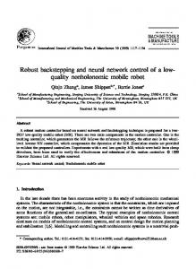
4. Simulation Results Simulations are done to illustrate the effectiveness of the robust adaptive approximate back-stepping control scheme proposed in the previous section. The vehicle model parameters are referred to in [27]. The damping of flexibility is 𝜁𝑖 = 0.02, 𝑖 = 1, 2, 3, and vibrational frequencies are 𝜔1 = 27.8944 rad/s, 𝜔2 = 76.8933 rad/s, and 𝜔3 = 150.752 6 rad/s. The aircraft is commanded to perform a cruising flight mission that the initial height is 25908 m and dynamic pressure is 95760 Pa. The initial trim conditions are designed as follows: 𝛾 = 0∘ , 𝛼 = 0.6132∘ , 𝑄 = 0∘ /s, B = 0.132 9, 𝛿𝑒 = 9.0081∘ , 𝜂1 = 1.889 m⋅kg0.5 /m0.5 , 𝜂2 = −0.028 m⋅kg0.5 /m0.5 , 𝜂3 = −0.007 323 m⋅kg0.5 /m0.5 , and 𝜂𝑖̇ = 0 m/s⋅kg0.5 /m0.5 , 𝑖 = 1, 2, 3. The reference commands of velocity and altitude are generated via the following filters:
800
0.2 ΔV (m/s)
̃ 𝑀, 𝑥̃ ∈ {𝑉, ̃ ̃ℎ, 𝛾̃, 𝛼̃, 𝑄}, ̃ do not belong to the ̃ 𝜃̃𝑓𝑥 , 𝜃̃𝑔𝑥 and Δ If 𝑥, 𝑥 ̃ compact set Ω𝑥̃ , Ω𝜃̃𝑓 , Ω𝜃̃𝑔 and ΩΔ̃ 𝑀𝑥 , respectively, 𝑊̇ ≤ 0. 𝑥, 𝑥 𝑥 𝑀 ̃ are bounded. Further, 𝜆 𝑥 also is bounded 𝜃̃𝑓𝑥 , 𝜃̃𝑔𝑥 , and Δ 𝑥 according to (66). By regulating the designed parameters, the radius of Ω𝑥̃ , Ω𝑊 ̃𝑓 , Ω𝑊 ̃𝑔 , and ΩΔ ̃ 𝑀 can be made arbitrarily 𝑥 𝑥 𝑥 small.
600 t (s)
Figure 3: Response curves of altitude and altitude tracking error (Case 1).
𝜃𝑓𝑀𝑉 = 20, 𝜃𝑔𝑀𝑉 = 50, 𝜃𝑓𝑀𝛾 = 0.01, 𝜃𝑔𝑀𝛾 = 0.2, 𝜃𝑓𝑀𝑄 = 5, and 𝜃𝑔𝑀𝑄 = 10.
4.1. Trajectory Tracking Simulation without External Disturbance. To show efficiency of the proposed control law, the following two cases are proposed. Case 1. The track height command is a square wave signal, whose amplitude Δℎ𝑐 = 1524 m and period is 600 s.
11
0.16 Φ 0.14 0.12 0.1
0
200
400
11
600 t (s)
800
1000
1200
𝛿e (∘ )
10 9 8 7
𝜂3 (ft slugs0.5 /ft)
0.18
𝜂2 (ft slugs0.5 /ft)
𝜂1 (ft slugs0.5 /ft)
Mathematical Problems in Engineering 2 1.5 1 0.5
0.02 0 −0.02 −0.04
0
200
400
600 t (s)
800
1000
1200
0
200
400
600 t (s)
800
1000
1200
0
200
400
600 t (s)
800
1000
1200
0
−0.005
0
200
400
600 t (s)
800
1000
1200
−0.01
Figure 4: Time history of fuel equivalence ratio and elevator deflection (Case 1)
Figure 6: The flexible states (Case 1).
V (m/s)
0 −0.5
0
200
400
𝛼 (∘ )
1.5
600 t (s)
800
1000
1200
0
200
400
600 t (s)
800
1000
1200
0
200
400
600 t (s)
800
1000
1200
1 0.2
0.5 0
0
200
400
600
800
1000
1200
t (s) 2 Q (∘ )
2347.8 2347.7 2347.6 2347.5 2347.4 2347.3
ΔV (m/s)
𝛾 (∘ )
0.5
0.1 0 −0.1
0 −2
0
200
400
600 t (s)
800
1000
1200
Figure 5: Response curves of flight path angle, attack angle, and pitch rate (Case 1).
Case 2. The track height command is a square wave signal, whose amplitude Δℎ𝑐 = 3048 m and period is 600 s. Time responses of velocity, altitude, flight path angle, attack angle, pitch rate, fuel equivalence ratio, elevator deflection, and flexible states in two cases are given in Figures 2–11. Time responses to altitude step change in Case 1 are presented in Figures 2–6. As shown in Figures 2 and 3, the velocity and altitude can track their commands timely and without any steady tracking errors. The control inputs and attitude angles are smooth and within their bounds, just as shown in Figures 4 and 5. The flexible states can reach equilibrium state, which can be observed from Figure 6. Time responses to altitude step change in Case 2 are presented in Figures 7–11. It can be seen from Figure 9 that the saturation occurs in elevator deflection during simulation,
Reference trajectory Tracking trajectory
Figure 7: Response curves of velocity and velocity tracking error (Case 2).
but the controller still provides a good track characteristic according to Figures 7–10. Furthermore, the flexible states also can maintain stability, which can be observed from Figure 11. 4.2. Trajectory Tracking Simulation with External Disturbance. To illustrate the robustness to external disturbance of the control laws developed herein, two vertical wind disturbances whose amplitudes are 17 m/s and 14 m/s are added to the control system in 100 s and 300 s, respectively, and the sustaining time of wind disturbance is 10 s. The additional attack angle with wind disturbance can be expressed as 𝛼𝑢 = arctan
𝑢 sin 𝛾 , 𝑉 + 𝑢 cos 𝛾
𝛼𝑤 = arctan
𝑤 cos 𝛾 , 𝑉 − 𝑤 sin 𝛾
(73)
12
Mathematical Problems in Engineering
h (m)
×104 2.9
𝛾 (∘ )
1
2.8
0 −1
2.7
0
200
400
600 t (s)
800
1000
1200
0
200
400
600 t (s)
800
1000
1200
0
200
400
600 t (s)
800
1000
1200
2.6 0
200
400
600
800
1000
1200
t (s)
𝛼 (∘ )
2
2.5
1 0
2 Δh (m)
1 2 Q (∘ )
0 −1 −2
0
200
400
600 t (s)
800
1000
−2
1200
Reference trajectory Tracking trajectory
0
Figure 10: Response curves of flight path angle, attack angle, and pitch rate (Case 2).
𝜂1 (ft slugs0.5 /ft)
Figure 8: Response curves of altitude and altitude tracking error (Case 2).
0.25
Φ 0.15 0.1 0.05
0
200
400
600 t (s)
800
1000
1200
𝜂3 (ft slugs0.5 /ft)
14 𝛿 e (∘ )
12 10 8 6
𝜂2 (ft slugs0.5 /ft)
0.2
0
200
400
600 t (s)
800
1000
1200
Figure 9: Time history of fuel equivalence ratio and elevator deflection (Case 2).
where 𝛼𝑢 and 𝛼𝑤 are horizontal additional attack angle and vertical additional attack angle, respectively; 𝑢 and 𝑤 are level wind speed and vertical wind speed, respectively. The aircraft is commanded to perform a cruising flight mission that the initial height is 25908 m and dynamic pressure is 95760 Pa. When the simulation time 𝑡 ≤ 215 s, altitude follows the step command with 50 ft/s; when the simulation time 215 s ≤ 𝑡 ≤ 355 s, altitude follows the step command with 139 ft/s. The simulation results are illustrated in Figures 12–15. It can be seen from Figure 14 that the saturation occurs in elevator deflection with wind disturbance in 100 s and 300 s, but the controller still provides a good track characteristic according to Figures 12–15, which indicate that the proposed adaptive neural back-stepping controller has a good
2 1 0
0.02 0 −0.02 −0.04
0
200
400
600 t (s)
800
1000
1200
0
200
400
600 t (s)
800
1000
1200
0
200
400
600 t (s)
800
1000
1200
0 −0.005 −0.01
Figure 11: The flexible states (Case 2).
performance on disposing input constraint under external disturbance.
5. Conclusions An adaptive neural back-stepping control design is presented in this paper for hypersonic vehicle with input constraint and uncertain aerodynamic parameters. To reduce the complexity of the controller design, the nonlinear model is divided into two subsystems, and the adaptive neural back-stepping controllers are developed for them, respectively. The neural network based radial basis function is designed to approximate the unknown system nonlinearity, which needs less knowledge of dynamic model. In order to eliminate the problem of “explosion of term,” a second-order reference model is designed for the precise estimation of the derivatives of virtual control laws. Expressly, the auxiliary systems are constructed to eliminate the saturation effect, where a novel
Mathematical Problems in Engineering
13
3200 V (m/s)
3000 2800
0.4
Φ
2600 0.2
2400 2200
0
100
0.2
200 t (s)
300
400
0
100
200 t (s)
300
400
0
100
200 t (s)
300
400
15 𝛿 e (∘ )
ΔV (m/s)
10 0
5 0
−0.2
−5 0
100
200
300
400
t (s)
Figure 14: Time history of fuel equivalence ratio and elevator deflection.
Vref V
Figure 12: Response curves of velocity and velocity tracking error. 𝛾 (∘ )
×104 4 h (m)
1 0.5 0 −0.5
0
100
200
300
400
t (s)
3.5 𝛾c 𝛾
3
0
100
300
400
0 −2 −4
0
100
200 t (s)
300
400
100
200 t (s)
300
400
5 𝛼c 𝛼
0 −5
5 0
100
200 t (s)
300
400
href h
Figure 13: Response curves of altitude and altitude tracking error.
auxiliary error compensation scheme is proposed. A comprehensive Lyapunov based stability analysis is provided to show that the control design achieves ultimate boundedness tracking for the hypersonic vehicle. Simulation results demonstrate that the proposed control strategy can provide satisfactory velocity and altitude tracking performance with input constraint and uncertain aerodynamic parameters.
Conflict of Interests The authors declare that there is no conflict of interests regarding the publication of this paper.
Q (∘ /s)
Δh (m)
10
200 t (s)
𝛼 (∘ )
2 2.5
0 −5 −10
0
Qc Q
Figure 15: Response curves of flight path angle, attack angle, and pitch rate.
Acknowledgment This work was supported by the Aeronautical Science Foundation of China (Grant no. 20120916006).
References [1] Q. Zong, Y. Ji, F. Zeng, and H. Liu, “Output feedback backstepping control for a generic Hypersonic Vehicle via small-gain
14
[2]
[3]
[4]
[5]
[6] [7]
[8]
[9]
[10]
[11]
[12]
[13]
[14]
[15]
[16]
[17]
[18]
Mathematical Problems in Engineering theorem,” Aerospace Science and Technology, vol. 23, no. 1, pp. 409–417, 2012. Q. Zong, F. Wang, B. Tian, and R. Su, “Robust adaptive dynamic surface control design for a flexible air-breathing hypersonic vehicle with input constraint and uncertainty,” Nonlinear Dynamics, vol. 78, no. 1, pp. 289–315, 2014. J. Wang, Q. Zong, R. Su, and B. Tian, “Continuous high order sliding mode controller design for a flexible air-breathing hypersonic vehicle,” ISA Transactions, vol. 53, no. 3, pp. 690– 698, 2014. C. I. Marrison and R. F. Stengel, “Design of robust control systems for a hypersonic aircraft,” Journal of Guidance, Control, and Dynamics, vol. 21, no. 1, pp. 58–63, 1998. K. P. Groves, Modelling, Simulation, and Control Design of an Air-breathing Hypersonic Vehicle, Ohio State University, Columbus, Ohio, USA, 2005. P. V. Kokotovic, “The joy of feedback: nonlinear and adaptive,” IEEE Control Systems, vol. 12, no. 3, pp. 7–17, 1992. T. Lee and Y. Kim, “Nonlinear adaptive flight control using backstepping and neural networks controller,” Journal of Guidance, Control, and Dynamics, vol. 24, no. 4, pp. 675–682, 2001. X. Bu, X. Wu, R. Zhang, Z. Ma, and J. Huang, “Tracking differentiator design for the robust backstepping control of a flexible air-breathing hypersonic vehicle,” Journal of the Franklin Institute. Engineering and Applied Mathematics, vol. 352, no. 4, pp. 1739–1765, 2015. X. Bu, X. Wu, Z. Ma, and R. Zhang, “Nonsingular direct neural control of air-breathing hypersonic vehicle via back-stepping,” Neurocomputing, vol. 153, no. 1, pp. 164–173, 2015. D.-X. Gao, Z.-Q. Sun, and J.-H. Liu, “Dynamic inversion control for a class of pure-feedback systems,” Asian Journal of Control, vol. 14, no. 2, pp. 605–611, 2012. D. Gao, Z. Sun, and B. Xu, “Fuzzy adaptive control for purefeedback system via time scale separation,” International Journal of Control, Automation and Systems, vol. 11, no. 1, pp. 147–158, 2013. M. Sharma, J. A. Farrell, M. Polycarpou et al., “Back-stepping flight control using on-line function approximation,” in Proceedings of the AIAA Guidance, Navigation, and Control Conference, Chicago, Ill, USA, August 2009. L. Fiorentini, Nonlinear adaptive controller design for airbreathing hypersonic vehicles [M.S. thesis], The Ohio State University, Columbus, Ohio, USA, 2010. B. Xu, F. Sun, H. Liu, and J. Ren, “Adaptive Kriging controller design for hypersonic flight vehicle via back-stepping,” IET Control Theory & Applications, vol. 6, no. 4, pp. 487–497, 2012. X. Bu, X. Wu, Y. Chen, and R. Bai, “Nonlinear-disturbanceobserver-based sliding mode backstepping control of hypersonic vehicles,” Control Theory & Applications, vol. 31, no. 11, pp. 1473–1479, 2014. X. W. Bu, X. Y. Wu, R. Zhang, and F. Zhu, “Design of a hyperbolic-sine-based nonlinear tracking differentiator,” Journal of Xi’an Jiaotong University, vol. 49, no. 1, pp. 107–111, 2015. X. Bu, X. Wu, Z. Ma, and Y. Zhong, “Design of a modified arctangent-based tracking differentiator,” Journal of Shanghai Jiaotong University, vol. 49, no. 2, pp. 164–168, 2015. X. Bu, X. Wu, Z. Ma, and R. Zhang, “Novel adaptive neural control of flexible air-breathing hypersonic vehicles based on sliding mode differentiator,” Chinese Journal of Aeronautics, vol. 28, no. 4, pp. 1209–1216, 2015.
[19] N. O. P´erez-Arancibia, T.-C. Tsao, and J. S. Gibson, “Saturationinduced instability and its avoidance in adaptive control of hard disk drives,” IEEE Transactions on Control Systems Technology, vol. 18, no. 2, pp. 368–382, 2010. [20] Y.-Y. Cao and Z. L. Lin, “Robust stability analysis and fuzzyscheduling control for nonlinear systems subject to actuator saturation,” IEEE Transactions on Fuzzy Systems, vol. 11, no. 1, pp. 57–67, 2003. [21] M. Chen, S. S. Ge, B. V. E. How, and Y. S. Choo, “Robust adaptive position mooring control for marine vessels,” IEEE Transactions on Control Systems Technology, vol. 21, no. 2, pp. 395–409, 2013. [22] M. Chen, S. S. Ge, and B. V. E. How, “Robust adaptive neural network control for a class of uncertain MIMO nonlinear systems with input nonlinearities,” IEEE Transactions on Neural Networks, vol. 21, no. 5, pp. 796–812, 2010. [23] D. Dai, T. Hu, A. R. Teel, and L. Zaccarian, “Output feedback synthesis for sampled-data system with input saturation,” in Proceedings of the American Control Conference (ACC ’10), pp. 1797–1802, IEEE, Baltimore, Md, USA, July 2010. [24] K. Y. Volyanskyy, W. M. Haddad, and J. M. Bailey, “Neuroadaptive output feedback control for nonlinear nonnegative dynamical systems with actuator amplitude and integral constraints,” in Proceedings of American Control Conference (ACC ’09), pp. 4494–4499, St. Louis, Mo, USA, June 2009. [25] J. Zhou, Z. T. Liu, H. Y. Su, and C. Wen, “Robust adaptive control of uncertain nonlinear systems in the presence of input saturation and external disturbance,” IEEE Transactions on Automatic Control, vol. 56, no. 7, pp. 1672–1678, 2011. [26] J. H. Huang, C. Y. Wen, W. Wang, and Z.-P. Jiang, “Adaptive stabilization and tracking control of a nonholonomic mobile robot with input saturation and disturbance,” Systems and Control Letters, vol. 62, no. 3, pp. 234–241, 2013. [27] M. A. Bolender and D. B. Doman, “Nonlinear longitudinal dynamical model of an air-breathing hypersonic vehicle,” Journal of Spacecraft and Rockets, vol. 44, no. 2, pp. 374–387, 2007. [28] Q. Zong, F. Wang, B. Tian, and R. Su, “Robust adaptive approximate backstepping control of a flexible air-breathing hypersonic vehicle with input constraint and uncertainty,” Proceedings of the Institution of Mechanical Engineers I, vol. 228, no. 7, pp. 521–539, 2014. [29] A. Serrani, A. M. Zinnecker, L. Fiorentini, M. A. Bolender, and D. B. Doman, “Integrated adaptive guidance and control of constrained nonlinear air-breathing hypersonic vehicle models,” in Proceedings of the American Control Conference (ACC ’09), pp. 3172–3177, IEEE, St. Louis, Mo, USA, June 2009. [30] A. A. Rodriguez, J. J. Dickeson, O. Cifdaloz et al., “Modeling and control of scramjet-powered hypersonic vehicles: challenges, trends, and tradeoffs,” in Proceedings of the AIAA Guidance, Navigation and Control Conference and Exhibit, Honolulu, Hawaii, USA, August 2008. [31] M. Chen, S. S. Ge, and B. V. E. How, “Robust adaptive neural network control for a class of uncertain MIMO nonlinear systems with input nonlinearities,” IEEE Transactions on Neural Networks, vol. 21, no. 5, pp. 796–812, 2010. [32] M. Chen, S. S. Ge, and B. B. Ren, “Adaptive tracking control of uncertain MIMO nonlinear systems with input constraints,” Automatica, vol. 47, no. 3, pp. 452–465, 2011.
Advances in
Operations Research Hindawi Publishing Corporation http://www.hindawi.com
Volume 2014
Advances in
Decision Sciences Hindawi Publishing Corporation http://www.hindawi.com
Volume 2014
Journal of
Applied Mathematics
Algebra
Hindawi Publishing Corporation http://www.hindawi.com
Hindawi Publishing Corporation http://www.hindawi.com
Volume 2014
Journal of
Probability and Statistics Volume 2014
The Scientific World Journal Hindawi Publishing Corporation http://www.hindawi.com
Hindawi Publishing Corporation http://www.hindawi.com
Volume 2014
International Journal of
Differential Equations Hindawi Publishing Corporation http://www.hindawi.com
Volume 2014
Volume 2014
Submit your manuscripts at http://www.hindawi.com International Journal of
Advances in
Combinatorics Hindawi Publishing Corporation http://www.hindawi.com
Mathematical Physics Hindawi Publishing Corporation http://www.hindawi.com
Volume 2014
Journal of
Complex Analysis Hindawi Publishing Corporation http://www.hindawi.com
Volume 2014
International Journal of Mathematics and Mathematical Sciences
Mathematical Problems in Engineering
Journal of
Mathematics Hindawi Publishing Corporation http://www.hindawi.com
Volume 2014
Hindawi Publishing Corporation http://www.hindawi.com
Volume 2014
Volume 2014
Hindawi Publishing Corporation http://www.hindawi.com
Volume 2014
Discrete Mathematics
Journal of
Volume 2014
Hindawi Publishing Corporation http://www.hindawi.com
Discrete Dynamics in Nature and Society
Journal of
Function Spaces Hindawi Publishing Corporation http://www.hindawi.com
Abstract and Applied Analysis
Volume 2014
Hindawi Publishing Corporation http://www.hindawi.com
Volume 2014
Hindawi Publishing Corporation http://www.hindawi.com
Volume 2014
International Journal of
Journal of
Stochastic Analysis
Optimization
Hindawi Publishing Corporation http://www.hindawi.com
Hindawi Publishing Corporation http://www.hindawi.com
Volume 2014
Volume 2014