Hindawi Publishing Corporation Mathematical Problems in Engineering Volume 2014, Article ID 357864, 10 pages http://dx.doi.org/10.1155/2014/357864
Research Article Adaptive PI-Based Sliding Mode Control for Nanopositioning of Piezoelectric Actuators Jin Li1 and Liu Yang1,2 1 2
College of Automation, Harbin Engineering University, Harbin 150001, China Department of Earth and Space Science and Engineering, York University, Toronto, ON, Canada M3J 1P3
Correspondence should be addressed to Liu Yang;
[email protected] Received 12 December 2013; Accepted 20 December 2013; Published 27 January 2014 Academic Editor: Shen Yin Copyright © 2014 J. Li and L. Yang. This is an open access article distributed under the Creative Commons Attribution License, which permits unrestricted use, distribution, and reproduction in any medium, provided the original work is properly cited. This paper proposes an adaptive proportion-integral (PI)-based sliding mode control design (APISMC) used for nanopositioning of piezoelectric actuators (PEAs). Nonlinearities, mainly hysteresis, can drastically degrade the system performance. As well as the model imperfection, hysteresis can be treated as uncertainties of the system. These uncertainties can be addressed by sliding mode control (SMC) since SMC is promising for positioning and tracking control. To further improve the response speed, suppress chattering, and reduce the steady-state error, the adaptive PI-based SMC is employed to replace the discontinuous control. Actually, the adaptive PI-based SMC offers a fast convergence of the sliding surface. Further, another advantage of the proposed controller lies in that its implementation only requires the online tuning PI parameters without acquiring the knowledge of bounds on system uncertainties. A linear second-order system is utilized as the estimated model to compensate for the process nonlinearity and estimate the control gain. The robust stability of the APISMC is proved through a Lyapunov stability analysis. Simulation results demonstrate that the modified SMC is superior to the original one for both positioning and tracking applications. Compared with the original, the proposed controller provides better performance—less chattering, faster response, and higher precision.
1. Introduction Piezoelectric actuators (PEAs) have been widely used in a variety of applications because of the advantages of its high positioning resolution, large actuating force, fast response, and lack of backlash and friction [1], for example, scanning tunneling microscopy [2, 3], adaptive optics [4], nanofabrication, and data storage [1, 5, 6]. Nevertheless, the main problems of the PEAs come from the nonlinearities attributed to hysteresis and creep when the PEAs are driven by a voltage amplifier. These nonlinearities prevent PEAs from providing the desired high-precision motion resolution and accuracy and can even lead to system instability [4, 7]. Creep can be seen as a slow drift in the PEAs displacement after responding to a sudden change in the input voltage. This causes a loss of precision when positioning is required over extended periods of time; especially, when the PEAs are applied in slow or static applications, their performances are more prominent. However, feedback techniques can be used to mitigate the creep effect.
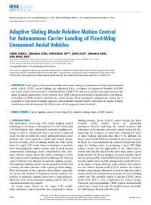
Hysteresis is a nonlinear relationship between the applied voltage and the output displacement with nonsmooth and nonmemoryless nature as well as multivaluedness and induces an open-loop positioning error as high as 10%– 15% of the PEAs travel range. Figure 1 shows an simulation observed hysteresis of the PEA model used in this research. It can be minimized by operating the PEA in a low frequency range by keeping the amplitude of the applied voltage as small as possible, for example, less than 10% of the maximal range of motion [8]. However, this restricts the usefulness of the PEAs. Alternatively, hysteresis can be significantly suppressed by operating the PEAs using a charge amplifier [1, 9–11]. Nonetheless, the charge amplifier has not been widely adopted because of its complex implementation and high cost [12]. Thus, the development of advanced controllers in order to suppress the effect of hysteresis in PEAs has drawn more attention. Various control strategies have been developed and proposed in the literature to reduce the effect of hysteresis, of which two types of control approaches are most commonly
2
Mathematical Problems in Engineering 4
3
3 Output displacement (𝜇m)
Displacement (𝜇m)
2 1 0 −1 −2 −3
2 1 0
−1 −2 −3
0
0.5
1
1.5 Time (s)
2
2.5
3
(a)
−4 −3
−2
−1 0 1 Input command (𝜇m)
2
3
(b)
Figure 1: (a) A 1-Hz input displacement signal applied to the PEA model. (b) Hysteresis loop obtained by simulation.
used in the control of PEAs. The first is the inverse-based feedforward compensation control, with the other one being some types of feedback control. In feedforward control, hysteresis is compensated using an inverse of the hysteresis model, which is commonly modeled by the Preisach model [13, 14], Prandt-Ishlinskii model [15, 16], Maxwell resistive capacitor (MRC) model [17, 18], and Bouc-Wen model [19]. However, the parameters may change with temperature and it is difficult to be obtained precisely. Considering that the modeling error, as well as the disturbance of the system, will cause the positioning and tracking to lose precision, a feedforward is often combined with feedback control [20, 21]. Additionally, taking into account that modeling the hysteresis is a complicated procedure, feedback control techniques without consideration of hysteresis have been exploited, such as PID (proportional-integral-derivative) control [22], robust control [23–26], and repetitive control [27]. Since the nonlinearity and uncertainty of the system due to hysteresis can be treated as disturbances to be suppressed, sliding mode control (SMC) has been employed due to its effectiveness and ability to deal with model imperfection and uncertainties for nonlinear systems [28–30]. SMC is a nonlinear control approach that drives the system’s state trajectory onto a specified sliding surface and maintains the trajectory on this surface for the subsequent time. However, because of the discontinuous control part in the original SMC, it may induce poor tracking performance and create undesirable oscillations in the control signal and even may excite high-frequency dynamics neglected in the course of modeling. Additionally, the original SMC, as well as the design of the boundary layer technique of SMC (SMCBL), requires the prior knowledge of bounds on system uncertainties and disturbances. However, these bounds are rarely available. To overcome these drawbacks, the adaptive PI-based control strategy is proposed instead of the discontinuous control term for the SMC in this paper as an enhanced version of the original one. There
has been a few papers using PID algorithm to replace the discontinuous term of the sliding mode control [31, 32]. The advantage of this strategy is dramatically suppressing the chattering which is not expected in practice. In [33], there exists a modified PID-based sliding mode control method. It uses adaptive laws to regulate the PID parameters online which does not need to know the knowledge of bounds on system uncertainties. In this paper, it only requires the online tuning PI parameters as an adaptive PI-based sliding mode control method. The adaptive integral component offers a fast convergence of the sliding surface and a smooth control of the PEA resulting in zero steady-state error. Here the PEA is considered as a second-order system which is hysteresis model based. A linear second-order system is employed as an estimated model to compensate for the process nonlinearity and estimate the control gain. The stability of the proposed controller is proved by using Lyapunov analysis and the positioning and tracking performance of the resulting control system is compared to that of the original SMCBL through simulations on a PEA model. This paper is organized as follows. In Section 2, the problem background is presented. In Section 3 the adaptive PI-based SMC is designed. Simulations demonstration of the proposed controller and comparison with the conventional SMCBL is shown in Section 4. Section 5 concludes this paper.
2. Problem Background A class of single input nonlinear systems with dynamic processes can be defined as 𝑥(𝑛) = 𝑓 (𝑋, 𝑡) + 𝑏 (𝑋, 𝑡) 𝑢 (𝑡) , 𝑇
(1)
where 𝑋 = [𝑥, 𝑥,̇ . . . , 𝑥(𝑛−1) ] is the state vector, 𝑥(𝑡) is the output state, and 𝑢(𝑡) is the control input. The superscript 𝑛 on 𝑥(𝑡) signifies the order of differentiation [33].
Mathematical Problems in Engineering
3 Furthermore, define a time-varying sliding surface 𝑠(𝑡), where
Consider the PEA as a second-order system: 𝑥̈ (𝑡) = 𝑓 (𝑋, 𝑡) + 𝑏 (𝑋, 𝑡) 𝑢 (𝑡) ,
(2)
where 𝑓(𝑋, 𝑡) and 𝑏(𝑋, 𝑡) are in general nonlinear and poŝ 𝑡) and ̂𝑏(𝑋, 𝑡), sibly time-varying and are estimated as 𝑓(𝑋, respectively. The estimation uncertainty Δ𝑓(𝑋, 𝑡) on 𝑓(𝑋, 𝑡) is assumed to be bounded by a function 𝐹(𝑋, 𝑡), such that Δ𝑓 (𝑋, 𝑡) = 𝑓 (𝑋, 𝑡) − 𝑓̂ (𝑋, 𝑡) ≤ 𝐹 (𝑋, 𝑡) .
(3)
The control gain 𝑏(𝑋, 𝑡) is unknown but of known bounds (the control gain could possibly be nonlinear time-varying or state-dependent) [34]: 0 < 𝑏min (𝑋, 𝑡) ≤ 𝑏 (𝑋, 𝑡) ≤ 𝑏max (𝑋, 𝑡) .
(4)
Since the control input enters multiplicatively in the dynamics, it is natural to choose the estimation ̂𝑏(𝑋, 𝑡) of gain 𝑏 as the geometric mean of the above bounds: ̂𝑏 (𝑋, 𝑡) = √𝑏 (𝑋, 𝑡) 𝑏 (𝑋, 𝑡). min max
(5)
̂𝑏 (𝑋, 𝑡) ≤ 𝛽 (𝑋, 𝑡) , 𝑏 (𝑋, 𝑡)
𝑛−1 𝑑 + 𝜆) 𝑒 (𝑡) 𝑑𝑡
𝑠 (𝑡) = 𝑒 ̇ (𝑡) + 𝜆𝑒 (𝑡) .
(12)
Given the initial condition of (10), the problem of tracking 𝑥(𝑡) = 𝑥𝑑 (𝑡) is equivalent to that of remaining on the surface 𝑠(𝑡) for all 𝑡 > 0. Thus, making the sliding surface 𝑠(𝑡) ≡ 0 represents a linear differential equation whose ̇ = 0. unique solution is 𝑒(𝑡) = 0 and 𝑒(𝑡) Theorem 1. For a single-input second-order nonlinear system given by (1), with the sliding surface defined by (12), both the system stability and tracking convergence are guaranteed if the control law is given by 𝑢 (𝑡) − 𝑘 (𝑋, 𝑡) sgn (𝑠 (𝑡))] , 𝑢 (𝑡) = ̂𝑏(𝑋, 𝑡)−1 [̂
(13)
where sgn(⋅) represents the signum function and
𝑘 (𝑋, 𝑡) = 𝐹 (𝑋, 𝑡) + 𝜂, (6)
(11)
and 𝜆 is a strictly positive constant. Here 𝑛 = 2, so
𝑢̂ (𝑡) = −𝑓̂ (𝑋, 𝑡) + 𝑥𝑑̈ (𝑡) − 𝜆𝑒 ̇ (𝑡) ,
The bounds of (4) can then be written in the form 𝛽(𝑋, 𝑡)−1 ≤
𝑠 (𝑡) = (
(14)
where 𝜂 is a positive switching gain and 𝑘(𝑋, 𝑡) satisfies 𝑘 (𝑋, 𝑡) ≥ 𝛽 (𝑋, 𝑡) (𝐹 (𝑋, 𝑡) + 𝜂) + (𝛽 (𝑋, 𝑡) − 1) |̂ 𝑢 (𝑡)| . (15)
where 𝛽 (𝑋, 𝑡) = √
𝑏max (𝑋, 𝑡) . 𝑏min (𝑋, 𝑡)
(7)
Since the control law will be designed to be robust to the bounded multiplicative uncertainty equation (6), 𝛽 can be called the gain margin of the design. Note that 𝛽 may be timevarying or state-dependent and that it also has 𝛽(𝑋, 𝑡)
−1
𝑏 (𝑋, 𝑡) ≤ ≤ 𝛽 (𝑋, 𝑡) . ̂𝑏 (𝑋, 𝑡)
(16)
So its time derivative can be obtained as 𝑉̇ = 𝑠𝑠.̇
(17)
By taking the time derivative of both sides of (12), the term 𝑠 ̇ can be generated
3.1. Sliding Mode Controller Design. To design a sliding mode controller (SMC), an error coordinate is defined as (9)
where 𝑥𝑑 (𝑡) represents the desired position trajectory, and for the tracking task to be achievable using a finite control 𝑢(𝑡), the initial desired position 𝑥𝑑 (0) must be such that 𝑥 (0) = 𝑥𝑑 (0) .
1 𝑉 = 𝑠2 . 2
(8)
3. Controller Design
𝑒 (𝑡) = 𝑥 (𝑡) − 𝑥𝑑 (𝑡) ,
Proof. To have a concise manner of representation, in the rest of this paper the state vector 𝑋 and the time variable 𝑡 will be omitted. Considering the positive definite Lyapunov function,
(10)
In a second-order system, for example, position or velocity cannot “jump”, so that any desired trajectory feasible from time 𝑡 = 0 necessarily starts with the same position and velocity as those of the plant. Otherwise, tracking can only be achieved after a transient [34].
𝑠 ̇ = 𝜆𝑒 ̇ + 𝑒 ̈ = 𝜆𝑒 ̇ + 𝑥̈ − 𝑥𝑑̈ = 𝜆𝑒 ̇ − 𝑥𝑑̈ + 𝑓 + 𝑏̂𝑏−1 [̂ 𝑢 − 𝑘 sgn (𝑠)]
(18)
̂ + (1 − 𝑏̂𝑏−1 ) (𝜆𝑒 ̇ − 𝑥̈ ) = (𝑓 − 𝑏̂𝑏−1 𝑓) 𝑑 − 𝑏̂𝑏−1 𝑘 sgn (𝑠) . If the gain 𝑘 is designed to meet the condition 𝑘 ≥ 𝛽 (𝐹 + 𝜂) + (𝛽 − 1) |̂ 𝑢| ≥ ̂𝑏𝑏−1 𝐹 + 𝜂̂𝑏𝑏−1 + ̂𝑏𝑏−1 − 1 𝑓̂ − 𝑥𝑑̈ + 𝜆𝑒̇
≥ ̂𝑏𝑏−1 𝑓 − 𝑓̂ + (̂𝑏𝑏−1 − 1) (−𝑥𝑑̈ + 𝜆𝑒)̇ + 𝜂̂𝑏𝑏−1 ,
(19)
4
Mathematical Problems in Engineering
then, considering (18) and (19), one can derive that 𝑉̇ = 𝑠𝑠 ̇ ̂ + (1 − 𝑏̂𝑏−1 ) (𝜆𝑒 ̇ − 𝑥̈ )] − 𝑏̂𝑏−1 𝑘 |𝑠| = 𝑠 [(𝑓 − 𝑏̂𝑏−1 𝑓) 𝑑 ̂ + (1 − 𝑏̂𝑏−1 ) (𝜆𝑒 ̇ − 𝑥̈ )] ≤ 𝑠 [(𝑓 − 𝑏̂𝑏−1 𝑓) 𝑑 ̇ 𝑠 − 𝜂 |𝑠| − 𝑏̂𝑏−1 [̂𝑏𝑏−1 𝑓 − 𝑓̂ + (̂𝑏𝑏−1 − 1) (−𝑥𝑑̈ + 𝜆𝑒)] ̂ + (1 − 𝑏̂𝑏−1 ) (𝜆𝑒 ̇ − 𝑥̈ )] ≤ 𝑠 [(𝑓 − 𝑏̂𝑏−1 𝑓) 𝑑
3.2. Adaptive PI-Based Sliding Mode Controller Design. It is proposed to overcome the problems associated with SMC and SMCBL by introducing a sliding mode controller based on an adaptive PI design (APISMC). The original SMC structure is retained in the proposed controller, except that the discontinuous switching control input is replaced with a continuous input determined by an adaptive PI algorithm. The PI controller in the APISMC considers the sliding surface function 𝑠 as the input and the resulting overall control law of the proposed controller is 𝑢 − 𝑢PI ) , 𝑢 = ̂𝑏−1 (̂
̂ + (1 − 𝑏̂𝑏−1 ) (𝜆𝑒 ̇ − 𝑥̈ )] 𝑠 − 𝜂 |𝑠| − [(𝑓 − 𝑏̂𝑏−1 𝑓) 𝑑
where 𝑢̂(𝑡) is the same as that defined earlier in (13) and
= −𝜂 |𝑠| .
𝑢PI = 𝑘𝑝 𝑠 + 𝑘𝑖 ∫ 𝑠,
(20) This shows that the controller satisfies the sliding condition and the sliding surface will be reached in a finite time [34]. Thus, the sliding variable 𝑠 → 0 as 𝑡 → ∞. According to the definition of (12), if 𝑠 → 0, then 𝑒 → 0 and 𝑒 ̇ → 0; hence 𝑥 → 𝑥𝑑 and 𝑥̇ → 𝑥𝑑̇ as 𝑡 → ∞. Therefore, the control law ensures both the stability of the system and the convergence of the motion tracking. Control laws which satisfy the sliding condition of (20) lead to good tracking in the presence of the model uncertainty and system disturbances but are discontinuous across the sliding surface 𝑠(𝑡). Due to the discontinuity, chattering may occur in the control input. Generally, chattering is highly undesirable, since it involves extremely high control activity, and may excite high-frequency dynamics neglected in the course of modeling. In general, chattering must be eliminated for the controller to perform properly. To alleviate the chattering phenomenon, the boundary layer technique (SMCBL) is adopted by replacing the signum function in (13) with the saturation function 𝑠 { , { {Φ 𝑠 sat ( ) = { { Φ {sgn ( 𝑠 ) , Φ {
𝑠 if < 1, Φ 𝑠 if ≥ 1, Φ
(22)
(23)
where 𝑘𝑝 and 𝑘𝑖 are the PI proportional gain and integral gain, respectively. Assumption 2. For a given proportional gain 𝑘𝑝 , there exists an integral gain 𝑘𝑖∗ so that the stability of the control system is satisfied; that is, with 𝑢PI = 𝑘𝑝 𝑠 + 𝑘𝑖∗ ∫ 𝑠, the condition 𝑠𝑠 ̇ ≤ −𝜂|𝑠| holds. Define the PI integral parameter error as ̃𝑘 = 𝑘 − 𝑘∗ . 𝑖 𝑖 𝑖
(24)
Theorem 3. For a single-input second-order nonlinear system given by (1), with the sliding surface defined by (12), both the system stability and tracking convergence are guaranteed if the control law is given by (22) and the variable integral error 𝑘𝑖∗ is estimated online according to the adaptive rule: ̇ 𝑘̃𝑖 = 𝛿𝑠 ∫ 𝑠,
(25)
where 𝛼 is a positive constant. Proof. Considering the positive definite Lyapunov function, 𝑉=
(21)
where the positive constant Φ represents the boundary layer thickness, which ensures that 𝑠 is always bounded by Φ. In the selection of the parameter Φ, a tradeoff between the chattering and tracking error will occur. The controller with saturation function does reduce the degree of chattering in the control input; however, the chattering effect will still exist, as shown later in Section 4. At the same time, the attractive SMC feature of insensitivity to uncertainties and disturbances is lost in SMCBL because of the control forcing the states into the region bounded with the bounding layers instead of onto the sliding surface. As well as the original SMC, the design of SMCBL also requires prior knowledge of the bounds of uncertainties and disturbance. However, these bounds are rarely available in practice.
1 2 1 ̃2 (𝑠 + 𝑘𝑖 ) . 2 𝜎
(26)
So its time derivative can be obtained as 1 ̇ 𝑉̇ = 𝑠𝑠 ̇ + ̃𝑘𝑖 𝑘̃𝑖 . 𝜎
(27)
By modifying the control input 𝑢 in (23), the term 𝑠 ̇ can be generated: 𝑠 ̇ = 𝜆𝑒 ̇ + 𝑒 ̈ = 𝜆𝑒 ̇ + 𝑥̈ − 𝑥𝑑̈ = 𝜆𝑒 ̇ − 𝑥𝑑̈ + 𝑓 + 𝑏̂𝑏−1 [̂ 𝑢 − 𝑢PI ] ̂ + (1 − 𝑏̂𝑏−1 ) (𝜆𝑒 ̇ − 𝑥̈ ) = (𝑓 − 𝑏̂𝑏−1 𝑓) 𝑑 − 𝑏̂𝑏−1 (𝑘𝑝 𝑠 + 𝑘𝑖 ∫ 𝑠) .
(28)
Mathematical Problems in Engineering
5
Then substituting (28), (24), and (25) into (27), one can derive that 𝑉̇ = 𝑠𝑠 ̇ ̂ + (1 − 𝑏̂𝑏−1 ) (𝜆𝑒 ̇ − 𝑥̈ ) = 𝑠 [ (𝑓 − 𝑏̂𝑏−1 𝑓) 𝑑 1 ̇ − 𝑏̂𝑏−1 (𝑘𝑝 𝑠 + 𝑘𝑖 ∫ 𝑠)] + ̃𝑘𝑖 𝑘̃𝑖 𝜎 ̂ + (1 − 𝑏̂𝑏−1 ) (𝜆𝑒 ̇ − 𝑥̈ ) = 𝑠 [ (𝑓 − 𝑏̂𝑏−1 𝑓) 𝑑
Table 1: Parameters of the PEA with Bouc-Wen model. Parameter 𝑛 𝜉 𝜔𝑛 𝐾 𝛼 𝛽 𝛾
Value 1 1.2315 × 10⁴ 1.2225 × 10⁶ 1.7339 × 10⁻⁶ 0.3575 0.0364 0.0272
the piezoelectric actuator as a second-order system with nonlinear hysteresis, which can be written as
− 𝑏̂𝑏−1 (𝑘𝑝 𝑠 + 𝑘𝑖∗ ∫ 𝑠)] 1 ̇ − 𝑠𝑏̂𝑏−1 (𝑘𝑖 ∫ 𝑠 − 𝑘𝑖∗ ∫ 𝑠) + ̃𝑘𝑖 𝑘̃𝑖 𝜎 1 ̇ ≤ −𝜂 |𝑠| − 𝑏𝑏 𝑘𝑖 𝑠 ∫ 𝑠 + ̃𝑘𝑖 𝑘̃𝑖 𝜎 ̂ −1 ̃
1 ̇ = −𝜂 |𝑠| − ̃𝑘𝑖 (𝑏̂𝑏−1 𝑠 ∫ 𝑠 − 𝑘̃𝑖 ) 𝜎 = −𝜂 |𝑠| , (29) where 𝛿 = 𝜎𝑏̂𝑏−1 . This shows that the controller satisfies the sliding condition and the sliding surface will be reached in a finite time. Thus, the sliding variable 𝑠 → 0 as 𝑡 → ∞. According to the definition of (12), if 𝑠 → 0, then 𝑒 → 0 and 𝑒 ̇ → 0; hence 𝑥 → 𝑥𝑑 and 𝑥̇ → 𝑥𝑑̇ as 𝑡 → ∞. Additionally, the integral gain of PI can be automatically tuned to satisfy both the reachability and stability conditions. Therefore, the control law ensures both the stability of the system and the convergence of the motion tracking. The PI control proportional term drives the variable 𝑠 to a neighborhood around zero, and the integral action forces the convergence to zero. The integral term plays an important role in ensuring that the states move onto the sliding surface. It also provides a smooth control signal and better performance in implementation, yielding less chattering and faster convergence.
4. Simulation Results In this section, the modified APISMC is validated and compared with the original SMC through simulations. 4.1. PEA Model. For the purpose of simulation, a Bouc-Wen model for hysteresis is employed in this work. In view of the fact that the smaller the system uncertainty, the better the motion tracking performance, the hysteresis is modeled in this research even though a sliding mode-based controller can be designed without modeling the hysteresis. The BoucWen model has already been verified that it is suitable to describe the hysteresis loop of PEAs [35]. Considering
𝑥̈ + 2𝜉𝜔𝑛 𝑥̇ + 𝜔𝑛2 𝑥 = 𝜔𝑛2 (𝐾𝑢 − ℎ) ,
(30)
̇ 𝑛, ℎ̇ = 𝛼𝑑𝑢̇ − 𝛽 |𝑢|̇ ℎ|ℎ|𝑛−1 − 𝛾𝑢|ℎ|
(31)
where 𝜉, 𝜔𝑛 , 𝐾, and ℎ are the damping ratio, the natural frequency, the gain of the second-order system, and the nonlinear hysteresis, respectively; 𝑑 is the piezoelectric coefficient, 𝑢 denotes the input voltage, and ℎ indicates the hysteretic loop in terms of displacement whose magnitude and shape are determined by parameters 𝛼, 𝛽, and 𝛾 and the order 𝑛, where the order 𝑛 governs the smoothness of the transition from elastic to plastic response. For the elastic structure and material, 𝑛 = 1 is assigned in (31) as usual. These parameters used in this paper are calculated through simulations from [36, 37] and the values of these parameters are shown in Table 1. In this paper, 𝑓̂ is considered as the process nonlinearity compensation term, −𝑥𝑑̈ + 𝜆𝑒 ̇ is considered as the linear state feedback term, and 𝑘𝑝 𝑠 + 𝑘𝑖 ∫ 𝑠 is considered to replace the discontinuous switching control term. Here using the linear second-order system [38] as the estimated model, which is 𝑥̈ + 2𝜉𝜔𝑛 𝑥̇ + 𝜔𝑛2 𝑥 = 𝐾𝜔𝑛2 𝑢, 𝑓̂ = −2𝜉𝜔𝑛 𝑥̇ − 𝜔𝑛2 𝑥,
(32)
the estimation ̂𝑏 of the control gain 𝑏 can be obtained as ̂𝑏 = 𝑘𝜔2 . 𝑛
(33)
The proposed adaptive PI-based SMC controller consists of a linear estimation term 𝑓̂ to compensate for the process nonlinearity, a linear feedback term −𝑥𝑑̈ + 𝜆𝑒 ̇ to control the process with a specified performance, and a PI control term which allows the overall system to be more robust and to drive the process states onto the sliding surface. 4.2. Step Responses. First, the transient response capabilities of the controllers are examined. For comparison, the simulation responses to a step signal were performed by employing the traditional SMCBL and the proposed APISMC controller. The controller parameters are shown in Table 2, and the results for steps of different amplitudes are depicted in Figure 2 and tabulated in Table 3 for a clear comparison.
6
Mathematical Problems in Engineering 2.5 1.2
2 Displacement (𝜇m)
Displacement (𝜇m)
1 0.8 0.6 1.002
0.4
1.5 1
1
0.2
0.998 0 −0.2
2.04 2.02 2 1.98 1.96
0.5 0
7 0
0.002
0.004 0.006 Time (s)
8
9
10 ×10−3 0.01
0.008
1 −0.5
0
0.002
0.004 0.006 Time (s)
2 0.008
3 ×10⁻³ 0.01
Reference SMC APISMC
Reference SMC APISMC (a)
(b)
5
3.5 3
4 Displacement (𝜇m)
Displacement (𝜇m)
2.5 2 1.5 1
2
1
0.5 0 −0.5
3
0 0
0.002
0.004 0.006 Time (s)
0.008
0.01
0
0.002
0.004 0.006 Time (s)
0.008
0.01
Reference SMC APISMC
Reference SMC APISMC (c)
(d)
Figure 2: Simulation responses to step signals with amplitudes of (a) 1 𝜇m; (b) 2 𝜇m; (c) 3 𝜇m; and (d) 4 𝜇m.
Table 2: Parameters of the implemented controllers. Controller SMC
APISMC
Parameter 𝜆 𝑘 Φ 𝑘𝑝
Value 10000 3 × 10⁷ 0.01 2 × 10⁵
𝑘𝑖 initial 𝜆 𝛿
1 80000 0.01
It is observed from the steady-state results that the APISMC controller provides a smooth control with less chattering and better convergence performance. Specifically, it can produce a faster response with a smaller settling time. It is also found that a faster response can be obtained using SMCBL as well; however, it is at the expense of chattering. As shown in Figure 2 and Table 3, it can be observed that although the proposed controller gives the transient response with some overshoot (there is no overshoot in SMC implementation), the response is over 3 times quicker than that of the conventional SMCBL.
Mathematical Problems in Engineering
7 Table 3: Control performance in step tracking.
Performance (with different amplitudes) 1% settling time (ms) Overshoot
SMC 1 𝜇m 2.92 0
2 𝜇m 3.00 0
3 𝜇m 3.20 0
4 𝜇m 3.40 0
5
APISMC 2 𝜇m 3 𝜇m 0.80 0.90 6.84% 3.85%
1 𝜇m 0.70 13.09%
4 𝜇m 1.00 2.72%
0.01
4 Tracking error (𝜇m)
Displacement (𝜇m)
0.005 3 2 1
0
−0.005 0 −1
0
0.1
0.2
0.3
0.4
−0.01
0.5
0
0.1
0.2
Time (s)
0.3 Time (s)
0.4
0.5
0.3
0.4
0.5
Desired Actual (b)
(a)
0.01
5
Tracking error (𝜇m)
Displacement (𝜇m)
4 3 2 1
0.005
0
−0.005 0 −1
0
0.1
0.2
0.3
0.4
0.5
Time (s)
−0.01
0
0.1
0.2 Time (s)
Desired Actual (c)
(d)
Figure 3: Experimental results of response to a 20 Hz sinusoidal signal: (a)-(b) tracking results of SMC and (c)-(d) tracking results of APISMC.
4.3. Sinusoidal Trajectory. The performances for tracking a sinusoidal waveform of 4 𝜇m peak-to-peak (p-p) amplitude using two controllers are compared in Figures 3 and 4 and described in Table 4. It can be seen from the trajectories and tracking errors that the APISMC can track the sinusoidal trajectory more precisely than the SMCBL. The SMCBL produces a maximum error of 0.0069 𝜇m at 20 Hz and
0.0230 𝜇m at 50 Hz. The proposed APISMC has an error of 5.5204 × 10⁻⁴ 𝜇m at 20 Hz and 0.0029 𝜇m at 50 Hz. 4.4. Discussions on Control Performance. From the simulation results, it can be concluded that the APISMC is superior to the traditional SMCBL in both set-point control and
Mathematical Problems in Engineering 5
0.03
4
0.02 Tracking error (𝜇m)
Displacement (𝜇m)
8
3 2 1
0.01 0 −0.01 −0.02
0 −1
0
0.1
0.2
0.3
0.4
−0.03
0.5
0
0.1
0.2
Time (s)
0.3
0.4
0.5
0.3
0.4
0.5
Time (s)
Desired Actual (b)
5
0.03
4
0.02 Tracking error (𝜇m)
Displacement (𝜇m)
(a)
3 2 1 0 −1
0.01 0 −0.01 −0.02
0
0.1
0.2
0.3
0.4
0.5
Time (s)
−0.03
0
0.1
0.2 Time (s)
Desired Actual (c)
(d)
Figure 4: Experimental results of response to a 50 Hz sinusoidal signal: (a)-(b) tracking results of SMC and (c)-(d) tracking results of APISMC.
tracking control. In the step input simulations, the proposed controller enables a quicker response without much overshoot, and, in particular, it eliminates the chattering without a steady-state error. The APISMC is also more suitable for tracking control due to its smaller tracking error in the sinusoidal simulations.
5. Conclusions In this paper, a new adaptive PI-based sliding mode controller is proposed for piezoelectric actuators. In order to get better motion tracking performance, the hysteresis model is considered in the PEA model for simulation. A linear secondorder system is utilized as the estimated model to compensate
for the process nonlinearity and estimate the control gain of the modified controller. The step response simulation results illustrate that the modified controller can speed up the transient response with some overshoot as compared to the original one. Additionally, it provides a smooth control and better performance in the control implementation yielding less chattering and faster convergence. The sinusoidal motion tracking simulations show that the proposed controller can improve the tracking performance with a smaller tracking error than that of the original SMCBL. Based on this control strategy, the design of the controller is simple to drive the PEAs. Robust stability of the proposed controller is guaranteed under the nonlinear uncertainties and model errors.
Mathematical Problems in Engineering
9
Table 4: Performance of the controllers with sinusoidal signal. Performance (with different frequencies) 5 (HZ) 10 (HZ) 20 (HZ) 50 (HZ) 100 (HZ)
SMC RMSE (𝜇m) 9.7542 × 10⁻⁷ 1.3951 × 10⁻⁶ 6.3364 × 10⁻⁶ 1.7269 × 10⁻⁴ 0.0021
In the future, we are interested in extending our research to fault detection and fault tolerant control of systems using piezoelectric actuators basing on related results [39–44].
Conflict of Interests The authors declare that there is no conflict of interests regarding the publication of this paper.
Acknowledgment The authors would like to acknowledge the financial support of the National Key Scientific Instrument and Equipment Development Projects, China, through Grant no. 2012YQ04014010.
References [1] S. Devasia, E. Eleftheriou, and S. O. R. Moheimani, “A survey of control issues in nanopositioning,” IEEE Transactions on Control Systems Technology, vol. 15, no. 5, pp. 802–823, 2007. [2] D. Croft, G. Shedd, and S. Devasia, “Creep, hysteresis, and vibration compensation for piezoactuators: atomic force microscopy application,” in Proceedings of the American Control Conference, pp. 2123–2128, June 2000. [3] S. O. R. Moheimani, “Accurate and fast nanopositioning with piezoelectric tube scanners: emerging trends and future challenges,” Review of Scientific Instruments, vol. 79, no. 7, Article ID 071101, 2008. [4] H. Song, G. Vdovin, R. Fraanje, G. Schitter, and M. Verhaegen, “Extracting hysteresis from nonlinear measurement of wavefront-sensorless adaptive optics system,” Optics Letters, vol. 34, no. 1, pp. 61–63, 2009. [5] K. W. Chan and W.-H. Liao, “Precision positioning of hard disk drives using piezoelectric actuators with passive damping,” in Proceedings of the IEEE International Conference on Mechatronics and Automation (ICMA ’06), pp. 1269–1274, June 2006. [6] A. Sebastian, A. Pantazi, G. Cherubini, E. Eleftheriou, M. A. Lantz, and H. Pozidis, “Nanopositioning for probe storage,” in Proceedings of the American Control Conference (ACC ’05), pp. 4181–4186, June 2005. [7] H. J. M. T. A. Adriaens, W. L. De Koning, and R. Banning, “Modeling piezoelectric actuators,” IEEE/ASME Transactions on Mechatronics, vol. 5, no. 4, pp. 331–341, 2000. [8] K. Leang, Q. Zou, and S. Devasia, “Feedforward control of piezoactuators in atomic force microscope systems,” IEEE Control Systems, vol. 29, no. 1, pp. 70–82, 2009.
APISMC Max.E (𝜇m) −0.0038 0.0043 0.0069 0.0230 0.0690
RMSE (𝜇m) 4.8415 × 10⁻⁹ 1.8005 × 10⁻⁸ 1.5046 × 10⁻⁷ 4.3371 × 10⁻⁶ 5.2509 × 10⁻⁵
Max.E (𝜇m) 9.7061 × 10⁻⁵ 1.9198 × 10⁻⁴ 5.5204 × 10⁻⁴ 0.0029 0.0103
[9] G. M. Clayton, S. Tien, A. J. Fleming, S. O. R. Moheimani, and S. Devasia, “Inverse-feedforward of charge-controlled piezopositioners,” Mechatronics, vol. 18, no. 5-6, pp. 273–281, 2008. [10] J. Minase, T.-F. Lu, B. Cazzolato, and S. Grainger, “A review, supported by experimental results, of voltage, charge and capacitor insertion method for driving piezoelectric actuators,” Precision Engineering, vol. 34, no. 4, pp. 692–700, 2010. [11] Y. T. Ma, L. Huang, Y. B. Liu, and Z. H. Feng, “Note: creep character of piezoelectric actuator under switched capacitor charge pump control,” Review of Scientific Instruments, vol. 82, no. 4, Article ID 046106, 2011. [12] G. Y. Gu, M. J. Yang, and L. M. Zhu, “Real-time inverse hysteresis compensation of piezoelectric actuators with a modified prandtl-ishlinskii model,” Review of Scientific Instruments, vol. 83, no. 6, Article ID 065106, 2012. [13] M.-J. Jang, C.-L. Chen, and J.-R. Lee, “Modeling and control of a piezoelectric actuator driven system with asymmetric hysteresis,” Journal of the Franklin Institute, vol. 346, no. 1, pp. 17–32, 2009. [14] L. Liu, K. Tan, S. Chen, C. Teo, and T. Lee, “Discrete composite control of piezoelectric actuators for high-speed and precision scanning,” IEEE Transactions on Industrial Informatics, vol. 9, no. 2, pp. 859–868, 2013. [15] D. Pesotski, H. Janocha, and K. Kuhnen, “Adaptive compensation of hysteretic and creep non-linearities in solid-state actuators,” Journal of Intelligent Material Systems and Structures, vol. 21, no. 14, pp. 1437–1446, 2010. [16] B. Mokaberi and A. A. G. Requicha, “Compensation of scanner creep and hysteresis for AFM nanomanipulation,” IEEE Transactions on Automation Science and Engineering, vol. 5, no. 2, pp. 197–206, 2008. [17] T.-J. Yeh, H. Ruo-Feng, and L. Shin-Wen, “An integrated physical model that characterizes creep and hysteresis in piezoelectric actuators,” Simulation Modelling Practice and Theory, vol. 16, no. 1, pp. 93–110, 2008. [18] L. Juh´asz, J. Maas, and B. Borovac, “Parameter identification and hysteresis compensation of embedded piezoelectric stack actuators,” Mechatronics, vol. 21, no. 1, pp. 329–338, 2011. [19] Y. C. Huang and D. Y. Lin, “Ultra-fine tracking control on piezoelectric actuated motion stage using piezoelectric hysteretic model,” Asian Journal of Control, vol. 6, no. 2, pp. 208–216, 2004. [20] G. Song, J. Zhao, X. Zhou, and J. A. De Abreu-Garc´ıa, “Tracking control of a piezoceramic actuator with hysteresis compensation using inverse Preisach model,” IEEE/ASME Transactions on Mechatronics, vol. 10, no. 2, pp. 198–209, 2005. [21] C.-J. Lin and S.-R. Yang, “Precise positioning of piezo-actuated stages using hysteresis-observer based control,” Mechatronics, vol. 16, no. 7, pp. 417–426, 2006. [22] H. G. Xu, T. Ono, and M. Esashi, “Precise motion control of a nanopositioning PZT microstage using integrated capacitive
10
[23]
[24]
[25]
[26]
[27]
[28]
[29]
[30]
[31]
[32]
[33]
[34] [35]
[36]
[37]
[38]
[39]
Mathematical Problems in Engineering displacement sensors,” Journal of Micromechanics and Microengineering, vol. 16, no. 12, Article ID 2747, 2006. A. Sebastian and S. M. Salapaka, “Design methodologies for robust nano-positioning,” IEEE Transactions on Control Systems Technology, vol. 13, no. 6, pp. 868–876, 2005. M. Boukhnifer and A. Ferreira, “H∞ loop shaping bilateral controller for a two-fingered tele-micromanipulation system,” IEEE Transactions on Control Systems Technology, vol. 15, no. 5, pp. 891–905, 2007. J. Dong, S. M. Salapaka, and P. M. Ferreira, “Robust control of a parallel-kinematic nanopositioner,” Journal of Dynamic Systems, Measurement and Control—Transactions of the ASME, vol. 130, no. 4, pp. 0410071–04100715, 2008. T. W. Seo, H. S. Kim, D. S. Kang, and J. Kim, “Gain-scheduled robust control of a novel 3-DOF micro parallel positioning platform via a dual stage servo system,” Mechatronics, vol. 18, no. 9, pp. 495–505, 2008. C.-Y. Lin and P.-Y. Chen, “Precision tracking control of a biaxial piezo stage using repetitive control and double-feedforward compensation,” Mechatronics, vol. 21, no. 1, pp. 239–249, 2011. H. C. Liaw, B. Shirinzadeh, and J. Smith, “Enhanced sliding mode motion tracking control of piezoelectric actuators,” Sensors and Actuators A, vol. 138, no. 1, pp. 194–202, 2007. H. C. Liaw, B. Shirinzadeh, and J. Smith, “Sliding-mode enhanced adaptive motion tracking control of piezoelectric actuation systems for micro/nano manipulation,” IEEE Transactions on Control Systems Technology, vol. 16, no. 4, pp. 826–833, 2008. J.-C. Shen, W.-Y. Jywe, C.-H. Liu, Y.-T. Jian, and J. Yang, “Sliding-mode control of a three-degrees-of-freedom nanopositioner,” Asian Journal of Control, vol. 10, no. 3, pp. 267–276, 2008. Y. Cao and X. Chen, “Integrated inversion-feedforward and pidbased-sliding-mode-control for piezo301 electric actuators,” in Proceedings of the American Control Conference (ACC ’12), pp. 869–874, IEEE, 2012. J. Peng and X. Chen, “Integrated pid-based sliding mode state estimation and control for piezoelectric actuators,” IEEE/ASME Transactions on Mechatronics, no. 99, pp. 1–12, 2012. M. Li, F. Wang, and F. Gao, “Pid-based sliding mode controller for nonlinear processes,” Industrial and Engineering Chemistry Research, vol. 40, no. 12, pp. 2660–2667, 2001. J. J. E. Slotine, W. Li et al., Applied Nonlinear Control, vol. 199, Prentice hall New Jersey, 1991. T. S. Low and W. Guo, “Modeling of a three-layer piezoelectric bimorph beam with hysteresis,” Journal of Microelectromechanical Systems, vol. 4, no. 4, pp. 230–237, 1995. Y. Li and Q. Xu, “Adaptive sliding mode control with perturbation estimation and PID sliding surface for motion tracking of a piezo-driven micromanipulator,” IEEE Transactions on Control Systems Technology, vol. 18, no. 4, pp. 798–810, 2010. L. Yang and J. Shan, “Sliding mode control with pi-based saturation for piezoelectric actuators,” submitted to Smart Meterials and Structure. J. W. Li, X. B. Chen, and W. J. Zhang, “A new approach to modeling system dynamics-in the case of a piezoelectric actuator with a host system,” IEEE/ASME Transactions on Mechatronics, vol. 15, no. 3, pp. 371–380, 2010. E. Balaban, A. Saxena, P. Bansal, K. F. Goebel, P. Stoelting, and S. Curran, “A diagnostic approach for electro-mechanical actuators in aerospace systems,” in Proceedings of the IEEE Aerospace Conference, IEEE, March 2009.
[40] B. Hasch, O. Lindenborn, and R. Nordmann, “Model-based fault detection on a rotor in an actively supported bearing using piezoelectric actuators and the fxlms-algorithm,” in Motion and Vibration Control, pp. 123–132, Springer, 2009. [41] S. Yin, H. Luo, and S. Ding, “Real-time implementation of faulttolerant control systems with performance optimization,” IEEE Transactions on Industrial Electronics, vol. 61, no. 5, 2013. [42] S. Yin, S. X. Ding, A. H. Abandan Sari, and H. Hao, “Data-driven monitoring for stochastic systems and its application on batch process,” International Journal of Systems Science, vol. 44, no. 7, pp. 1366–1376, 2013. [43] S. Yin, S. X. Ding, A. Haghani, H. Hao, and P. Zhang, “A comparison study of basic data-driven fault diagnosis and process monitoring methods on the benchmark tennessee eastman process,” Journal of Process Control, vol. 22, no. 9, pp. 1567–1581, 2012. [44] S. Yin, G. Wang, and H. R. Karimi, “Data-driven design of robust fault detection system for wind turbines,” Mechatronics, 2013.
Advances in
Operations Research Hindawi Publishing Corporation http://www.hindawi.com
Volume 2014
Advances in
Decision Sciences Hindawi Publishing Corporation http://www.hindawi.com
Volume 2014
Journal of
Applied Mathematics
Algebra
Hindawi Publishing Corporation http://www.hindawi.com
Hindawi Publishing Corporation http://www.hindawi.com
Volume 2014
Journal of
Probability and Statistics Volume 2014
The Scientific World Journal Hindawi Publishing Corporation http://www.hindawi.com
Hindawi Publishing Corporation http://www.hindawi.com
Volume 2014
International Journal of
Differential Equations Hindawi Publishing Corporation http://www.hindawi.com
Volume 2014
Volume 2014
Submit your manuscripts at http://www.hindawi.com International Journal of
Advances in
Combinatorics Hindawi Publishing Corporation http://www.hindawi.com
Mathematical Physics Hindawi Publishing Corporation http://www.hindawi.com
Volume 2014
Journal of
Complex Analysis Hindawi Publishing Corporation http://www.hindawi.com
Volume 2014
International Journal of Mathematics and Mathematical Sciences
Mathematical Problems in Engineering
Journal of
Mathematics Hindawi Publishing Corporation http://www.hindawi.com
Volume 2014
Hindawi Publishing Corporation http://www.hindawi.com
Volume 2014
Volume 2014
Hindawi Publishing Corporation http://www.hindawi.com
Volume 2014
Discrete Mathematics
Journal of
Volume 2014
Hindawi Publishing Corporation http://www.hindawi.com
Discrete Dynamics in Nature and Society
Journal of
Function Spaces Hindawi Publishing Corporation http://www.hindawi.com
Abstract and Applied Analysis
Volume 2014
Hindawi Publishing Corporation http://www.hindawi.com
Volume 2014
Hindawi Publishing Corporation http://www.hindawi.com
Volume 2014
International Journal of
Journal of
Stochastic Analysis
Optimization
Hindawi Publishing Corporation http://www.hindawi.com
Hindawi Publishing Corporation http://www.hindawi.com
Volume 2014
Volume 2014