University of Kent at Canterbury. {D.H.Akehurst, J.Derrick, A.G.Waters}@kent.ac.uk. Abstract. Distributed System design is a highly complicated and non-trivial ...
Addressing Computational Viewpoint Design D.H.Akehurst, J.Derrick, A.G.Waters University of Kent at Canterbury {D.H.Akehurst, J.Derrick, A.G.Waters}@kent.ac.uk Abstract Distributed System design is a highly complicated and non-trivial task. The problem is characterised by the need to design multi-threaded, multi-processor, and multimedia systems. Design frameworks such as Open Distributed Processing (ODP), the ITU/ISO standard, define a number of viewpoints from which the design of a distributed system should be approached. To use the framework, a design language for each of these viewpoints must be defined. This paper defines a computational viewpoint language based on the Unified Modelling Language (UML) and Component Quality Modelling Language (CQML). The use of this approach to provide the ODP viewpoint languages enables standard UML tools to be used as part of an ODP compliant design process; and in addition, it will potentially enable the use of Meta Object Facility (MOF) based generation tools for constructing tool support for our language.
1. Introduction The formation of the ‘Global Grid Forum’ and the consequent interest in “research, development, deployment, and support activities related to high-capability distributed software systems” [1]
reinforces the need for a significant improvement in the capabilities of tools and support environments for the development of distributed systems. The technologies of the internet, CORBA, web services, etc. provide the capability to build such systems. However, there is not the necessary level of support at the design stage to enable systems analysts and designers to manage the inherent complexity. The work contained in this paper forms part of a project – Design Support Environments for Distributed Systems (DSE4DS [2]), which aims to extend facilities for the design of multimedia distributed systems, to ensure that they can meet the needs of complex systems that include the use of stream communication, multicasting and Quality of Service (QoS) constraints. The work will augment the design environment with descriptions in sufficiently precise notations to enable
assessments of designs to be made based on fitness for purpose, performance and functionality. As a basis for the definition of a distributed system, we target the definitions contained in the ITU/ISO standard framework for Open Distributed Processing (ODP). The telecommunications industry has long been investigating the problems of designing distributed systems and has standardised on a number of issues. The Reference Model for ODP (RM-ODP) [3] addresses the design of distributed systems; and related standards [4, 5] address specifically the issue of stream communication and the definition of the quality at which the computing system components provide their services – commonly known as Quality of Service (QoS). The work reported in this paper looks at enabling tool support for the design languages involved, in particular this paper describes a design method and language to support design within the computational viewpoint – one of the five viewpoints defined by the ODP standard, with the aim of using this as input to a tool generation suite. An aspect of our approach to the design of computing systems is to make use of the current common and best practises and tools that support the design of the types of distributed multimedia systems in which we are interested; this approach should result in widely understood specifications and gain us maximum support from existing design tools. Currently, the Unified Modelling Language (UML [6]) is by common practise a clear contender for the design language of choice. However, although having significant community and tool support, it does not provide a means to address some of the issues relevant to distribution and multimedia; to support the design of such systems we make use of the RM-ODP. The RM-ODP does not prescribe the use of any particular concrete notation; hence where appropriate we make use of notations taken from the UML, e.g. for the specification of behaviour we use the UML State Diagram [6] notation. We are aware that the definition of the UML is surrounded by arguments involving its ambiguity and lack of precision. Hence, we aim in this paper to provide an ODP Computational Viewpoint language that will be supported by tools that implement the UML language;
however, the provided language must be well defined and based on the concepts from the RM-ODP specifications. We argue that by defining the ODP viewpoint languages in this manner, we gain three benefits: 1. Tool support for the languages, by utilising the wide range of tool support given to the UML; 2. Machine readable specifications, produced by the tools, in the UML standard XMI format, enabling further tools to be developed that read the design models, and give back appropriate feedback; 3. Tool generation facilities, made possible due to the meta-modelling approach to language specification (see explanation of Kent Modelling Framework (KMF) section 2.1). The Computational Viewpoint Language defined here builds on the work started in [7], taking the opportunity to introduce additional facility for modelling multicast features. The language draws on the notations used in [8] and the language defined in [9]. The rest of the paper is organised as follows. Section 2 introduces ODP, describing in particular the concepts that are required in a computational viewpoint specification language. This section also describes the language definition architecture (i.e. a means to define our computational viewpoint language) we will use and introduces the definition of a concrete language for the Computational Viewpoint. Section 3 contains the specification of a Near Video on Demand system as an example to illustrate our method and language for computational viewpoint design and discusses the differences between our language and the UML. Section 4 reviews related work and discusses tool support for our language, illustrating how tools can be used to provide support for the computational language. Section 7 concludes the paper, including an indication of future work to be carried out in relation to that presented here.
2. A Computational Viewpoint Language The ODP framework proposes a multi-paradigm specification approach for the design of distributed systems by identifying five separations of concern and addresses the design of the system from each. Different languages may be used for each separation of concern providing the benefit that the relative strengths of different specification languages can be exploited. In ODP terminology these five separations of concern are named viewpoints. The RM-ODP defines five viewpoints: enterprise, information, computational, engineering and technology; further information regarding both the reference model and its approach to using viewpoints can be found in [3, 10, 11]. The language definition approach proposed in this paper is explored within the scope of the
A Language Definition Specification Language
Configuration Language
Semantic Mapping
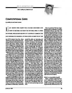
Figure 1 - Architecture for a language definition computational viewpoint, although we believe it is also applicable to the other viewpoints. The computational viewpoint is concerned with the identification of distributable components (objects) and their interaction points (interfaces). The viewpoint addresses the specification of the behaviour of identified objects; the specification of the signatures of the interfaces through which they interact; the specification of templates from which such components can be instantiated; and the specification of any constraints under which the objects must operate. The mechanism by which distributed communication is achieved is not addressed in this viewpoint (that is part of the purpose of the engineering viewpoint), i.e. distribution transparency is assumed. Part 3 of the RM-ODP [3] defines the concepts and structuring rules that define an ‘abstract’ language for each of the viewpoints. The definitions must be considered abstract, as there is no defined (concrete) syntax specified for any of the viewpoint languages. The description of concepts and rules can be modelled using the OMG’s MOF [12] concepts of class, association, generalization etc. These are a subset of the specification concepts found in the more commonly used UML. The following two subsections firstly describe the language definition architecture that we will use and then illustrate its use by showing parts of the definition of our computational viewpoint language. The full definition can be found at [13].
2.1 A Language Definition Architecture Many of the approaches to computational viewpoint design propose the use of existing languages such as LOTOS [14] or Z [15]. This approach enables the reuse of existing tools and reuse of existing experience that designers might have with that language. However, whichever existing language is used the approach invariably requires a mapping between that language and the concepts of the computational viewpoint. This mapping is often defined informally; often requires the
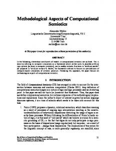
use of many constructs of the language to define a single concept of the Computational Viewpoint; and often is unable to specify some of the Computational Viewpoint concepts either at all or in an intuitive manner. To improve upon this, our approach is to design a bespoke Computational Viewpoint language that includes all of the appropriate concepts required by the Computational Viewpoint definition. The drawback of our approach would seem to be an inability to make use of existing experience and tools. Hence, we form two additional requirements for the language: a) that it is similar to an existing and widely used language (where possible); and b) that we must be able to use tools for that similar language to define specifications in our Computational Viewpoint language. As outlined previously, we aim to make use of the work related to the UML and its community in order to take advantage of its tool support and wide acceptance. In addition there is a UML related modelling architecture [16, 17] with tool support [18] that can be used for the definition of visual languages and the generation tools supporting that language. This architecture views a language as consisting of three primary packages that define the abstract syntax, semantics and semantic domain of a language, see Figure 1. In addition four other packages are used to define a concrete syntax for both the abstract syntax and semantic domain, Figure 2. The RM-ODP partitions its definitions is a similar manner, although using different names Specification Concepts (rather than Abstract Syntax) and Basic Modelling Concepts (rather than Semantic Domain). We believe that the RM-ODP names are more appropriate, better conveying a descriptive meaning of what is inside the packages. (In particular we feel that the name ‘Semantic Domain’ carries alternative meanings and context that do not quite apply here.) As the terms ‘model’ and ‘modelling’ are heavily used within the context of the UML, we use the name Configuration Concepts to replace the RM-ODP name of Basic Modelling Concepts. In addition to defining a model of the concepts for specification and for configuration we also specify models for a concrete syntax to enable Specification Language
visualisation of such concepts. Finally the key part of the architecture is the facility to specify mappings between the various models. The technique and details of defining these mappings is more fully described in [19, 20]. To define the mapping we specify relations between elements from each of two models; e.g. between elements from the concrete syntax model and the configuration concepts model. For each relation we specify the domain and range as a set of instances from each of the two related models and define a matching condition that defines whether an element from one model should be related to an element from the other. The following section includes examples to illustrate this. The Kent Modelling Framework (KMF) [18] gives us a tool set that supports this language definition architecture and enables automatic generation of tools that support the defined language. KMF provides a mechanism to generate a tool implementation from a UML model, including execution of Object Constraint Language (OCL) [6] expressions within the model. The generated tool includes a repository for populating the model; a basic GUI for viewing and manipulating the population; and facility to check and execute OCL constraints and expressions. In anticipation of the results from the KMF project, we choose to specify our language in a manner that enables us to make use of the KMF tool-generation tools. In the mean time, we specify a set of stereotypes that enable us to use make use of existing UML tools. The concrete syntax to concept mappings define a method to visualise expressions in each of the specification and configuration languages. Additionally we specify a mapping between the specification and configuration concepts that enables us to verify whether or not a particular configuration conforms to a particular specification. The facilities of the KMF framework and tools mean that having fully defined the models and mappings, we can generate tools to support the language. Additionally, the runtime OCL evaluation feature of KMF enables the generated tools to perform the conformance verification between a configuration and a specification.
Configuration Language
Concrete Syntax
Specification Concepts
Concrete ↔ SC Mapping
Concrete Syntax
Configuration Concepts
Concrete ↔ Configuration Mapping
Figure 2 - Architecture for Concrete Syntax Definitions
Configuration
interface
Interface
0..* 0..* object
CompObject
interface 2 binding
Primitive Binding
Figure 4 – Computational Objects
2.2 A Computational Configuration Language Figure 4 shows a simplified definition of the concepts for defining a computational system configuration (the full definition is tool large to describe here and can be found at [13]). Such a configuration consists of computational objects, interfaces and primitive bindings. Figure 3 shows the model of a concrete syntax for visualizing computational configurations. The syntax consists of lines, circles, oblongs and T-bars. Circles and T-bars have labels. (An example use of the syntax is shown in Figure 6.) These two figures show the language concepts and visualization concepts of a computational language for defining system configurations. To complete the definitions a mapping is required as the final step in defining the language. Figure 5 illustrates the mapping relationships for the configuration language. The definitions of the domain, range and matching condition are specified using the OCL in the context of the aggregations (labelled ‘a’ and ‘b’) that specify one relation as a sub-relation of another. They are placed in this context so that it is possible to reuse the specification of a relation (although this facility is not illustrated by the current example). The OCL for these mappings is give below: context a domain: config.object range: diagram.elements->select( el | el.oclIsKinfOf(Circle)) match: object.name = circle.label
label : String
label : String
label : String
Figure 3 – Concrete Syntax Concepts context b domain: object.interfaces range: circle.lineEnds.owner->select( el | el.oclIsKindOf(TBar)) match: interface.name = tBar.label
The same approach is used to define a specification language for defining object templates and interface signatures. An example of this language is shown in Figure 7. In addition we have defined a set of mapping relations between the specification concepts and the configuration concepts. This enables us to check whether or not a particular configuration conforms to the template and signature specifications.
3. A Near Video on Demand System This section presents the computational viewpoint design of an example system. It demonstrates our method for constructing computational viewpoint designs and illustrates the computational viewpoint design languages. The example system is a Near Video on Demand (nVoD) System. Users of the system instantiate a browser object and connect to a service manager. They then request a particular film, causing a video window to be created for the user. The window is added to a group of windows receiving the video stream for the requested film. At the designated showing time, the film is played and streamed to all users in the appropriate group. The system contains multi-media, multicast, and group features, all of which can be handled by the computational
Figure 5 – Concrete Syntax to Configuration Concepts Mapping
viewpoint design language. We start with a snapshot of the system, which gives an indication of the primary distributable components composing the system and the interfaces required to connect them. From the snapshot we identify and specify the computational object templates and interface signatures of the system. For each computational object we subsequently provide a behaviour specification. Finally we specify environment contracts for each computational object in the form of some QoS constraints. The design details are described in the following subsections.
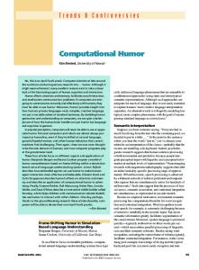
3.1 System Snapshot The first stage in our design approach is to create one or more system snapshots in the form of configuration diagrams (i.e. using the configuration language discussed above). This follows an object-oriented design methodology and helps to identify the types of object and interface that we need to create. An aspect of a computational viewpoint specification is the decomposition of the system into distributable objects that interact at interfaces. A computational object, which may be a composition of two or more other objects, is a unit of distribution and management that encapsulates behaviour [3]. In particular, computational objects are not instances of classes, as is the case in Object Oriented (OO) languages [11]. To avoid confusion with the word object, which is a ‘reserved’ word in the UML, we shall use the term Computational Object. Figure 6 depicts a computational viewpoint snapshot of our example system. Circles depict computational objects; there are three of these – manager, film1 and film2. The ‘stacked’ circles depict a group of computational objects; there are three groups indicated – vidWins1, vidWins2 and browsers. The computational objects film1 and film2 transmit video frames. The frames are transferred via binding objects to the receiver computational object groups – vidWins1 and vidWins2. Binding objects are distinguished from computational objects by illustrating them as elongated circles. manager : Service Manager
service
vsCtrl
film1
vidWins1
: VideoStream
3.2 Template and Signature Specifications browsers : Browser
vsCtrl
film2
u
vidWins2
: VideoStream videoTrans
service
videoRec
videoTrans
videoRec
Interfaces are illustrated using ‘T’ shapes, attached to a circle to indicate that the computational object (depicted by the circle) offers that particular interface. The role of the interface (producer/consumer, initiator/responder or client/server) is indicated by the direction and style of an arrow placed near the interface (as suggested in [8]). Bound interfaces are either connected via an irregularly dashed line (e.g. vsCtrl and service) or placed head to head (e.g. videoTrans, videoRec). The identification policy for objects and interfaces is similar to the approach used in UML object diagrams, computational objects and interfaces are identified by either or both of an ‘instance name’ and a ‘template name’ separated by a colon and underlined. Where bound interfaces are close together we omit naming both interfaces separately and distinguish between them using their role. The scope of an interface name is with respect to the computational object supporting that interface; hence interface names can be repeated within the scope of a snapshot. In this snapshot the two bindings are labelled with only the template name (see following section); the film objects and vidWins group objects are labelled with only an instance name (as are the interfaces); and the manager object and browsers group are labelled with both. The film computational objects emit video frames to the video bindings across the bound videoTrans stream interfaces. The receiving vidWins computational objects receive the video frames from the bindings at the bound videoRec stream interfaces. The service interfaces are operational interfaces and the vsCtrl interfaces are signal interfaces. The two interfaces ui and display attached to the browser objects are for interaction with the user input/output devices. As an alternative Concrete Syntax for these configuration diagrams we can use standard UML object diagrams (if a bespoke configuration diagram editor is unavailable). Computational Objects and Interfaces are both shown using the UML notation for an object. These UML objects should be stereotyped in order to distinguish between the representations of an interface from that of a computational object and to distinguish between different types of interface and computational object. UML ‘links’ are use to show connectivity between interfaces and computational object, and to show bindings between interfaces.
display
Figure 6 Computational Viewpoint snapshot illustrating the nVod system
The snapshot discussed in the previous subsection indicates the kinds of component needed in order to build the system. The next step is to fully specify those components in order to obtain reusable and detailed definitions of the aggregated parts of the system. From a computational viewpoint, the necessary specifications
«CompObjectTemplate»
ScheduledShowing
videoTrans
«consumer»
«StreamInterfaceSignature»
VideoInterface
«producer»
«CompObjectTemplate»
videoRec
VideoWindow
video : VideoFlow videoTrans
videoRec 0..*
«consumer»
«OperationInterfaceSignature»
DisplayInterface
«producer»
displayProg(fs : Set(FilmDescription) «SignalInterfaceSignature»
VSControlInterface join(vw:VideoInterface) : void leave(vw: VideoInterface) : void
«responder»
«StreamBindingObjectTemplate»
VideoStream
vsCtrl
display «client» «CompObjectTemplate»
Browser 0..* vsCtrl «initiator»
«OperationInterfaceSignature»
ServiceInterface «CompObjectTemplate»
ServiceManager
service «server»
getProgramme : Set( FilmDescription ) service selectToView( f : FilmDescription, vw : VideoInterface ) : void
«client»
«client»
ui «OperationInterfaceSignature»
InputInterface select(f : FilmDescription enterServiceURL(s:String)
Figure 7 Computational Template Diagram for the nVoD system include the definition of computational object templates, interface signatures, and the relationships between them. Since the UML provides a rich set of notations for capturing various aspects of computing systems, the ODP community has shown extensive interest in using parts of the UML to specify various parts of ODP designs [21-24]. However, the ODP concept of an object is not entirely compatible with the UML (and other) Object Oriented (OO) concept of an object. There are two subtle differences: 1) An ODP class is a set of entities that satisfy a type (i.e. a specification of how to classify objects), where as a UML class is the specification of how to construct an object; and 2) An interface supported by an ODP object provides a communications port, whereas a UML interface is a type classifier. In UML the class tends to be the focus of modelling, an object simply being an instance of a class. In ODP, the object itself is the focus of modelling; object instantiation is through a defined object template, rather than a class. The word class in the ODP context refers to the set of all entities that satisfy some type. So in ODP we can talk of a class of objects of type X, a class of interfaces of type Y or a class of templates of type Z. A type in ODP refers to a predicate, a set of conditions to classify an element of the system and which can be evaluated for all elements. An identifying feature of classes in ODP is that an ODP class, being a set, can be empty, i.e. nothing satisfies a given type, though it may later have members. On the other hand, templates are patterns of feature. In particular, an interface signature (template) defines the type of the interface and the interactions that may occur across that
interface. For each interaction type, the interface template defines the name and type of the interaction, the types of the parameters, the directionality and the exceptions raised. As a result, the normal UML concept of class relates more closely to the RM-ODP concept of a template. The relationship between objects and interfaces in the UML world is one of realization. A UML interface defines a particular set of features; to realize an interface, an object (defined by a UML class definition) implements the defined set of features. I.e. with respect to an interface, the features are abstract definitions, which are only ‘made real’ by an object. Within the ODP, interfaces are more of a first class entity; ODP objects offer a number of interfaces, through which interactions, both incoming and outgoing, occur. The same interface signature may be instantiated and offered by an object multiple times – offering the same set of interactions to multiple different peers. A particular point to note is that both input and output communications require an interface in the ODP world – unlike the UML, which only facilitates the specification of incoming communications; there is no means to explicitly specify what outgoing operations an object may call. A consequence of these differences is that we cannot use UML class diagrams “as is” to model the structure of distributed systems within our approach. The semantics of a UML class and its relationships are not wholly compatible with the ODP semantics of templates. However, given that the UML allows us to ‘stereotype’ its design concepts, enabling us to effectively define our own concepts, we do so. Thus we reuse the notation of UML class diagrams as a notation for the specification language
of computational viewpoint templates. This both, gives us an appropriate notation, and allows reuse of existing UML tools, for the specification of computational viewpoint specifications. The UML concept of a class is similar to the ODP notion of a template (and signature) we define stereotypes of the UML class to enable definition of the ODP concepts of: computational object template; stream, operational and signal binding object template; reactive object template; and stream, operational and signal interface signature. UML allows us to define icons related to each stereotype, so we associate an appropriate icon with each stereotype label. The concrete notation is that of UML class diagrams, with each component showing its appropriate stereotype by either or both of a label or icon. As discussed above, this gives us a language and notation suitable for defining the computational viewpoint of an ODP system, which is (hopefully) familiar to UML designers; easily used; and provided with tool support from many standard UML tools. Figure 7 defines a template diagram for the computational snapshot shown in Figure 6. Both computational object template and interface signatures are depicted using the notation for UML classes, distinguished using stereotypes. To aid the distinction, computational object and binding object templates are shaded, whereas interface signatures are not. The stereotype of interface signatures distinguishes (textually) between operations, stream and signal signatures. The iconic notation for the templates is included in the top right corner of the boxes as an additional visual aid to distinguish between objects, interfaces and bindings. The relationship between a computational object template and the interfaces that its instances may offer is defined using stereotyped UML associations. The stereotype of the association defines the role in which the object may offer instances of the interface signature; the association end name gives a navigation name for the object to refer to the interface. Each interface instance may be offered by only one object; hence the object end of the association is defined to be an aggregation (using a black diamond). Where an interface signature may be used to bind to a group of objects, we allow the UML multiplicity notation to be used on the end of the association near the interface, to indicate that a specific number (or many) interface instances may be created (e.g. the «producer» aggregation between VideoStream and VideoInterface). The UML ‘realization’ dashed-line arrow is a possibility as an alternative notation to the aggregation; this would be more inline with the UML notation for relating classes to interfaces. However, standard UML tools are unlikely to enable that addition of multiplicities to such relationships, disabling the facility to specify groups; thus we choose the aggregation relationship as our preference.
3.3 Behaviour After defining the object templates and the interfaces they may support, it is necessary to define the behaviour of the objects and the interactions that occur across the interfaces. This subsection firstly describes our adopted approach to specifying behaviour and subsequently illustrates the techniques by defining the behaviour of the ServceManager and Browser objects. As stated in the introduction, one of our requirements is to use common design practices; following this directive we look to the UML for a notation that enables the specification of state-based behaviour. The UML defines a particular variant of state and transition based behaviour, based on (a subset of) the formalism of Statecharts [25], and renamed State Diagrams within the context of the UML. A state diagram represents the behaviour of entities capable of dynamic behaviour by specifying its response to the receipt of event instances. A state diagram consists of states and transitions. A state is a condition during the life of an object or an interaction, during which it satisfies some condition, performs some action, or waits for some event. A state is normally depicted as a rectangle with rounded corners, although special types of state are depicted in other ways. A transition is a relationship between two states indicating that an instance in the first state will enter the second state and perform specific actions when a specified event occurs provided that certain guard conditions are satisfied. A transition is shown as a solid line originating from the source state and terminated by an arrow on the target state; a transition is typically labelled with a string that has the following general format: ‘[’ ‘]’ ‘/’
Where event-signature describes an event with its arguments, guard-condition is a Boolean expression written in terms of parameters of the triggering event and attributes of the object whose behaviour is described by the state machine. The action-expressions are executed if and when the transition fires (i.e. the source state is active, the event occurs and the guard evaluates to true). Actions are expressions that either: 1) Alter or access the local state of the object; 2) Instantiate interfaces to be offered by the object; or 3) Cause an interaction at a specified interface. An action must be executed entirely before any following actions are considered – i.e. actions are considered atomic. Within our usage of State Diagrams, events are caused by the receipt of signals at interfaces offered by the object. These are either: directly by receiving a signal sent to a responder signal interface; by receiving an operation call at a server operational interface; or by receiving a
ServiceManager let e = service.getProgramme() / e.source.Return_getProgramme (programmeList)
Waiting
service.selectToView(film, vw) / let ctrl = shows.get(film), ctrl.join(vw)
Figure 8 packet or frame at a consumer stream interface. The event name and parameters are taken from the respective interface signature and is clarified by the name of the interface instance with respect to the object offering it. State diagrams also allow hierarchical nesting of states; this enables complex behaviour to be specified in a concise manner. Sub-states are either single state diagrams in which contained states are ‘or’-states in that one or other is active; or alternatively sub-states can be concurrent whereby both sub-states are active and generally further refined to a sub state. There are also four special types of state (known in the UML as pseudo states). These are: the initial state, where the behaviour starts, depicted as a filled circle with a single outgoing transition; the final state, where the behaviour terminates, depicted as a filled circle inside a hollow circle; the choice state, causing dynamic evaluation of guards to determine the behavioural path, depicted as a hollow circle; and the junction state, which enables multiple transitions to be chained or merged together. Pseudo states are not assumed to be stable – i.e. the state machine should not ‘wait’ for an event to occur within a pseudo state. These different types of state map to some of the behavioural actions defined in the RM-ODP. The other ODP actions are supported by specific keywords or by using a ‘virtual’ node management function interface that provides the required behaviour. The example diagrams of Figure 8 and Figure 9 show behaviour specifications for ServiceManager and Browser objects. The service manager has a ready or Waiting state from which it provides its services of either returning the offered programme of films or registering a user’s interest in a particular film. The upper transition is fired by the event getProgramme received at the service interface. The event is assigned to the name e so that it can be referenced by the following action. There is a single action on this transition, which retrieves a reference to the client interface that initiated the operation call (e.source). The action causes the return signal of the operation call to be
sent (Return_getProgramme(…)), passing the return parameter consisting of the programme listing (retrieved from some internal state of the service manager object – not modelled here). The lower transition is fired by a call to the selectToView operation on the service interface. Parameters film and vw are passed with the operation call and hence are present in the event. There are two actions in caused by the transition; the first retrieves the value of a VSControlInteface interface for the selected film (from some unmodelled internal state of the object) and assigns the retrieved interface reference the name ctrl. The second action sends a join signal to the retrieved interface, which should cause the passed video window interface reference parameter, vw, to be added to the group of computational object interface that receive the selected film. The behaviour specification for the browser objects, shows a connected and unconnected state. The browser moves into a connected state when the user has specified the service manger to which the browser should connect. The transition is split to facilitate reuse of the connection actions, when a user specifies connection to a different manger; there are three actions involved. The first makes use of the ‘node management function’ bind that forms a binding between two interfaces. The other two actions retrieve the programme of films and display them to the user. When connected, a user of the browser can select to view a particular film. The event ui.select(film) detects this and invokes actions to firstly create a video window object and secondly pass the appropriate film description and interface reference of the video window on to the service manager.
3.4 Environment Contracts – QoS Specification The previous subsections have defined the structure, templates and functional behaviour of the system. Now we address the specification of non-functional aspects of the system by defining some QoS constraints. The ODP Browser
Unconnected
ui.enterServiceURL(s) /
ui.enterServiceURL(s) /
/ bind(service, s) let p = service.GetProgramme(), display.displayProg(p)
Connected Waiting
ui.select (film) / let vw = create VideoWindow clientServiceInterface.selectToView(film, vw.videoRec)
Figure 9
standard defines the concept of an environment contract. This is a contract between an object and its environment, i.e. all other object with which it interacts. As interactions occur across interfaces, environment contacts for an object generally involve one or more interfaces. A QoS constraint is one such example of an environment contract. Such a constraint involves two parts: 1) Requirements of the object by the environment, known as obligations; and 2) Requirements of the environment by the object, known as expectations. The relationship between these two parts states that provided the expectations are met (by the environment) the obligations will be met (by the object). There is currently no clear contender for a most commonly used (de facto) QoS language. Many have been proposed [9, 26-29]; one that we have found to be most suited to our design approach, partly due to its association with the OCL and UML, is the Component Quality Modelling Language (CQML) [30, 31]. CQML is a lexical language for QoS specification and has been developed to explicitly include as many features as possible [9]. We have found the language to be expressive, very useable and easily integrated with our other UML based languages within the ODP framework. There are many possible QoS characteristics that could be constrained, [32] lists those identified by the ITU. For the purpose of this paper we look at three stream and time related characteristics – latency, anchored jitter and throughput. Latency is the amount of time between two events (e.g. time between sending a frame and receiving it); throughput is the rate of occurrence of events (e.g. the rate of flow of frames); and anchored jitter is a variation in nominal throughput. CQML facilitates the definition of quality characteristics such as latency, throughput and anchored jitter in terms of the history of events at a particular interface. The following CQML statements define these characteristics in terms of the events occurring at each interface involved in the constraint. The semantics define that each flow of an interface instance contains a historical sequence of events. This is essentially provision of the ‘Event Notification Function’, defined by the RMODP [3], which requires event histories to be made available. quality_characteristic throughput( duration : Integer, flow : Flow ) { domain: increasing numeric integer [0..) eventsPerDuration; values: flow.events->select(e | flow.events->last.time - e.time > duration )->size }
This definition defines the characteristic named throughput. The characteristic takes two parameters, the
duration over which the throughput is constrained, and the particular flow of an interface to which the constraint is applied. The first part of the characteristic (domain) defines the type of value constrained by the characteristic and the units to be used. The values part is an OCL expression that defines the value of the constraint in terms of the parameters. This particular characteristic gives increasing positive integers and is calculated by counting the number of events whose time stamp is within duration milliseconds of the last event. quality_characteristic latency( src : Flow, tgt : Flow ) { domain: decreasing numeric milliseconds; values: let tgt_evt = tgt.events->last let src_evt = src_events->any(e | tg_evt.id = e.id ) in tgt_evt.time – src_evt.time }
This latency characteristic defines latency to be the time between the last two corresponding events from the source and target flows. Constraints regarding particular characteristics are formed in CQML by specifying quality statements, these are grouped to form QoS specifications on particular objects or object templates as QoS Profiles. A QoS profile includes statements for both expectations and obligations; each expectation or obligation is an expression referring to one or more quality statements. The quality statements enable reuse of QoS specifications across multiple QoS profiles. A quality statement contains the conjunction of a number of sub expressions that constrain a variety of quality characteristics. Each quality characteristic is defined by an OCL expression that (in the case of latency, anchored jitter and throughput) references the associated event histories. To enable quality characteristics to be generalised and reused, they can be defined with specific parameters. Given a set of pre-defined quality characteristics (throughput, anchoredJitter and latency) the QoS specifications associated with the VideoStream Template defined in Figure 7 (defining templates for the system illustrated in Figure 6) can be specified and explained as follows. The video binding from film to video window is specified to provide a through frame rate of no less than 25 fps with a latency of between 40 and 60 milliseconds (ms) so long as it receives an input frame rate of no less than 25 fps. This is expressed in CQML as follows: QosProfile for VideoBinding { exp: quality { throughput(1000, videoTrans.video)>=25; }; obl: videoRec->forAll( vr | quality { throughput(1000, vr.video) >= 25; latency(videoTrans.video, vr.video).maximum = 60; latency(videoTrans.video, vr.video).minimum = 40; }; }
The above QoS Profile, defined for the VideoBinding template, defines one expectation, that there should be at least 25 events received every second (1000 ms) at the ‘video’ VidowFlow part of the consumer interface videoTrans. It also defines that for all of the videoRec interfaces the binding is obliged to provide at least 25 frames every second (fps) from the VideoFlow (named ‘video’) part of the VideoInterface signature, supported by the binding in the role of a producer. The particular VideoFlows on which the constraints are placed is navigated to using the association end names of the associations relating object templates to interface signatures. Additionally there are constraints between consumer and producer VideoFlows that specify the maximum and minimum latency that should occur for a frame passing through the binding. We have extended the CQML language to allow OCL quantification over collections of interfaces in order that we can support the specification of quality constraints over groups. This completes the computational viewpoint design. A number of iterations through this process may be required as filling out each stage may prompt a designer to add or change information initially entered during a previous stage. However, by deciding on the information to be entered into the design at each of these stages (configuration, templates, behaviour, and environment contracts) we complete a computational viewpoint design. This design can subsequently be used to populate model checking and verification tools to provide feed back about the design. Other aspects of the DSE4DS project address the provision of such tools, based on computational viewpoint designs consisting of the above described information.
4. Tool Support and Related Work As discussed earlier, the primary motivations for specifying out language using this approach is to facilitate use of the KMF tool generator to provide tools for our language. Currently the KMF tool will: • Provide a repository for storing and manipulating specifications in our language. • Enable (OCL) constraints to be checked in order to affirm that a valid specification has been formed. • Provide persistent storage of the specification as an XML document; enabling saving and loading of Computational Viewpoint specifications. • Support the implementation of mappings between two models, enabling constraints to be evaluated that report whether or not a mapping is valid. • Provide transformation code that will either generate one model from the other or reconcile two partially consistent models.
The KMF tool will not yet generate editors for the concrete syntax – these must be provided separately. One option, currently in use, is to use a UML tool along with the defined stereotypes and provide a mapping between the UML meta-model and our Computational Viewpoint language model. Using a UML tool we can save the specification as an XML representation of the model (using the defined UML encoding – XMI). This can be loaded into the tool generated by KMF and by activating a model transformation be used to populate our abstract Computational Viewpoint language model. We hope to provide a bespoke concrete syntax editor within the next few months. The design approach presented in this paper is an evolution of our earlier work [7, 33]. Previously we proposed an approach that used the UML in a stricter fashion for the structural and behavioural design and the language QL for specifying QoS. The strict use of UML caused designs to be expressed in a manner that made them hard to read and lengthy to write. Additionally, the QoS language QL does not integrate well with UML – as described in [33]. To improve upon this, we have adopted a more flexible approach to using UML, providing stereotypes to enable design using specifically the concepts defined in the RM-ODP. This approach has also been used in [34] although they do not use the RM-ODP terminology and in [21] and [23] which stereotype UML elements to define a language for creating ODP Enterprise specifications. There is also the EDOC profile for UML [35]; this is very large, but does not address sufficiently facilities for specifying computational viewpoint languages. Besides, for the reasons outlined above, we prefer a newly defined language rather than an adaptation of a language designed with other specification goals in mind. We have allowed our design approach to be influenced by non-UML based methods such as the work at Lancaster [28] and in particular the methods proposed by Blair and Stefani in [8]. Our approach to QoS specification uses the Aagedal’s CQML language [9] which he has shown to be well integrated with and useable in the context of UML based designs [30]. There are other approaches to the specification of QoS, discussed in [9] and in [36]. The approach taken by [37] and defined in the new CORBA 3 standard [38] is to use extensions of the OMG’s Interface Definition Language (IDL) for defining QoS, however we consider this to be a technology specific approach and prefer the use of a language less related to implementation. Similarly, [39] suggests the use of TINAODL [27] that is also an extension of the OMG IDL. Finally, the OMG has issued an RFP for a UML profile for modelling QoS [40]; in [30] the authors state that CQML is intended to contribute towards this RFP.
Naumenko and Wegmann [41] define a model for the ODP foundation concepts using the language Alloy. Their work, although providing a model of the concepts, does not provide a specification language for those concepts. UML for Real Time proposes the concept of capsules and ports. These are similar to the ODP idea of object and interface. However, the UML-RT concepts are closer to the Engineering viewpoint concepts than the computational ones; and besides, why re-invent the ideas again, when they are perfectly well defined in RM-ODP.
5. Conclusion This paper has presented a fully integrated set of notations that together form a concrete language used to specify computational viewpoint aspects of a distributed system. The language is precisely based on the concepts defined within the RM-ODP and fully supports all of the definitions. This enables us to define distributable components, their interfaces, their functional and their non-functional behaviour. We can specify how the components are configured to form particular systems and specify the templates from which the components are instantiated. We have presented the precise technique used to define the language concepts and integrate the different notations to form a consistent model of the specification. This language definition technique also enables us to automatically generate the significant portion of a tool to support the defined language; this tool is currently under development. Use of this computational viewpoint language has enabled us to define a number of examples. Within the framework of the DSE4DS project these examples have been used to develop techniques for verifying that the behaviour of computational objects conform to the defined QoS constraints placed on them. We have found the Configuration and Specification notations to be easily used for specifying a variety of systems involving multi-media streams – such as the Near Video on Demand system described in this paper and a Lip Synchronisation system described in [42]. In particular the facilities offered by the QoS specification language CQML enable us to take full advantage of being able to specify non-functional aspects of a system in addition to the functional ones. In the future we intend to use this approach to generate tools and definitions to support specification in additional ODP viewpoints. We also plan to investigate the use of the Mappings technique within the context of interviewpoint consistency with the hope of using KMF to generate supporting tools. These tools will then be integrated with our work on the verification of functional against non-functional (QoS) specifications [42] to
provide parts of our design support environment for distributed systems.
References [1] C. Catlett, "GGF Document Series," Global Grid Forum GFD-C.1, April 2002. [2] D. H. Akehurst, B. Bordbar, J. Derrick, and A. G. Waters, "Design Support for Distributed Systems: DSE4DS," in J. Finney, M. Haahr, and A. Montressor (eds) proceedings 7th Cabernet Radicals Workshop, Bologna, Italy, October 2002. [3] ITU-T Recommendation X.901-5 10746-2 to 5:1996-99, Information Technology - Open Distributed Processing Reference Model: All Parts [4] ITU-T Draft Recommendation X.930 (1998) | ISO/IEC JTC1/SC7 N2013:1998, Information Technology - Open Distributed Processing - Interface references and Binding [5] ITU-T Recommendation X.641 (1997) | ISO/IEC 13236:1998, Information technology - Quality of service: Framework [6] OMG, "The Unified Modeling Language Version 1.4," Object Management Group formal/01-09-67, Septamber 2001. [7] B. Bordbar, J. Derrick, and A. G. Waters, "A UML Approach to the Design of Open Distributed Systems," in C. George and H. Miao (eds) proceedings Formal Methods and Software Engineering, 4th International Conference on Formal Engineering Methods, ICFEM 2002, Springer, Lecture Notes in Computer Science, 2495, Shanghai, China, pp. 561-572, October 2002. [8] G. Blair and J.-B. Stefani, Open Distributed Processing and Multimedia: Addison Wesley, ISBN 0-201-17794-3, 1997. [9] J. Ø. Aagedal, "Quality of Service Support in Development of Distributed Systems," PhD thesis, Department of Informatics, Faculty of Mathematics and Natural Sciences, The University of Oslo, 2001 [10] P. F. Linington, "RM-ODP: The Architecture," in K. Raymond and E. Armstrong (eds) proceedings Open Distributed Processing: Experience with Distributed Environments, 3rd IFIP TC 6/WG 6.1 International Conference on Open Distributed Processing, Chapman and Hall, February 1995. [11] J. R. Putman, Architecting with RM-ODP: Prentice Hall, ISBN 0-13-019116-7, 2001. [12] OMG, "Meta Object Facility (MOF) Specification, Version 1.4," formal/2002-04-03, April 2002. [13] D. H. Akehurst, B. Bordbar, J. Derrick, and A. G. Waters, "Design Support for Distributed Systems (DSE4DS) Project Home Page," 2000, http://www.cs.ukc.ac.uk/projects/dse4ds/index.html [14] H. Bowman, M. Steen, E. Boiten, and J. Derrick, "A formal framework for viewpoint consistency," Formal Methods in System Design, vol. 21, pp. 111-166, September 2002. [15] R. O. Sinnott and K. J. Turner, "Specifying ODP Computational Objects in Z," in proceedings 1st International Workshop on Formal Methods for Open Object-Based Distributed Systems, Paris, France, pp. 375390, March 1996.
[16] D. H. Akehurst, "An OO Visual Language Definition Approach Supporting Multiple Views," in proceedings VL2000, IEEE Symposium on Visual Languages, September 2000. [17] 2Uworks, "Unambiguous UML (2U) 3rd Revised Submission to UML 2 Superstructure RFP," OMG document ad/2002-12-23, January 2003. [18] D. H. Akehurst, S. Kent, O. Patrascoiu, and R. Smith, "The Kent Modelling Framework," 2002, www.cs.kent.ac.uk/kmf [19] J. H. Hausmann and S. Kent, "Visualizing model mappings in UML," in proceedings ACM Symposium on Software Visualization 2003, San Diego, USA, June 2003. [20] D. H. Akehurst and S. Kent, "A Relational Approach to Defining Transformations in a Metamodel," in S. Cook (eds) proceedings The Unified Modeling Language 5th International Conference, LNCS, 2460, Dresden, Germany, pp. 305-320, 2002. [21] P. F. Linington, "Options for expressing ODP Enterprise Communities and their Policies by using UML," in proceedings 3rd International Conference on Enterprise Distributed Object Computing (EDOC99), IEEE, Silver Spring, pp. 72-82, September 1999. [22] M. Belaunde and J.-M. Cornily, "Specifying Distributed Object Applications Using the Reference Model for Open Distributed Processing and The Unified Modeling Language," in proceedings 3rd International Conference on Enterprise Distributed Object Computing (EDOC99), IEEE, Silver Spring, September 1999. [23] M. Steen and J. Derrick, "ODP Enterprise Viewpoint Specification," Computer Standards and Interfaces, vol. 22, pp. 165-189, September 2000. [24] B. Bordbar, J. Derrick, and A. G. Waters, "Using UML to specify QoS constraints in ODP," Computer Networks and ISDN Systems, 2001. [25] D. Harel, "Statecharts: A Visual Formalism for Complex Systems," Science of Computer Programming, vol. 8, pp. 231-274, 1987. [26] P. Hoschka, "Synchronized Multimedia Integration Language (SMIL) 1.0 Specification," WC3 REC-smil19980615, June 1998. [27] TINA, "TINA Object Definition Language (TINA-ODL) Manual," TINA Consortium Document No. TR_NM.002_1.3_95, June 1995. [28] G. Blair, L. Blair, and J.-B. Stefani, "A Specification Architecture for Multimedia Systems in Open Distributed Processing," Computer Networks and ISDN Systems, Special Issue on Specification Architecture, vol. 29, pp. 473-500, 1997. [29] J. P. Loyall, R. E. Schantz, J. A. Zinky, and D. E. Bakken, "Specifying and Measuring Quality of Service in Distributed Object Systems," in proceedings First International Symposium on Object-Oriented Real-time Distributed Computing (ISORC 98), pp. 43-52. [30] J. Ø. Aagedal and E. F. Ecklund, "Modelling QoS: Towards a UML Profile," in J.-M. Jezequel, H. Hussmann, and S. Cook (eds) proceedings 2002 The Unified Modeling Language: Model Engineering, Concepts, and Tools, Springer, LNCS, LNCS 2460, Dresden, Germany, pp. 275-289, October 2002.
[31] J. Ø. Aagedal and A. Berre, "ODP-Based QoS-Support in UML," in proceedings First International Enterprise Distributed Object Computing Workshop (EDOC'97), 1997. [32] ITU-T Recommendation X.642 (1998) | ISO/IEC 13243:1999, Information technology - Quality of service Guide to methods and mechanisms [33] B. Bordbar, J. Derrick, and A. G. Waters, "Using UML to specify QoS constraints in ODP," Computer Networks, vol. 40, pp. 279-304, 2002. [34] M. Born, M. Holz, and M. Kath, "A Method for the Design and Development of Distributed Applications using UML," in proceedings International Conference on Technology of Object-Oriented Languages and Systems (TOOLS Pacific), IEEE Computer Society Press, Sydney, Australia, November 2000. [35] OMG, "UML Profile for Enterprise Disributed Object Computing," Object Management Group ptc/02-02-05, Febuary 2002. [36] C. Aurrecoechea, A. T. Campbell, and L. Hauw, "A survey of QoS architectures," Multimedia Systems, vol. 6, pp. 138151, 1998. [37] D. G. Waddington, G. Coulson, and D. Hutchison, "Specifying QoS for Multimedia Communications within Distributed Programming Environments," in G. Ventre, J. Domingo-Pascual, and A. Dantine (eds) proceedings Multimedia Telecommunications and Applications, Third International COST 237 Workshop, Springer, Lecture Notes in Computer Science, 1185, Barcelona, Spain, pp. 75-103, November 1996. [38] OMG, "Common Object Request Broker Architecture (CORBA/IIOP), version 3," Object Management Group formal/2002-11-03, November 2002. [39] P. Leydekkers and V. Gay, "ODP View on Quality of Service for Open Distributed Multimedia Environments," in A. Vogel and J. d. Meer (eds) proceedings 4th International IFIP Workshop on QoS (IWQOS'96), Paris, France, March 1996. [40] OMG, "UML Profile for Modeling Quality of Service and Fault Tolerance Characteristics and Mechanisms, Request for Proposal," Object Management Group ad/02-01-07, January 2002. [41] A. Naumenko and A. Wegmann, "Conceptual Modeling of Complex Systems Using an RM-ODP Based Ontology," in proceedings 5th IEEE International Enterprise Distributed Object Computing Conference - EDOC 2001, Seattle, USA, pp. 200-211, September 2001. [42] D. H. Akehurst, B. Bordbar, J. Derrick, and A. G. Waters, "Design and Verification of Distributed Multi-media Systems," University of Kent at Canterbury 1-03, January 2003.