CIRED
20th International Conference on Electricity Distribution
Prague, 8-11 June 2009 Paper 0322
ADVANCED ENGINEERING TOOLS FOR NEXT GENERATION SUBSTATION AUTOMATION SYSTEMS: THE ADDED VALUE OF IEC 61850 AND THE INPACT PROJECT Rogério PAULO António CARRAPATOSO Mário LEMOS EFACEC – Portugal EFACEC – Portugal EDPD – Portugal
[email protected] [email protected] [email protected]
Rui BERNARDO EDPD – Portugal
[email protected]
José CAMPOS UM – Portugal
[email protected]
ABSTRACT Automation systems according to IEC 61850 are a powerful solution for station automation. Engineering of such distributed systems is however a non-trivial task which requires different approaches and enhanced tool support. In this paper the authors (i) present how IEC 61850 is viewed and is being adopted by a utility and vendor, (ii) discuss its engineering potential and current issues, (iii) point-out global requirements for next generation tools, (iv) present the InPACT project which is tackling some of these concerns and (v) propose key elements of visual languages as one contributing enhancement.
INTRODUCTION First generation Substation Automation Systems (SAS) based on IEC 61850 have been deployed with considerable success and many authors anticipate future benefits as the industry experience increases and technology matures. Current challenges involve the industrial application of the process bus, application to domains outside the substation and the adoption of advanced tooling environments for integrated engineering. From the substation automation engineering perspective, the configurability of devices and systems and the maturity of engineering tools have been pointed out as the major constraints to further productivity increase. This last challenge is, in fact, one of the key issues for the future of power systems automation. There is, thus, a clear drive for integrated solutions supported by engineering tools throughout the entire process life-cycle.
ENGINEERING ACCORDING TO IEC 61850 IEC 61850 as a communications standard is now well known, its current and expected benefits have been thoroughly discussed, limitations have been identified and work in progress is expected to overcome some of these issues [1,2,3,4]. Regarding systems engineering IEC 61850 introduces new key concepts: a model-driven and object-oriented approach. It provides a worldwide accepted framework for system design and information modelling which fosters standard solutions and the means for function and communication modelling of each system. It also pioneers in detaching the framework from the domain models, the implementation technology and the interchange format (fig. 1).
CIRED2009 Session 3
Paper No 0322
Fig. 1. IEC 61850 Architecture
The System Configuration Language (SCL) format renders tool interoperability possible. It conveys descriptions of devices, information models, networks and messaging from a communications point of view. It also allows associating functions with the primary equipment. The first and foremost applications of the SCL in multivendor environments are: (i) specification and (ii) integrated design of communication interfaces by supporting interactions between a communication engineering tool and device tools. Other applications are also possible and some available today: (i) support for system testing regarding communication performance and message interpretation; (ii) support for commissioning or sub-system testing by automatic configuration of simulators for both devices or applications such as HMIs; (iii) generation of SCADA database configurations; etc.
IEC 61850 as a Systems Standard Today The first edition of IEC 61850 in its scope and content is however limited as a systems standard: (i) handling of input data, the consumer/client functions or data flows is not straightforward; (ii) behaviour definition is out of scope; (iii) engineering processes outside the specification of highlevel functionality and configuration of communication data exchange are not directly supported and (iv) tool responsibilities are not thoroughly defined. Moreover, industry application of IEC 61850 as a system standard is just taking its initials steps: (iii) tool implementations lack high levels of interoperability and openness; (iv) support for interactive and iterative configuration is limited; (v) configurability of logical node models is limited; (vi) engineering guidelines for design and testing are only now being established in the industry; etc. Achieving communication interoperability within the IEC
CIRED
20th International Conference on Electricity Distribution
Prague, 8-11 June 2009 Paper 0322
61850 SAS is possible but functional integration and advanced engineering is still not straightforward, at least in multi-vendor systems. It must be considered nevertheless that this is an essentially new domain for the industry and that the fundamental building blocks are already here. Current and planned work from standardization bodies and vendors is expected to target these issues in the near future.
AN IEC 61850 ADOPTION CASE IN PORTUGAL EDP Distribuição (EDPD) is the EDP Group's company operating in the regulated distribution and supply businesses in Portugal, covering an area of 92,135 Km2 and serving over 6.0 million clients. In 2007 the EDPD network assets [5], distributed by the high voltage (60kV), medium-voltage (6/10/15/30 kV) and lowvoltage, consisted of 8,038 km of HV lines, 451 km of underground cables, 56,966 km of MV lines, 14,245 km of MV underground cables, 385 substations, 688 power transformers with a power capacity of 15,338 MVA, and 59,857 MV/LV Transformer Cabinets with a power capacity of 17,256 MVA.
Substation Automation within EDPD EDPD has started a systematized Standard Substation Design approach in the year 2000, including the adoption of a SAS solution based in digital technology equipments, applied in such a way to form a single integrated system. This new approach allowed to obtain a modular and flexible structure for the SAS, essential for the simplification of the interconnections between the several equipments that comprise the SAS, and easily adaptable to the substation evolution. On the other hand, it has been possible to provide remote information needed to perform tasks such as planning, monitoring and maintenance. The subsequent review of the Standard Substation Design [6] in 2006 fundamentally maintained the previous SAS solution, but the functional and technical specifications were updated in accordance with the needs of the company and the supply market offer. Analyzing the period between 2000 and 2005, it appears that, within EDPD SAS suppliers, it has been possible to obtain different solutions with identical architecture, which responded, overall, positively to the proposed objectives. It was also verified that the SAS installed in that period used, some of them, multiple communication protocols, and were often implemented from proprietary solutions that had a short life cycle. In early 2006, as a result of developments from vendors’ solutions, the first SAS operating according to standard IEC 61850 began to appear on the market and EDPD started the first experiences with this type of systems. Since then, EDPD conducted the installation of several IEC 61850 systems by following the past approach with systems based on proprietary communication protocols.
CIRED2009 Session 3
Paper No 0322
Engineering Processes within EDPD As IEC 61850 knowledge in EDPD still did not allow the inclusion of specific requirements on the standard specifications of such facilities, the specifications were delivered in text mode to suppliers, which provided, with their own methods, the needed transcription to the IEC 61850 models. This involved several disadvantages. First, the transcripts taken by suppliers involved additional costs for projects that were supported by EDPD. Moreover, the fact that EDPD did not indicate any specific guidance in terms of the IEC 61850 solutions, even if designed according to the principles of the Standard, the solutions were too dependent on suppliers. With this approach, EDPD was not maximizing the benefits of using IEC 61850, including the independence of implementations with suppliers, an increased level of interoperability at the information level and the possibility to reuse engineering between projects. From a strategic point of view, EDPD considered crucial defining their own IEC 61850 specifications, not only to define clearly what it wants from suppliers in terms of standard, but also to better assess how their solutions are then implemented. In 2008, outlining a new strategy, EDPD started the revision of the SAS process life-cycle, identifying the main constraints in the adoption of IEC 61850 and initiating the transcription of its conventional substation specifications to IEC 61850’s SCL, in order to define its own IEC 61850 functional specifications in such a format that could be imported by manufacturers’ configuration tools. This was a process that required, first of all, an assessment of the impact of necessary changes to existing specifications, and if that could be done. Thus, it became necessary that EDPD provided not only the best possible knowledge about the IEC 61850 but also on the engineering tools management, which enable the translation of the specification. It has been also considered crucial to test and evaluate the new specifications in real systems, in order to understand the possible limitations of the standard. The availability of tools to perform configuration and integration of IEC 61850 models is considered essential by EDPD to the implementation of these tasks, as well as diagnostic and testing tools to monitor and analyze the behavior of the SAS, which should be, of the user point of view, available on a single environment. The importance of engineering tools is also emphasized by other authors such as [2] or [7].
GLOBAL REQUIREMENTS FOR TOOLS Distributed systems are more flexible (may be adapted to multiple requirements) and agile (may be changed with less effort), but are inherently more complex and therefore require solid design and integrated management. Moreover, organizational pressure for efficiency means less cost and less time spent on engineering. To address these issues next
CIRED
20th International Conference on Electricity Distribution
Prague, 8-11 June 2009 Paper 0322
generation engineering tools should embody: 1) System-orientation: Current generation tools and systems are constrained by a device and technologydependent orientation. As SAS shift to distributed autonomous solutions integrated system design, testing and management becomes a sine qua non requirement. Moreover, to enable significant productivity gains the engineer must be able to concentrate on the automation solution rather than on the details of the adopted implementation technology. 2) Model-orientation: Object and model-oriented approaches, together with standard application and industry solutions, introduce significant simplification when compared to current signal and document approaches. 3) Broad scope: Broad tool support for the many technical aspects (functions, communications, security, etc.) but also targeted at the different engineering roles and processes (architect, integrator, tester, etc.) during the entire SAS lifecycle (specification, design and configuration, commissioning, operation and maintenance, etc.) is envisioned. 4) Openness: Tools, like systems, are expected to exhibit a high degree of diversity (multi-vendor, multi-technology or multi-generation) and therefore tool openness and interoperability will be fundamental. International standards and frameworks such as IEC 61850, IEC 61131-3 or others should be fostered and considered tool cornerstones. 5) Productivity Enabler: Tools have a significant potential for automating routine operations thus freeing the user to concentrate on higher value-added activities. This can be achieved in many ways by promoting reuse of definitions, performing automatic checks, limiting redundancy of input or enhancing visualization and analysis capabilities, among others. 6) Integration. Integrated user interface environments including unified access to common metaphors and features such as copy-paste, wizards, templating or others characterizes all modern tools in any mature engineering domain. Integration means however not only common user interface but also semantic cross-function integration. An analysis tool for system testing, as a small example, should present information according to the object/function model and description of the SAS to be easily used by an automation engineer. The realization of this vision is however constrained by issues like industry practice, complexity, cost-effectiveness, availability of technology, maturity and application of standards. It is a step by step process that will take time.
THE INPACT PROJECT EFACEC, an international vendor and system integrator has experience in distributed substation automation since the nineties, introduced Ethernet technology in its substation automation since 2002 and started the application of IEC
CIRED2009 Session 3
Paper No 0322
61850 since 2005 [8]. Being a strong supporter of standard communication protocols, EFACEC believes that IEC 61850 establishes the foundation for third generation automation systems in power applications. Considering that current generation technology and approaches can only benefit from IEC 61850 to the extent of communication-level improvements and that major system benefits can only be attained by a new generation of tools and products, EFACEC, together with EDPD and University of Minho, has setup the InPACT project (Integrated Engineering Tools for Protection, Automation and Control Systems) in late 20081. The major objective is to introduce a next generation integrated toolset that may: (i) provide increased flexibility for system configuration and multi-vendor integration; (ii) allow simplification of systems engineering; (iii) increase engineering productivity; (iv) support the system throughout its entire lifecycle and (v) establish the building blocks for future evolution. The project is focused, in different depths, on several engineering activities: (i) specification; (ii) design; (iii) device configuration; (iv) testing and validation and (v) operation and maintenance.
VISUAL LANGUAGES One of the vectors under study in the project is the use of visual languages. Standard graphical representations of complex systems have been developed for many domains for the purpose of describing, communicating and analyzing. In the same way as wiring, cabinet or other CAD diagrams, visual languages can be adopted for representing distributed systems according to IEC 61850 (please note that the SCL is meant for machine parsing and generation and not an end-user language). Herein we present a set of sketches as proposals for diagrams that can serve as a visual notation for SCL models, a useful aid for many purposes such as design, testing, diagnosing, etc.
172.18.100.90
L1_BCU
SS_GW_1
172.18.100.90
172.18.100.90
172.18.100.90
172.18.100.90
L1_PT_A
SS_GW_1
172.18.100.90
L1_PT_B
BB_BCU
172.18.100.90
172.18.100.90
BB_PT_A
L4_BCU
172.18.100.90
BB_PT_B
172.18.100.90
L4_PT_A
172.18.100.90
L4_PT_B
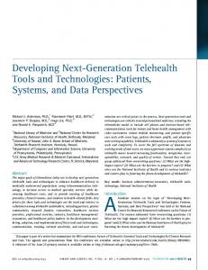
Fig. 2. Network Diagram
1) Network Diagram: Diagrams present the network architecture of a system including device nodes (switches, routers, servers, IEDs, etc.) and network links together with other information such as network addressing. Such diagrams are common today in any computer network domain to convey the physical network structure. 1 Project support under the QREN framework has been approved.
CIRED
20th International Conference on Electricity Distribution
Prague, 8-11 June 2009 Paper 0322
Srv1
Srv1
SS_GW_1
SS_GW_2
MmsApp
MmsApp
4) System Diagrams: Visualizing a specific distributed or local function is the main goal of functional diagrams. To represent the overall functionality of a system (or subsystem) functional diagrams would be cluttered and of limited value. System diagrams include the single line diagram of the substation together with the associations to logical nodes that virtualise, monitor, control or protect a given equipment or system component. Allocation of logical nodes to devices is also represented in such diagrams. Several variants of this diagram type have been used in papers to illustrate case studies or examples and have already been made available in some engineering tools.
MmsApp
Srv1
Srv1
Srv1
L1_BCU
BB_BCU
L3_BCU
GoCb1
GoApp
GoApp
GoCb1
Srv1
L1_PT_A GoApp
GoCb1
Srv1
L1_PT_B
Fig. 3. Data Flow Diagram
2) Data Flow Diagrams: In a distributed SAS the physical architecture of the system is not sufficient to describe the global interactions between IEDs for an automation engineer. The relevant data flows (client/server, GOOSE, SMV or other) comprehend an independent logical structure [4] that must be clearly understood for many engineering purposes and can be represented by another diagram type. Q32XSWI1
Q30XCBR1
Pos
Q30CILO1
Q30a2XSWI1 Pos
Intlck1
EnaOpn
Intlck2
EnaCls
Opn
Pos
Cls
Intlck3 Intlck4 Intlck5
Q31XSWI1
Q30CSWI1
Pos
Pos Q30b2XSWI1
Pos
EnaOpn OpOpn
Distributed automation systems in power applications have much to gain from novel engineering environments. To ensure that such upcoming approaches and technology are successful it is also fundamental to address and eventually adapt or revise engineering practices, which ultimately means not only technology but also people. Evolution in distributed systems engineering and management is nevertheless deemed critical. If engineering efficacy and efficiency is an important concern for utilities today, the advent of distributed energy resources and smart grid technology [11] will further complicate matters. It will not only increase functional requirements and introduce new flexibility and adaptability needs, but also bring distributed systems engineering from the station to the power grid. Tools are hence a fundamental piece of the automation system puzzle itself.
OpCls
EnaCls
Pos
CONCLUSION
REFERENCES Fig. 4. Functional Diagram
3) Functional Diagrams: Data flow diagrams are critical to understand communication interactions between IEDs but not to understand detailed functional relationships. The input/output associations between logical nodes of one or more devices can be represented by a function-block-like diagram type. This diagram considers logical nodes as entities which encapsulate behaviour like IEC 61499 function blocks [9,10]. Q32 L1_BCU VT3a
L1_PT_A CT3aTCTR1 CT3aTCTR2 CT3aTCTR3
CT3a
Q32XSWI1
Q32CILO1
Q32CSWI1
VT3aTVTR1 VT3aTVTR2 VT3aTVTR3
CT3aSVLT1
KLXCALH1
CT3aTCTR1 CT3aTCTR2 CT3aTCTR3
L1MMXU1
NURCALH1
Q32SSWI1
URSPTCALH1 L1PTOC1 L1PTOC2
GND
Q30a
Q30
L1PTTRC
Q30XCBR1
GND
Q30b
Q30aXSWI1
Q30aCILO1
Q30aCSWI1
Q30XCBR1
Q30CILO1
Q30CSWI1
Q30aSSWI1
Q30SCBR1
Q30bXSWI1
Q30bCILO1
Q30bCSWI1
Q30bSSWI1
Q31XSWI1
Q31CILO1
Q31CSWI1
Q31SSWI1
Q31
GND L1
Fig. 5. System Diagram
CIRED2009 Session 3
Paper No 0322
[1] C. Brunner, 2008, "IEC 61850 for Power System Communication", 2008 T&D IEEE/PES [2] G. Senfter, 2007, "IEC61850 – Is it Worth the Trouble?", CIRED 2007 [3] K. Schwarz, 2007, "Impact of IEC 61850 on System Engineering, Tools, Peopleware and the Role of the System Integrator", DistribuTech 2007 [4] L. Hossenlopp, 1999, "Engineering Perspectives on IEC 61850", IEEE power & energy magazine. vol. 3, 45-50 [5] EDP, Relatório e Contas 2007, Rede de Distribuição em Portugal, http://alencastre.ipapercms.dk/EDP/documentos/relatoriosdecontas/ 2007/Pt/Instalacoes/ [6] EDP Distribuição, 2007, Projecto-tipo de subestações AT/MT, http://www.edp.pt/EDPI/Internet/PT/Group/Peers/Professionals/Po werstation/default.htm [7] M. Mendoza, J. Castellanos et. al., 2007, "iSAS. New Iberdrola’s SAS Engineering Process for Integrating Protection, Control, Telecontrol and Monitoring Functions by Means of New Standards”, CIGRÉ B5 Colloquium [8] A. Carrapatoso, R. Cartaxo et. al., 2006, "INTEGRA Project – Applying IEC 61850 Technology", CIGRÉ 2006 [9] R. Paulo, 2008, "Functional Integration in Substation Automation Systems: System Tools and Interoperability", CIGRÉ B5 Colloquium [10] N. Higgins et. al., 2008, "Concept for Intelligent Distributed Power System Automation with IEC 61850 and IEC 61499", IEEE SMC 2008 [11] J. Roncero, 2008, "Integration Is Key to Smart Grid Management", CIRED Seminar 2008: SmartGrids for Distribution