They will be a guide to installing the system in an efficient and professional ....
Linear's Model CCM-1 (P/N ACP00904) CCTV camera can be installed inside
the ...
Aug 29, 2000 ... through first hand experience with a semester long aircraft design, build, and ...
Dr. Jan Roskam, Airplane Design, Volumes I and II, Roskam ...
CSN EN287-1, CSN EN 473, CSN EN ISO 15614-1, CSN EN ISO 15613, CSN
EN ISO. 17662, CSN EN ISO 15609-1, CSN EN ISO 5817. The group of basic ...
Abstract. Let F be a finite real valued function defined on [0, 1]. We prove that F can be transformed into a function which is differentiable a.e. by a homeomorphic ...
span class news dt Nov 09 2016 span nbsp 0183 32 Click Here http succespdf site book ... Read Flight: 100 Greatest Aircr
Apr 9, 2015 - delivered (owned and managed) fleet of 143 aircraft and commitments ... Hosting inaugural capital markets
Apr 9, 2015 - Q1 results will be announced at 6.00am ET (11.00am BST) on May 6, 2015 with a conference call at. 8.30am E
eBooks Flight: 100 Greatest Aircraft Free Download, Free Download Flight: 100 Greatest Aircraft Best Book, PDF Flight: 1
... websites and apps On July 12th a member from a popular boating message ... PDF Flight: 100 Greatest Aircraft Free Do
exchange resin (100g of resin/litre of 8M-urea) immediately before use. ... ated ac-crystallin was dissolved in 2 mM-phosphate buffer,. pH7.6, containing ...
servisním mechanikem JUNKERS uveden do provozu. Po celou dobu ... Přehled
typů. ZS 23-1. AE. 23. ZS 23-1. AE. 31. ZW 23-1. AE. 23. ZW 23-1. AE. 31.
Nov 16, 2017 - 0.9059 × 0.150 = 89.78lb/ft2 = 550.97Kg/m2. (4.16) .... (5.8). The leading edge sweep can be calculated using the Eqs. 5.8, 5.5 and4.14, as.
04/08/2014. 4 TNE04-M ZZ. (CI)/(AE). â. 2002. â. â. 6 9. 7 6. 85. F a n s. -. TPE -L-TN E 0 4M ZZ-0 0 5-0 40 8 1 4
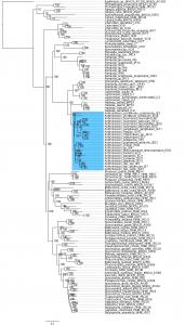
Muhlenbergia tricholepis. Sohn sia filifolia. Bouteloua gracilis. Bouteloua dimorpha. Bouteloua curtipendula. Bouteloua dactyloides. Bouteloua dactyloides.
biuncialis, Aegilops geniculata and Aegilops triuncialis respectively. In the Ae. ..... jointed goatgrass (Aegilops cylindrica Host), as revealed by RAPD and ...
These notes provide an introduction to the engineering science of flight dynamics
, focusing primarily of aspects of stability and control. The notes contain a ...
Oct 24, 2011 ... prides itself not just on bringing its readers up to speed with the ... Mainstream
OEMs such as Nissan are taking a share .... techniques such as circuit diagram-
based design ...... Preflighting documents prior to creating a PDF.
Any model other than the basic models will have a supplemental manual
included ... E] Front panel Input Plug-in Modules allow flexibility and
customization.
Liste de pièces de rechange. Onderdelenlijst. Ersatzteilliste. Lista parti di
ricambio. Spare parts list. Lista de repuestos. ( 01.06 ). JF. ZW / ZS 23 AE… V
033.
energy storage, operational flexibility, steam turbine, gas turbine, SOEC, hydrogen technologies, machine monitoring .... storage volumes because the unit energy stored in hot water is relatively small (for .... Printers, 2004, pp. 213â220. 14.
Tobacco - NIPHMhttps:// › publication › links › AE...https:// › publication › links › AE...CachedPDFBalaji Scan Pvt. Ltd., ... promotes experiential learning and discovery based decision making by ... Andhra Pradesh and West Bengal and chewing tobacc
Jul 8, 2010 - Editor: Nathan D. Price, University of Illinois at Urbana-Champaign, United States of ... the rapid lateral propagation of receptor tyrosine kinase activation ... feedback loop, proteins A and protein B inhibit or repress each ...... Gu
Students learn to fly R/C planes and take data from instrumented ... Students
design a R/C hand launched glider or flying wing ... R/C Flying Wing Design
Project.
Introduction to Aerospace Engineering A Freshman-level Course in Aircraft Performance and Design
AE 100: Introduction to Aerospace Engineering • Objective: Introduce incoming freshman students to aspects of aerospace engineering giving them hands-on problem solving design and data collection experience
• Currently: two sections – Spacecraft and rocket design – Aircraft design
UNIVERSITY OF ILLINOIS AT URBANA-CHAMPAIGN DEPARTMENT OF AEROSPACE ENGINEERING
2
AE 100: Intro to Aerospace Engineering - History of Aircraft Design - Case Study of Vehicle Development - Aircraft/Flight Theory and Design - Engineering Ethics - Hands-on Experiences (2 of 3) • Discovery Flights • Students fly in an aircraft • Radio Control Flying and Aircraft Performance • Students learn to fly R/C planes and take data from instrumented aircraft • R/C Aircraft Design Project • Students design a R/C hand launched glider or flying wing UNIVERSITY OF ILLINOIS AT URBANA-CHAMPAIGN DEPARTMENT OF AEROSPACE ENGINEERING
3
R/C Flying and Aircraft Performance • Student R/C Flying Experience (CCRCC-AMA) Description: Students have the opportunity to pilot a 4-channel R/C trainer with hobbyists from the local R/C flying club. Students learn about basic flight maneuvers and aircraft control.
• Instrumented R/C Aircraft Performance Description: Students collected data from instrumented R/C aircraft with on-board imaging data recording and telemetry for class examples and homework problems. UNIVERSITY OF ILLINOIS AT URBANA-CHAMPAIGN DEPARTMENT OF AEROSPACE ENGINEERING
4
Instrumented R/C Aircraft Flight Testing Eagle Tree Systems
• GPS
• Engine Temperature
• Altimeter
• Current / Voltage
Data Recorder
X/Y Accelerometer
• Pitot/Static Pressure • Telemetry • x / y Accelerometer
• Servo Positions
• Optical RPM
• Angle of Attack
GPS Telemetry
Angle of Attack
Pitot/Static Probe
UNIVERSITY OF ILLINOIS AT URBANA-CHAMPAIGN DEPARTMENT OF AEROSPACE ENGINEERING
5
Instrumented R/C Aircraft Flight Testing Flaps and lift
Airspeed, altitude, and acceleration
GPS
X/Y Accelerometer Pitot/Static Probe
UNIVERSITY OF ILLINOIS AT URBANA-CHAMPAIGN DEPARTMENT OF AEROSPACE ENGINEERING
6
Instrumented R/C Aircraft Flight Testing Stall and Flow Separation
Tufts
Video Camera
UNIVERSITY OF ILLINOIS AT URBANA-CHAMPAIGN DEPARTMENT OF AEROSPACE ENGINEERING
7
Instrumented R/C Aircraft Flight Testing Flow Separation and Effectiveness of Wingtip Side-Force Generators (SFGs) During Knife-Edge Maneuvers
SFGs Tufts
UNIVERSITY OF ILLINOIS AT URBANA-CHAMPAIGN DEPARTMENT OF AEROSPACE ENGINEERING
8
Instrumented R/C Aircraft Flight Testing Flow Separation and Effectiveness of Wingtip Side-Force Generators (SFGs) During Knife-Edge Maneuvers Ground and in-flight video of R/C aircraft with SFG First with tufts on low-pressure side and then with tufts on high-pressure side of SFGs
UNIVERSITY OF ILLINOIS AT URBANA-CHAMPAIGN DEPARTMENT OF AEROSPACE ENGINEERING
9
Instrumented R/C Aircraft Flight Testing Flow Separation and Effectiveness of Wingtip Side-Force Generators (SFGs) During Knife-Edge Maneuvers
Viewing low pressure side of SFG • Tufts on wing indicate no separation • Tufts indicate flow separation on SFG
Viewing high pressure side of SFG • Tufts on wing indicate no separation • Tufts indicate no separation on SFG
Flight Data of Aircraft in Knife-Edge with and without SFGs No SFGs With SFGs
Airspeed [mph] 59.8 59.6
Rudder Deflection [Degrees] 25.7 12.6
Motor Speed [RPM] 8841 8789
* For approximately the same aircraft speed the rudder deflection angle (indicating to a first order the yaw angle) is less when using SFGs UNIVERSITY OF ILLINOIS AT URBANA-CHAMPAIGN DEPARTMENT OF AEROSPACE ENGINEERING
10
R/C Design Project Description: Students are given a foam wing, battery pack, and flexible servo package which they utilize to design and evaluate the performance of a hand-launched glider or powered flying wing.
UNIVERSITY OF ILLINOIS AT URBANA-CHAMPAIGN DEPARTMENT OF AEROSPACE ENGINEERING
11
R/C Flying Wing Design Project Initial Measurements and Calculations (weight) – Wing, Battery, and Servo Package E-flite 300 motor, Propeller, and mount:
Flat swept wing Relatively Low AR Carbon fiber leading edge
Spectrum AR6110e Receiver (Rx)
Servos Spectrum S75 (2)
UNIVERSITY OF ILLINOIS AT URBANA-CHAMPAIGN DEPARTMENT OF AEROSPACE ENGINEERING
E-flite 10amp Electronic Speed Controller
12
R/C Flying Wing Design Project Conceptual Designs and Evaluation Motor/Propeller Configuration Front Prop
Pusher Prop
Vertical Stabilizer Configuration and Location
Elevon Shape
Rectangle Arc /ellipse Trapezoid Other
UNIVERSITY OF ILLINOIS AT URBANA-CHAMPAIGN DEPARTMENT OF AEROSPACE ENGINEERING
R/C Flying Wing Design Project Design Calculations – Tail length – Tail and control surface sizing (TVR) – Moment, force, and stability calculations Lrx
Lecs Wrx
Wecs
Wv Wb We
Wsrv
Ww
Aerodynamic Center of the Wing
Wm
Wps Wbp
Lm Lv
Le
Lb
Lsrv
Lw Lps
0
Lbp
– Component dimensions and lay-out UNIVERSITY OF ILLINOIS AT URBANA-CHAMPAIGN DEPARTMENT OF AEROSPACE ENGINEERING
14
R/C Flying Wing Design Project
UNIVERSITY OF ILLINOIS AT URBANA-CHAMPAIGN DEPARTMENT OF AEROSPACE ENGINEERING
15
Thank you
UNIVERSITY OF ILLINOIS AT URBANA-CHAMPAIGN DEPARTMENT OF AEROSPACE ENGINEERING


![[PDF] Flight: 100 Greatest Aircraft Full Colection - Google Sites](https://m.moam.info/img/260x300/pdf-flight-100-greatest-aircraft-full-colection-go_64783f69097c47a9708c9d43.jpg)


![[PDF] Flight: 100 Greatest Aircraft Online Books - Google Sites](https://m.moam.info/img/260x300/pdf-flight-100-greatest-aircraft-online-books-goog_6478ab92097c474c228d63e4.jpg)
![[PDF] Download Flight: 100 Greatest Aircraft Online ePub - Google Sites](https://m.moam.info/img/260x300/pdf-download-flight-100-greatest-aircraft-online-e_64782867097c474e708c8051.jpg)