Experimental Investigations of Stability in a Hybrid Stepper Motor Radosław KĊpiĔski1, Jan Awrejcewicz2, Donat Lewandowski2, and Jakub Gajek1 1
Faculty of Mechanical Engineering, Lodz University of Technology, Poland 2 Department of Automation, Biomechanics and Mechatronics, Faculty of Mechanical Engineering, Lodz University of Technology, Poland
[email protected]
Abstract. In our investigations we analyze the dynamics of a two-phase hybrid stepper motor. Its behavior is governed by a system of four non-linear ordinary differential equations. We focus on the instability phenomena occurring during the operation of the device at different frequency intervals. Such instabilities can lead to a loss of synchronism and consequently to motor’s failure. The dynamics of a realistic system driven by a stepper motor is analyzed experimentally using a phase current sensing method in order to understand the dynamical processes governing the instability phenomena. The applied measuring system allowed to acquire a number of phase plots showing the behavior of the system at different angular velocities. Results indicate that qualitative change is phase plots is correlated with the loss of motor stability. Keywords: stepper motor, stability, step-out.
1
Introduction
1.1
Scope of the Research
This paper deals with the analysis of dynamics of a system consisting of a hybrid stepper motor loaded with a rotating cylindrical mass. Such synchronous electrical motors are commonly used in a number of industrial and household mechatronic devices such as positioning systems, scanners, printers, digital cameras, optical drives, etc. This type of motor possesses an important advantage over other types of drives: they can be used to design very compact and simple positioning systems using the open-loop approach, i.e. position feedback is not necessary. However, this comes with a drawback of having to incorporate an appropriate control system, that is relatively more sophisticated than, for instance, in the case of DC motors. Additionally, a number of methods increasing the system performance are widely used, such as voltage chopping and micro-stepping. Several authors gathered the “know-how” regarding stepper motors, including the operation principles, design problems, control methods and mathematical modelling. In particular works by Kenjo [1] and Aclarney [2] should be mentioned. The former © Springer International Publishing Switzerland 2015 J. Awrejcewicz et al. (eds.), Mechatronics: Ideas for Industrial Applications, Advances in Intelligent Systems and Computing 317, DOI: 10.1007/978-3-319-10990-9_8
[email protected]
81
82
R. KĊpiĔski et al.
shared his knowledge gained during his long-term collaboration with Sanyo Electric Co. Ltd. who were one of the precursors of the stepper motor technology. The latter wrote a practical guide to the application of the stepper motors in engineering. It can be observed that for high speeds this type of motor can behave unpredictably – for example rotor stalling can occur which can lead to a failure of the whole positioning system. It appears however, that those instabilities are occurring only in certain excitation frequency intervals. Those instability phenomena attracted the attention of several researchers, such as Balakrishnan et al. [3] and Cao et al. [4]. The former carried out an experimental investigation, similar to the one described in this work and the latter analyzed the dynamic of the system of ODEs concerning stepper motors. In our research we are aimed at experimentally analyzing dynamics of a system actuated by a bipolar hybrid stepper motor on a basis of phase current measurement. A mathematical model regarding such system has been also proposed. This allows us to use a numerical simulation to confirm the phenomena observed in the experiment in the future research. 1.2
Physical System
The object of the investigations is an electro-mechanical system consisting of the following elements: • • • • •
hybrid, two phase, bipolar stepper motor, stepper motor controller, programmable logic controller (PLC), 36 VDC power supply unit, incremental rotary encoder.
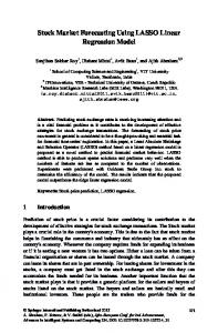
The overview of the system is presented in Fig. 1. It can be seen that the velocity and position control is done by the PLC through a pulse signal passed to the motor’s controller. This device is responsible for applying appropriate voltages to the motor’s windings using the electrical power from the dedicated power supply. The power supply operates at 36 V DC and is not stabilized, because the controller uses a voltage chopper.
Fig. 1. Diagram showing the considered electro-mechanical system
[email protected]
Experimental Investigations of Stability in a Hybrid Stepper Motor
83
As can be clearly seen in Table 1, the nominal voltage of the hybrid stepper motor is only 5 V. Voltage chopper circuit, however, allows to increase the performance of the motor, because larger supply voltage means that the first time derivatives of the phase currents are of a higher value (as shown in Section 2). Consequently, the windings can be energized much more rapidly, producing (on average) more torque. Additionally, micro-stepping approach is used, which reduces the noise and vibration of the system, in addition to increasing the resolution of the positioning system. In this system a position feedback using a rotary encoder has been introduced to allow for measuring the system response. Although we did not track accurately the position response of the system in the described experiment, this feedback signal allowed to detect the moments when a loss of synchronism occurs. Mechanical part of device can be seen in the photo presented in Fig. 2. It consists of a shaft and cylindrical mass supported on a ball bearing coupled with the motor using Oldham’s coupler.
Fig. 2. Electro-mechanical system actuated by a stepper motor: stepper motor (1), Oldham’s coupler (2), ball bearing support (3), rotating mass (4)
2
Mathematical Model
A hybrid stepper motor consists of a rotor made of alternately placed permanent magnet poles with equally spaced grooves placed around its circumference and a stator consisting of windings. In the case of a two phase motor we have two windings:
[email protected]
84
R. KĊpiĔski et al.
A and B, which have equal inductance L and resistance R. Fig. 3 shows a simplified model of a two phase bipolar hybrid stepper motor, which is the basis for further investigations.
Fig. 3. Physical model of the hybrid stepper motor
The differential equations governing the dynamics of a hybrid stepper motor system have been already presented in numerous works including [1–2, 5–7]. Owing to the two main laws affecting the system (Kirchhoff’s 2nd Law and Newton’s 2nd Law of Motion) we can establish the following system of non-linear differential equations:
dI A + RI A = V A + K mω sin (N γ ϕ ) dt dI L B + RI B = VB + K mω cos(N γ ϕ ) dt dω J + cω + Tl = − K m I A sin (N γ ϕ ) + K m I B cos(N γ ϕ ) dt dϕ =ω dt L
(1)
where: IA, IB are currents in both phases; VA and VB are voltages applied to the windings; R, L are winding's resistance and inductance, respectively; Km is the motor torque constant, c is viscous friction coefficient, Nr is the number of rotor teeth, J is rotor's moment of inertia, Tl is the load torque, Ȧ is the rotor speed and ij is its angular position.
[email protected]
Experimental Investigations of Stability in a Hybrid Stepper Motor
85
Table 1. Parameters of the system
R L IA0 = IB0 VA0 = VB0 c Km J Nr
3
5ȍ 8.6 · 10-3 H 1A 5V 8 · 10-4 N· m·s / rad 0.55 · N·m / A 11 · 10-6 kg· m2 50
Experimental Set-Up
The phase currents, especially for high rotor velocities are changing with high speed. Because of that, a measuring system is required that can gather a sufficient number of samples per second. In this case, a digital oscilloscope has been used, which offers sampling rates of 1 Gs/s. To measure high frequency currents an amplifying circuit is also necessary. We use a shunt resistor current sensing method, introducing two very small value resistor in series with the phase circuits. Voltage drop occurring on these resistors, owing to Ohm’s Law is proportional to the current flowing through the phase. This voltage signal is then amplified using two (one for each phase) bi-directional shunt current sensors with the amplification ratio of 50. The resulting signal is passed to the two channels of the oscilloscope, allowing to draw XY plots of both phase currents, in such a way that IA value determines the X coordinate and IB determines the Y coordinate. The circuit has been designed using a PCB board, with two connectors allowing to connect the device between the motor and its controller. A photo of the board can be seen in Fig. 4.
Fig. 4. Two phase bi-directional shunt current sensor
4
Methodology and Results
Following methodology has been applied for the experiment: 1. the amplifying circuit has been connected between the motor and the controller, 2. the controller has been set to 1:16 micro-stepping,
[email protected]
86
R. KĊpiĔski et al.
3. digital oscilloscope has been connected to the amplifier (one channel for each phase), 4. system has been excited with gradually increasing frequency (from 30 Hz up to 20 kHz), 5. for each of the frequencies an image of the XY plot has been saved, 6. frequencies at which loss of synchronism occurred have been marked as “unstable”. The results of those steps have been gathered and shown in Table 2. Table 2. Phase current plots obtained during the experiment
30 Hz
500 Hz
2.5 kHz
3.5 kHz
[email protected]
Experimental Investigations of Stability in a Hybrid Stepper Motor Table 2. (continued)
5.5 kHz
6.5 kHz
7.5 kHz
9 kHz
11 kHz (unstable)
11.15 kHz (unstable)
[email protected]
87
88
R. KĊpiĔski et al. Table 2. (continued)
11.5 kHz
12.5 kHz
13.6 kHz
14.5 (unstable)
16 kHz
17 kHz
[email protected]
Experimental Investigations of Stability in a Hybrid Stepper Motor
89
Table 2. (continued)
18 kHz
19.9 kHz
Plots shown in the above table allow to observe change of the trajectory on IA – IB plane, associated with the increase of the excitation frequency. For the low frequencies (below 2.5 kHz) separate points are clearly visible, because the motion of the rotor is not smooth, as it becomes stationary between each step. In this frequency region the captured curve takes a circular shape. However, increasing the stepping speed yields gradual change of shape of the curve. At 5.5 kHz point the trajectory resembles a slightly distorted square. For excitation frequencies above 6 kHz the inner area limited by the trajectory curve starts to shrink. It means that the voltages on the windings are changing too fast to fully energize motor’s coils. For the frequency interval starting at 6 kHz to around 11 kHz we observe further decrease of the inner area, as well as a progressive distortion of shape of the curve. Reaching 11 kHz results in a sudden change of the trajectory shape. This is shortly followed by a rotor stalling. We can observe that the trajectory curve starts to intersect itself in several points. The instability phenomena takes place in the region of excitation frequencies from 11 kHz up to 11.5 kHz. For 11.5 kHz up to 13.8 kHz the system behaves in a stable manner. Between 13.8 kHz and 16.5 kHz, however we deal with another wide instability section, and sudden change of shape occurs once again. Above this region, for the frequencies up to 19 kHz we observe stable operation of the motor. The inner area limited by the trajectory shrinks even further, as we increase the stepping speed. At this point the motor pull-out torque is significantly reduced, and even a small peak of the load torque can lead to the loss of synchronism. For the frequencies reaching 20 kHz the system generally behaved in an unstable manner. Frequencies past the 20 kHz point were not tested. The experiment yields results similar to [3], but they are quantitatively inconsistent owing to the difference in stepper motor type and size. We can make an observation that when the plotted trajectory on the IA – IB plane starts to intersect with itself we probably deal with the instability region.
[email protected]
90
5
R. KĊpiĔski et al.
Concluding Remarks
The proposed measurement system allowed capturing the phase current plots of the investigated system with a sufficient speed and accuracy. Experimental results shown in the previous section allow us to conclude that in the case of the tested hybrid stepper motor we deal with several instability regions associated with different frequency intervals. The first and second observed instability region clearly exhibited a sudden qualitative change in the phase trajectory, when the plotted curve started to intersect with itself in several points. As was expected the area limited by the trajectory decreases with the increase of the excitation frequency, after we move past the point where the windings can no longer be fully energized. At high speeds we deal with several smaller instability regions, but the exact shape of the trajectory becomes increasingly hard to capture, because of the limited accuracy. In further research we are planning to introduce a numerical simulation based on the system of ODEs discussed in Section 2, and to compare it to the experimental results. Additional tests, using other control methods (for instance different step divisions) will also be made.
References 1. Kenjo, T., Sugawara, A.: Stepping motors and their microprocessor control. Oxford University Press Inc., New York (1995) 2. Acarnley, P.: Stepping motors: a guide to theory and practice. The Institution of Electrical Engineers, London (2002) 3. Balakrishnan, K., Umamaheswari, B., Latha, K.: Identification of resonance in hybrid stepper motor through measured current dynamics in online for accurate position estimation and control. IEEE Trans. Ind. Inf. 9, 1056–1063 (2013) 4. Cao, L., Schwartz, H.M.: Oscillation, Instability and Control of Stepper Motors. Nonlinear Dynamics 18, 383–404 (1999) 5. Bodson, M., Chiasson, J., Novotnak, R., Rekowski, R.: High performance nonlinear feedback control of a permanent magnet stepper motor. In: Proceedings of 1st IEEE Conference on Control Systems Technology, vol. 1, pp. 510–515 (1992), doi:10.1109/CCA.1992.269821 6. Kuo, B., Tal, J.: Incremental motion control: step motors and control systems. SRL Publishing Company, Champaign (1979) 7. Lyshevski, S.E.: Electromechanical systems, electric machines and applied mechatronics. CRC Press, Boca Raton (2000)
[email protected]