dependent on engine speed than the DC only system. • Two wires of the same
color ... Introduction. © Briggs & Stratton Alternator Specifications MS2288bk 6/11
...
Alternator Specifications
Meters
Diagnostic Tool 19468 DC Shunt The DC shunt is a very useful tool, especially when working with higher amperages. To use, the electrical system must be opened and the shunt installed on the negative terminal of the battery. In this position, all energy going into and coming out of the battery must pass through the shunt. The shunt is designed to read voltage drops due to the resistance of the metal between the two meter lead connections. The resistance value has been carefully set to allow the meter to use the millivolt scale. In use, 1 millivolt equals 1 amp. Dealing with millivolts is much safer than dealing with amps.
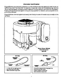
Introduction To identify an alternator system, inspect wire or wires that come from under or behind the blower housing. • A single wire with no diode is generally, but not always, an AC only system • A single wire with a diode is generally a DC only system. The diode rectifies AC to DC for battery charging. This system is unregulated in that the energy delivered to the battery is totally dependent on engine speed • A red wire with a diode and black wire without a diode is a Dual Circuit system that offers DC for battery charging and AC to power lights • A single wire feeding an electronic component (regulator/ rectifier) is a rectified and regulated system which is less dependent on engine speed than the DC only system • Two wires of the same color feeding a regulator/rectifier is a rectified and regulated system that offers even more energy Most Digital Multi Meters (DMM) are able to read up to 10 amps for short periods of time. At or above 10 amps, consider using a DC shunt or a clamp on type meter to prevent meter damage. When measuring energy being returned to the battery, Briggs & Stratton specifications are provided in DC amps. The power is initially provided from the stator as AC and must go through a rectification process. If the battery will not charge, the fault may be the battery, rectifier (diode), regulator/rectifier or stator. A troubleshooting flow chart will usually start at the battery and work backwards. As there is no bench test for regulator/rectifiers, test AC output from the stator. If the battery and AC output are OK, replace the regulator/rectifier by process of elimination. AC tests are made for AC volts while tests for DC charging output are made in DC amps. One or both will be used to check the health of all Briggs & Stratton alternator systems.
© Briggs & Stratton Alternator Specifications MS2288bk 6/11
Introduction How to Use These cards supply information on the different alternator systems provided by Briggs & Stratton. Identify the system being tested by the wire or wires that extend from behind the flywheel. Record the number and color of the wires and the color and general type of connector the wires terminate in. At the top of each card is the system name displayed on that card followed by a picture of the wire(s), color and connector. If a regulator/rectifier is part of the system, a picture will be displayed of it. From this information, determine which system is installed on the engine to be tested. Once the system is identified, turn the card over. The first graphic is how the system would be installed in the simplest manner. The next graphic is how to hook up the test meter. Test specifications to expect follow at the bottom of the page.
Testing Unregulated charging systems always deliver the same amount of energy to the battery (based on rpm) whether it requires charge or not. Regulated charging systems are designed to provide charge to the battery based on its need. The output from the unregulated system is predictable as long as the rpm is held steady. Regulated system output will vary based on the battery state of charge. After activating the starter motor to start the engine, charge rate will typically be high as the alternator replaces the energy used by the starter. The charge rate will reduce slowly as the battery state of charge levels off. This means that test specifications can be a moving target. The test specifications for regulated systems are generally stated as a range such as 1 to 10 amps DC or 3 to 16 amps DC. © Briggs & Stratton Alternator Specifications MS2288bk 6/11
DC Only
Part
Part Number
Stator
794103
© Briggs & Stratton Alternator Specifications MS2288bk 6/11
1
DC Only
Test Specifications @ 2800 rpm AC volts
NA
DC amps
.5 adc minimum
DC amps
.4 adc minimum
(DOV® engines with an aluminum flywheel)
1
© Briggs & Stratton Alternator Specifications MS2288bk 6/11
DC Only
Part
Part Number
Stator
397880
© Briggs & Stratton Alternator Specifications MS2288bk 6/11
2
DC Only
Test Specifications @ 2800 rpm
2
AC volts
NA
DC amps
.5 adc
© Briggs & Stratton Alternator Specifications MS2288bk 6/11
DC Only
Part
Part Number
Stator
793640
Diode
391507
© Briggs & Stratton Alternator Specifications MS2288bk 6/11
3
DC Only
Test Specifications @ 3600 rpm
3
AC volts
NA
DC amps
1.5 adc
© Briggs & Stratton Alternator Specifications MS2288bk 6/11
DC Only
Part
Part Number
Stator
695730
Diode
391507
© Briggs & Stratton Alternator Specifications MS2288bk 6/11
4
DC Only
Test Specifications @ 3600 rpm
4
AC volts
NA
DC amps
3.0 adc
© Briggs & Stratton Alternator Specifications MS2288bk 6/11
DC Only
Part
Part Number
Stator
694457
Diode
391507
© Briggs & Stratton Alternator Specifications MS2288bk 6/11
5
DC Only
Test Specifications @ 3600 rpm
5
AC volts
NA
DC amps
1.5 adc
© Briggs & Stratton Alternator Specifications MS2288bk 6/11
DC Only
Part
Part Number
Stator
696578
Diode
391507
© Briggs & Stratton Alternator Specifications MS2288bk 6/11
6
DC Only
Test Specifications @ 3600 rpm
6
AC volts
NA
DC amps
3.0 adc
© Briggs & Stratton Alternator Specifications MS2288bk 6/11
DC Only
Part
Part Number
Stator
393809
Diode
391507
Harness
393422
© Briggs & Stratton Alternator Specifications MS2288bk 6/11
7
DC Only
Test Specifications @ 3600 rpm
7
AC volts
NA
DC amps
3.0 adc
© Briggs & Stratton Alternator Specifications MS2288bk 6/11
AC Only
Part
Part Number
Stator
391595
© Briggs & Stratton Alternator Specifications MS2288bk 6/11
8
AC Only
Test Specifications @ 3600 rpm
8
AC volts
14 vac
DC amps
NA
© Briggs & Stratton Alternator Specifications MS2288bk 6/11
Dual Circuit
Rectified or Regulated
Part
Part Number
Stator
698230
Diode
319507
Regulator/Rectifier
790292
© Briggs & Stratton Alternator Specifications MS2288bk 6/11
9
Dual Circuit
Rectified or Regulated
Test Specifications @ 3600 rpm
9
AC volts
14 vac
DC amps
3 adc
DC amps through regulator
5 adc
© Briggs & Stratton Alternator Specifications MS2288bk 6/11
Dual Circuit
Rectified or Regulated
Part
Part Number
Stator
696742
Diode
319507
Regulator/Rectifier
790292
© Briggs & Stratton Alternator Specifications MS2288bk 6/11
10
Dual Circuit
Rectified or Regulated
Test Specifications @ 3600 rpm
10
AC volts
14 vac
DC amps
3 adc
DC amps through regulator
5 adc
© Briggs & Stratton Alternator Specifications MS2288bk 6/11
Dual Circuit
Rectified or Regulated
Part
Part Number
Stator
696459
Diode
319507
Regulator/Rectifier
790292
© Briggs & Stratton Alternator Specifications MS2288bk 6/11
11
Dual Circuit
Rectified or Regulated
Test Specifications @ 3600 rpm
11
AC volts
14 vac
DC amps
3 adc
DC amps through regulator
5 adc
© Briggs & Stratton Alternator Specifications MS2288bk 6/11
Dual Circuit
Rectified or Regulated
Part
Part Number
Stator
793118
Diode
391507
Regulator/Rectifier
790292
© Briggs & Stratton Alternator Specifications MS2288bk 6/11
12
Dual Circuit
Rectified or Regulated
Test Specifications @ 3600 rpm
12
AC volts
14 vac
DC amps
3 adc
DC amps through regulator
5 adc
© Briggs & Stratton Alternator Specifications MS2288bk 6/11
4 Amp Regulated - MHI
Part
Part Number
Stator
715255
Regulator
715200
© Briggs & Stratton Alternator Specifications MS2288bk 6/11
13
4 Amp Regulated - MHI
There should be continuity across two leads from stator and no continuity between either lead and ground.
Test Specifications @ 3600 rpm
13
AC volts
NA
DC amps
1g4 adc
© Briggs & Stratton Alternator Specifications MS2288bk 6/11
9 Amp without battery
Part
Part Number
Stator
698314
Regulator
698315
© Briggs & Stratton Alternator Specifications MS2288bk 6/11
14
9 Amp without battery
Test Specifications @ 3600 rpm
14
AC volts
40 vac
DC amps
1g9 adc
© Briggs & Stratton Alternator Specifications MS2288bk 6/11
5 or 9 Amp Regulated
Part
Part Number
Stator
698314
Regulator
794360
© Briggs & Stratton Alternator Specifications MS2288bk 6/11
15
5 or 9 Amp Regulated
Test Specifications @ 3600 rpm AC volts 5 amps system
28 vac
9 amps system
40 vac
DC amps
15
5 amps system
5 adc
9 amps system
9 adc
© Briggs & Stratton Alternator Specifications MS2288bk 6/11
Tri-Circuit
Part
Part Number
Stator
696457
Harness
691955
Diode
391507
DC Shunt
19468
© Briggs & Stratton Alternator Specifications MS2288bk 6/11
16
Tri-Circuit
5 amps +DC
5 amps -DC
Test Specifications @ 3600 rpm
16
AC volts
28 minimum
DC amps at shunt
5 minimum
© Briggs & Stratton Alternator Specifications MS2288bk 6/11
5 or 9 Amp Regulated
Part
Part Number
Stator
696457
Regulator/Rectifier
794360
Note: The difference between the 5 and 9 amp regulated systems is the size of the magnets on the flywheel. Small on the 5 and large on the 9.
© Briggs & Stratton Alternator Specifications MS2288bk 6/11
17
5 or 9 Amp Regulated
Test Specifications @ 3600 rpm AC volts 5 amps system
28 vac
9 amps system
40 vac
DC amps at shunt
17
5 amps system
5 adc
9 amps system
9 adc
© Briggs & Stratton Alternator Specifications MS2288bk 6/11
5 Amp Regulated without battery
Part
Part Number
Stator
696457
Regulator/Rectifier
698315
© Briggs & Stratton Alternator Specifications MS2288bk 6/11
18
5 Amp Regulated without battery
Test Specifications @ 3600 rpm
18
AC volts
28 vac
DC amps
5 adc
© Briggs & Stratton Alternator Specifications MS2288bk 6/11
10 Amp
Regulated
Part
Part Number
Stator
695466
Regulator/Rectifier
691185
© Briggs & Stratton Alternator Specifications MS2288bk 6/11
19
10 Amp
Regulated
Test Specifications @ 3600 rpm
19
AC volts
20 vac
DC amps
1g10 adc
© Briggs & Stratton Alternator Specifications MS2288bk 6/11
10 Amp
Regulated - MHI
Part
Part Number
Stator
715194
Regulator
691185
Connector, yellow
399916
© Briggs & Stratton Alternator Specifications MS2288bk 6/11
20
10 Amp
Regulated
There should be continuity across two leads from stator and no continuity between either lead and ground.
Test Specifications @ 3600 rpm
20
AC volts
NA
DC amps at shunt
1g10 adc
© Briggs & Stratton Alternator Specifications MS2288bk 6/11
10 Amp
Regulated
Part
Part Number
Stator
715798
Regulator
691185
Connector
399916
© Briggs & Stratton Alternator Specifications MS2288bk 6/11
21
10 Amp
Regulated
Test Specifications @ 3600 rpm
21
AC volts
20 vac
DC amps at shunt
1g10 adc
© Briggs & Stratton Alternator Specifications MS2288bk 6/11
10, 13 or 16 Amp Regulated
Part
Part Number
Stator
696458
Regulator*
808877
Regulator**
691185
Regulator***
493219
*Brown and orange wire go to charge indicator device. **10, 13 or 16 amps based on flywheel magnet size ***Blue wire is for a charge indicator light
© Briggs & Stratton Alternator Specifications MS2288bk 6/11
22
10, 13 or 16 Amp Regulated
Rd=Charge lead Brn=Charge indicator light AC
Rd Brn Or
AC 808877
NOTE: Connect red to orange to turn the system on and to test output.
Blue=Charge indicator light Charge lead
AC
Blue
AC
Rd AC
Rd
493219
DC
AC 691185
Test Specifications @ 3600 rpm 10 Amp AC volts DC amps at shunt 13 Amp AC volts DC amps at shunt 16 Amp AC volts DC amps at shunt
22
20 vac 1g10 adc 20 vac 1g13 adc 30 vac 1g16 adc
© Briggs & Stratton Alternator Specifications MS2288bk 6/11
20 Amp
Regulated
Part
Part Number
Stator
696579
Regulator
691573
Charge wire
691362
© Briggs & Stratton Alternator Specifications MS2288bk 6/11
23
20 Amp
Regulated
Test Specifications @ 3600 rpm
23
AC volts
29 vac
DC amps at shunt
1g20 adc
© Briggs & Stratton Alternator Specifications MS2288bk 6/11
20 Amp
Regulated
Part
Part Number
Stator
790320
Regulator
790325
© Briggs & Stratton Alternator Specifications MS2288bk 6/11
24
20 Amp
Regulated
Test Specifications @ 3600 rpm
24
AC volts
30 vac
DC amps at shunt
1g20 adc
© Briggs & Stratton Alternator Specifications MS2288bk 6/11
20 Amp
Regulated
Part
Part Number
Stator
795498
Regulator
790325
Regulator
793660
© Briggs & Stratton Alternator Specifications MS2288bk 6/11
25
20 Amp
Regulated
Test Specifications @ 3600 rpm
25
AC volts
30 vac
DC amps at shunt
1g20 adc
© Briggs & Stratton Alternator Specifications MS2288bk 6/11
20-50 Amp Regulated
Part
Part Number
Stator
841178
Regulator
841170
© Briggs & Stratton Alternator Specifications MS2288bk 6/11
26
20-50 Amp Regulated
Test Specifications @ 3600 rpm
26
AC volts
45-50 vac
AC volts
45-50 vac
DC amps at shunt
3g50 adc
© Briggs & Stratton Alternator Specifications MS2288bk 6/11
Literature MS-0415 Engine Alternator Repower Guide Many of you have used this alternator replacement guide to help repower equipment that use alternator systems different from the original specification. We have recently begun to upgrade this guide to better reflect the many questions that we receive from the field. Please note that this guide can be downloaded from The Power Portal website and printed for FREE. If you would like a hard copy please order MS-0415 from your source of supply.
Kit 19615 REPOWER TERMINAL KIT This Engine Repower Terminal Kit will equip you to handle almost any electrical connector or terminal service work on nearly any engine. The generous selection of connectors and terminals provides you with the necessary components to help perform equipment repower. This Engine Repower Terminal Kit is designed to be used in the shop or out in the field. Assembled in a durable case with an easy to follow chart showing the parts, part numbers, quantities and bin locations, the kit offers 5 empty bins so you can add or store any of your important electrical components or tools. All components are replaceable and can be ordered individually. This kit is a great addition to your service repair supplies.
BRIGGS&STRATTON CORPORATION
MS2288bk 6/11
CUSTOMER EDUCATION post office box 702 milwaukee, WI 53201 USA 800 934 7730 |
[email protected] Copyright ©2011. All rights reserved.