584
IEEE TRANSACTIONS ON POWER DELIVERY, VOL. 22, NO. 1, JANUARY 2007
Ampacity of Low-Voltage Power Cables Under Nonsinusoidal Currents Charis Demoulias, Member, IEEE, Dimitris P. Labridis, Senior Member, IEEE, Petros S. Dokopoulos, Member, IEEE, and Kostas Gouramanis, Member, IEEE
Abstract—This paper investigates the ac resistance in the presence of harmonics and proposes ampacity derating factors for cables made according to CENELEC Standard HD603. These cables are widely used in low-voltage industrial and building installations. Four-conductor cables of small, medium, and large conductor cross sections are considered. The fourth conductor is used as the neutral conductor. The cables are modeled using finite-element analysis software. The ac/dc resistance ratio is shown to increase with the frequency of the current and the cross section of the conductor, the increase being much larger when zero-sequence harmonics are present. A derating factor is defined and calculated for five typical nonsinusoidal current loads, for example, computer equipment. The derating of the cable’s ampacity is shown to be very large when zero-sequence harmonics are present. The cross section of the neutral conductor is shown to be significant only when zero-sequence harmonics are present. The validity of the method is verified by comparison with data given in IEEE Standard 519-1992 and with measurements conducted on a cable feeding a large nonlinear load. Index Terms—Cable ampacity, cable resistance, harmonics.
I. INTRODUCTION
T
HE increased use of power-electronics devices in industry and with office equipment has raised an interest in harmonic pollution. Current and voltage harmonics cause a large number of problems for electrical equipment, such as additional losses in conductors, motors, power factor correction capacitors and transformers, malfunction of circuit breakers (CBs) and electronic equipment, and errors in electric power and energy measurement and telephone interference [1], [2]. The additional losses in conductors increase the operating costs in industrial and commercial energy systems [3]. The additional losses caused by harmonic currents must be accounted for by proper derating of the ampacity of the cable. The accurate calculation of a cable’s ampacity, when carrying nonsinusoidal currents, is important for the determination of the rating of its overcurrent protective device. Besides the calculation of a derating factor for the cable ampacity, knowledge of the increased losses, due to harmonic currents, is significant also for the economic evaluation of measures that attenuate harmonic currents. Such measures can be, for example, passive or active harmonic filters [4], [5]. In wye-connected systems, the current in the neutral conductor may be larger than the current in the phase conductors, Manuscript received September 8, 2005; revised April 26, 2006. Paper no. TPWRD-00534-2005. The authors are with the Aristotle University of Thessaloniki, Thessaloniki 54124, Greece (e-mail:
[email protected];
[email protected];
[email protected];
[email protected]). Digital Object Identifier 10.1109/TPWRD.2006.881445
when significant zero-sequence current harmonics are present [6]. This fact may lead to overheating of the neutral conductor unless the neutral is properly sized. The ampacity of low-voltage ( 1-kV) power cables used in Europe is determined in [7] for various installations. However, these ampacities are based on 50-Hz currents. Using analytical equations and assuming balanced three-phase loading of the cables, Rice [8] calculated the increase of cable resistance and, through this, a derating factor for the ampacity of cables with thermoplastic insulation, 90 C rated temperature and nylon jacket (THHN) and of cables with thermoplastic insulation, 75 C rated temperature, moisture resistant and nylon jacket (THWN) as they are specified in Article 310.13 and Table 310.13 of the National Electrical Code (NEC) of the U.S. [17]. These are single-core cables assumed to be immediately adjacent to each other in free air (i.e., no metal conduits were considered). The derating factors calculated for these cable types were later given in IEEE Standard 519-1992 [9]. Later, Meliopoulos and Martin [10] proposed a refinement of the Neher and McGrath [11] analytical equations so that they would reflect the additional cable losses in the presence of harmonics. Their paper addressed the calculation of the effects of harmonics on 600-V cables (as specified by the NEC) laid in metallic or polyvinyl-chloride (PVC) conduits. Their objective was to give simplified formulae for evaluating ohmic losses due to harmonics and, subsequently, to compute a cable derating factor. To derive their formulae, they assumed balanced three-phase loading of the cables. However, they mentioned that when the neutral conductor carries significant zero-sequence harmonic currents, the classic Neher–McGrath equation for ampacity should be used. This equation contains terms such as the ambient earth temperature and the effective thermal resistance between conductors and ambient, which are not readily available. The ampacity derating factor defined in [10] is based on the fundamental current component and not on the root mean square (rms) value of the total current. This issue will be discussed later in this paper. Palmer et al. [12] developed closed-form equations for calculating the ac/dc resistance of high-pressure fluid-filled (HPFF) pipe-type power cables with a metallic shield. Since these cables are used in transmission systems, there is no separate neutral conductor. The metallic shield carries only eddy currents or currents during faults (i.e., it does not serve as a neutral conductor). The results of the proposed closed-form equations were compared with a finite-element analysis model that was developed for the specific cable type. The same equations were used to calculate a derating factor for HPFF cables in five cases of
0885-8977/$20.00 © 2006 IEEE
DEMOULIAS et al.: AMPACITY OF LOW-VOLTAGE POWER CABLES
harmonic loading which are typical for transmission systems [13]. The derating factor defined in [13] is the same with the one defined by Meliopoulos and Martin (i.e., it uses as reference the ampacity at fundamental frequency). A thermal model for calculating cable ampacities in the presence of harmonics is given in [14]. This model includes the effect of currents in the neutral conductor but requires the knowledge of the thermal parameters of the cable, such as thermal resistance, which are not readily available. This paper investigates the effect of harmonics on the losses of PVC-insulated, low-voltage (0.6/1.0-kV) power cables as they are specified by CENELEC Standard HD603 [15]. These cables are widely used for feeding individual loads or distribution switchboards in industrial and commercial power networks. Four-conductor cables (three phases and neutral) are examined. Three phase-conductor cross sections are considered, namely 16 mm , 120 mm and 240 mm , which represent small, medium, and large cables, respectively. Cases where the cross section of the neutral conductor is equal to or less than that of the phase conductors are examined. The cables are modeled using OPERA-2d which is commercially available finite-element analysis software manufactured by Vector Fields Ltd. The cables were assumed to be symmetrically loaded and placed in free air (i.e., no metal conduits or trays were considered). A number of typical power-electronic loads are used to derive ampacity derating factors. The harmonic signature of these loads was measured in industrial environment. Some of the measured loads contain triplen harmonics which cause significant currents to flow in the neutral. Triplen or zero-sequence harmonics are those harmonics that are an integral multiple of three times the fundamental. The current in the neutral conductor and the fact that the triplen harmonics are in phase, are properly modeled to derive the ac resistance of the conductors at various frequencies. This is a main distinction between the present and the aforementioned studies. As will be shown in clause V, the fact that the triplen harmonics are in phase causes a significant increase in the resistance of the conductor. A derating factor, based on the total rms current flowing in the cable, is defined and calculated for a number of cases. The validity of the model developed in this paper is verified by comparison with 1) the ampacity derating given in IEEE Std. 519-1992; 2) the mathematical model developed in [10]; and 3) measurements conducted in a large lighting installation controlled by dimmers. II. CABLE AMPACITIES ACCORDING TO CENELEC STD. HD384 The ampacities of cables in [7] are listed according to their cross section, insulation type, installation type, and the number of active conductors. Ampacity derating factors are given for various ambient temperatures and cable groupings. The ampacity values are valid for 50-Hz currents, and for two or three active conductors. This means that for four-conductor cables, where the fourth conductor is the neutral, only the phase conductors are assumed to be active. It is also assumed in [7] that when the neutral conductor is carrying current to the load, there is a respective reduction in the loading of
585
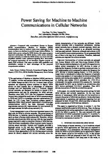
Fig. 1. Cable layouts. L1, L2, and L3: phase conductors. N: neutral conductor. The neutral conductor is shown shaded. Dimensions are shown in Table I. (a) Four-conductor cable with the neutral conductor having the same cross section as the phase conductors. (b) Four-conductor cable with the neutral conductor having a smaller cross section than the phase conductors.
one or more phase conductors so that the total cable losses remain the same. III. CABLE TYPES AND CONFIGURATIONS The cables examined are of the J1VV type as they are specified in [15]. These are PVC-insulated cables, having no metallic sheath and are rated for 0.6/1.0 kV. The configurations examined are shown in Fig. 1 and in Table I. The conductors in all cables were assumed solid. Although this is true only for the 16 mm conductors, this assumption leads to results (cable losses, ac/dc resistance ratio, and ampacity derating) that are on the conservative side. IV. FINITE-ELEMENT ANALYSIS The cables were modeled in two dimensions assuming that at each harmonic frequency, balanced, three-phase, and sinusoidal currents flow through them. The finite-element analysis (FEM) software calculated the spatial distribution of the current density over each conductor’s surface, having as input the average current density. The model of the diffusion equation used by the FEM software is [16] (1)
586
IEEE TRANSACTIONS ON POWER DELIVERY, VOL. 22, NO. 1, JANUARY 2007
monic, the three-phase conductors are assumed to carry the following currents:
TABLE I DIMENSIONS OF THE EXAMINED CABLES
(5a) (5b) (5c) where is the time, is the peak value of the current, and , , and are the three phases. The neutral conductor only carries the eddy currents calculated by the software. For a triplen harmonic, for example, the 3rd harmonic, the phase conductors are assumed to carry the following currents: (6a) (6b) (6c) and the current in the neutral conductor is assumed to be
where is the magnetic vector potential (MVP), is the applied current density, is the conductor permeability, and is the conductivity of the conductor. In two dimensions, only the component of and exist. Therefore, (1) is simplified to
At each harmonic frequency Hz, the software calculates the losses per-unit length in each conductor using the integral
(2)
(8)
Since the MVP and the currents were assumed to vary sinusoidally, they were expressed as the real parts of complex and respectively. Equation (2) now befunctions comes (3) and is solved using complex arithmetic. When the total measurable conductor rms current is given, the software also solves the following equation: (4) where is the surface of the conductor, is the electric scalar potential, and is the total measurable conductor rms current. V. COMPUTATION OF THE
RATIO
To calculate the resistance ratio, an ac steady-state harmonic analysis was employed. Only the odd harmonics, up to the 49th, were considered. The currents in each harmonic frequency were assumed to be of equal magnitude in each phase conductor. However, the phase displacement of the conductor for nontriplen harmonic currents was assumed to be frequencies and zero rads for triplen harmonic frequencies. Hence, the neutral conductor carries only induced eddy currents when nontriplen harmonics are considered. When triplen harmonics are considered, the neutral conductor is assumed to carry the algebraic sum of the phase currents. The following example will clarify the above mentioned points: for a nontriplen harmonic, for example, the 5th har-
(7)
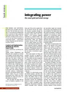
where is the surface of the conductor, is the current density, and is the conductivity of the conductor. Due to the geometry of the cables, the losses in the phase conductors are not identical. In fact, the losses in phase conductors and (Fig. 1) are the same, but, those in are different. The losses per-unit length in the three-phase conductors, when a and of frequency symmetrical current of rms value Hz flows through them, can be defined as , , . The losses in each phase conductor when carand rying a dc current of amplitude can be defined as . The for each phase conductor ( , , ) is shown ratio in Figs. 2 and 3 for cables with relatively small and large cross sections, respectively. Similar results are also obtained for other cross sections. It is easily noticed from Figs. 2 and 3 that the losses of conare larger than the losses of conductors and ductor when currents of 1st, 5th, 7th, 11th, etc., harmonic order flow, whereas when triplen harmonics (3rd, 9th, 15th, etc.) flow, the and are significantly larger than losses of conductors those of conductor . This results from the cable geometry and the fact that triplen harmonic currents are in phase with each other. The uneven heat generation inside the cable is a fact that also needs to be considered when calculating the derating of cable ampacity. According to [7], the average cable temperature but also the temperature at any point along the insulation of the cable should not exceed the maximum permissible one. Therefore, for derating of the cable ampacity, the maximum conductor losses should be considered and not their average. The maximum conductor losses can be represented by an equivalent con-
DEMOULIAS et al.: AMPACITY OF LOW-VOLTAGE POWER CABLES
587
Fig. 2. P (h)=P ratio of conductors L1, L2, and L3, as a function of harmonic frequency for a cable with 4 16 mm cross section.
2
Fig. 4. Variation, with the harmonic frequency, of the equivalent Rac/Rdc ratio of the phase conductors of various cables.
now defined in (11) and (12), respectively (11) (12) with
, and
an odd integer.
is given by (10) and (13)
Fig. 3. P (h)=P ratio of conductors L1, L2, and L3, as a function of harmonic frequency for a cable with 3 240 + 120 mm cross section.
2
ductor resistance per-unit length for the harmonic order that is defined by the following formula:
(9) and
is defined by (10)
where is the loss per-unit length of the neutral conductor when a symmetrical current of rms value and flows in the phase conductors. is frequency caused by eddy currents induced in the neutral conductor. Resisin (9) reflects the losses of the cable assuming that tance all of the phase conductors have losses equal to the maximum conductor losses. This definition of the conductor’s resistance will be later used to calculate a derating of the ampacity that is on the conservative side. When triplen harmonics are present, the neutral conductor , that reflects the picks up load. An equivalent resistance losses of the phase conductors, and another equivalent resistance that reflects the losses of the neutral conductor, are
is the rms value of the current in the neutral conductor for harmonic order . , , and The ratios shall, from now on, be referred to as the ratio. Fig. 4 ratio of the phase conductors of the cables shows the shown in Fig. 1 and Table I. As expected, the ratio increases with both frequency and conductor cross section due curve is not smooth to skin and proximity effects. The but presents spikes at triplen harmonics. This is due to the and when zero-sequence increased losses in conductors currents flow in the phase conductors and thereby in the neutral. ratio for the neutral conductor Fig. 5 shows the of the cables shown in Fig. 1 and Table I. The ratio is shown only for triplen harmonics, because only then was it assumed that current existed—other than eddy currents—in the neutral conductor. It is evident from Fig. 4 and 5 that the ratio of the neutral conductor is much smaller than that of the respective phase conductors. This occus because the zero-sequence currents decrease the proximity effect significantly on the neutral conductor when its position, relative to the phase conductors, is as shown in Fig. 1. VI. DERATING DUE TO HARMONICS A derating factor can be calculated when the ratios and the harmonic signature of the current are known. This derating factor is defined as the ratio of the rms value of a distorted current with a specific harmonic signature to the rms value of a current of fundamental frequency that produces the same losses in the cable as the distorted one.
588
IEEE TRANSACTIONS ON POWER DELIVERY, VOL. 22, NO. 1, JANUARY 2007
TABLE II HARMONIC PROFILES, I , PERCENT
Fig. 5. Variation of the equivalent R =R ratio of the neutral conductor of various cables, with the harmonic frequency and the conductor cross section.
Assuming that is the rms value of a current with a fundamental frequency that causes the same cable losses as a distorted rms value, the derating factor is current with a (14) If
then equating the losses yields (15) where is the equivalent resistance of the phase conductors in (1)). The first term on the fundamental frequency (i.e., the right side of (15) represents the losses in the phase conductors, and the second term is the losses in the neutral conductor. This second term is present only when triplen harmonics are ), for with being an considered (i.e., integer. Defining (16) and using (14) and (15), the derating factor
is calculated by (17)
where . A unity derating factor means that no derating of the cable’s ampacity is needed. The derating factor was calculated for four representative industrial loads and an office load consisting mainly of computers. The harmonic synthesis of the load currents is shown in Table II.
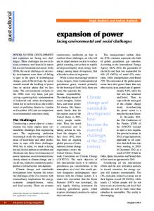
Fig. 6. Waveforms of the load currents shown in Table II. Each waveform represents one period of the fundamental frequency (20 ms).
In Table II, the total rms value and the total harmonic distortion (THD) of the current are also given as percentages of the fundamental frequency current. The current waveforms of the loads are shown in Fig. 6. Load A is a computer load, load B is a typical ac–dc–ac drive with large inductance on the dc side, load C is a drive with capacitance on the dc side without a series choke, load D is a drive with capacitance on the dc side and a 5% series choke, and load E is a drive with relatively high 11th harmonic. Load A was measured in a subdistribution board in an office building at the Aristotle University of Thessaloniki, Thessaloniki, Greece, while the other loads were measured in distribution boards in the plants of a textile-spinning mill in Greece. of (16) can be calculated by dividing an value Factors value. given in Table II with the respective
DEMOULIAS et al.: AMPACITY OF LOW-VOLTAGE POWER CABLES
TABLE III CALCULATED AMPACITY DERATING FACTOR OF CABLES SHOWN IN FIG. 1 AND TABLE I, FOR THE LOAD TYPES SHOWN IN TABLE II. EQUAL MAXIMUM LOSSES PER CONDUCTOR WERE ASSUMED
TABLE IV CALCULATED AMPACITY DERATING FACTOR OF CABLES SHOWN IN FIG. 1 AND TABLE I, FOR THE LOADS SHOWN IN TABLE II. ACTUAL LOSSES PER CONDUCTOR WERE ASSUMED
589
medium-sized cables, the effect of asymmetry in the losses is negligible. The above definition of the derating factor relates the total rms value of a distorted current to the rms value of a current of fundamental frequency, whereas the derating factor given in [10] and [12] is related to the fundamental frequency components of the two currents. Thus, the definition followed in this paper yields larger derating factors than those that would have been calculated, if the definition given in [10] and [12] was adopted. In practical situations, an engineer knows the type of a load as well as the maximum rms current it demands. On the contrary, he or she rarely knows the harmonic signature of the current and, thus, the fundamental harmonic component. Using the definition of the derating factor given in (17), the engineer must simply multiply the derating factor with the ampacity values given in [7] to obtain the new permissible ampacity. VII. VALIDATION OF THE MODEL
Table III shows the ampacity derating factors for all load types shown in Table II and for various cables. For a cable with mm and a load with high triplen cross section harmonics—such as type A—the ampacity should be derated by 46%. Even for cables with relatively small cross sections, such as mm , derating can be as high as 29% when used for the feeding computer loads. The results also show that a series choke applied in a variable speed drive can lead to larger derating factors. This is evident by comparing load types C and D for all cable sizes and types. When triplen harmonics are present, the cross section of the neutral conductor plays an important role as can be seen by commm with cable mm and paring cable mm with cable mm for load also cable type A. The ampacity derating factor of cables with a reduced neutral cross section is smaller by approximately 10%. When triplen harmonics are not present or are relatively small, as is the case for load types B, C, D, and E, the cross section of the neutral conductor plays an insignificant role in the derating of the cable’s ampacity. Load types B and E have the same THD but different harmonic profiles as shown in Table II. Load type E needs a slightly larger ampacity derating than load type B, because its spectrum is toward higher frequencies. Hence, not only the THD but, the harmonic signature is of importance in cable derating, as also shown in [10] and [12] for pipe-type cables. The derating factors in Table III were calculated under the assumption that the losses of each phase conductor of the cable are equal to the maximum losses. If instead of that assumption the actual losses of the phase conductors—as they appear in Figs. 2 to 3—were used, the derating factors would be as shown in Table IV. It is easily noticed by comparing Tables III and IV that the asymmetry in conductor losses leads to approximately 1.0–1.5% smaller derating factors in large cables. In small- and
The model developed in this paper was validated by comparison to 1) ampacity derating as mentioned in the IEEE Standard 519-1992, 2) the simplified mathematical model developed in [10] and 3) measurements of cable losses in a lighting installation. A. Comparison of IEEE Standard 519-1992 According to IEEE Standard 519-1992 [9], the cable ampacity should be derated when harmonic currents are present. Ampacity derating factors for low-voltage (600-V) cables and for a specific harmonic signature are given in Fig. 6-1 of this standard. The ratios, the definition of ampacity derating factor, and the values of the derating factors for various cable cross sections were derived from [8]. For example, according to [8] and [9], a derating factor of 0.966 should be applied to a three-phase system consisting of three THHN- or THWN-type cables of 250-kcmil cross section when balanced three-phase currents flow with harmonic signature as given in [9, Fig. 6-1]. The specific value of the derating factor is valid under the following assumptions [8]. 1) No metallic trays are present in the neighborhood of the cable system. 2) The cables are placed in close triangular form so that the proximity effect is maximized. 3) The value of the fundamental current is equal to the cable’s rated 60-Hz current. The cable system of [9] was examined using the FEM model developed in this paper. The geometry is shown in Fig. 7. ratios of the cable conductors Table V shows the as calculated using the FEM model of this paper and as given in [8] for a number of harmonic frequencies (the fundamental frequency is 60 Hz). By comparing the two columns of Table V, the difference between the two approaches is always less than 5%. values, as calculated by the current Inserting the FEM model, in the equation that defines the ampacity derating which is very close to factor in [8], we find that given in [8] and [9].
590
IEEE TRANSACTIONS ON POWER DELIVERY, VOL. 22, NO. 1, JANUARY 2007
Fig. 7. Geometry and dimensions of three 250-kcmil THHN cables placed in close triangular form.
R =R
Fig. 8. Geometry and dimensions of the simulated pipe-type cable. All dimensions are in millimeters.
TABLE VI CONTRIBUTION TO AC RESISTANCE DUE TO SKIN EFFECT FOR THE CABLE ARRANGEMENT SHOWN IN FIG. 8
TABLE V RATIOS OF THE CONDUCTORS SHOWN IN FIG. 7
It should be noted that the derating method given in [8] is very conservative, since it is based on the conductor’s dc rating, not values are applied in the 60-Hz ac rating. If the same , 990 will result for the same (17), a derating factor of harmonic signature. B. Comparison to a Simplified Mathematical Model The simplified mathematical model developed in [10] includes the proximity effect due to currents in the neutral conductor and in metallic pipes around the cables. To compare the two methods, the cable arrangement presented in the example shown in [10] was modeled using the method described in this paper and is shown in Fig. 8. The dimensions and other cable operational parameters are extracted was assumed from [10]. A specific conductance of for the pipe. for the conductors and According to [10] and [11], the ratio can be expressed as (18) where is the frequency, is the contribution to ac resisis the contribution to ac resistance due to skin effect, is the tance due to proximity of other conductors, and contribution to ac resistance due to the proximity of pipe.
Fig. 9. x (increase in conductor resistance due to proximity to other conductors) as calculated by Meliopoulos and Martin (M-M) and the FEM model developed in this paper for the phase conductors (L1, L2, L3) and the neutral conductor.
Reference [10, (5)–(9)] can be used to calculate the above coefficients as a function of geometry and frequency. Table VI as calculated by using the equations shows the values of given in [10] and the FEM model in this paper. It is evident that the difference between the two approaches is negligible since the maximum discrepancy is of the order of 1.3%. as calculated using the two Fig. 9 shows the values of methods. The relatively large discrepancies between the two models are due to the following reasons: first, the Meliopoulos and Martin approach, as expressed by [10, (7)], is based on a respective
DEMOULIAS et al.: AMPACITY OF LOW-VOLTAGE POWER CABLES
591
Fig. 12. Measurement setup.
Fig. 10. x (increase in conductor resistance due to proximity to other conductors) as calculated by Meliopoulos and Martin (M–M) and the FEM model developed in this paper for the phase conductors (L1, L2, L3) assuming that the 3rd and 9th harmonic form a balanced system.
current with: 1) fundamental (60 Hz)—350 A; 2) 3rd harmonic—80 A; 3) 5th harmonic—12 A; 4) 7th harmonic—12 A. The ampacity derating factor is calculated to be equal to 0.899 if the method in [10] is followed, and equal to 0.8961, if the method presented in this paper is followed. Although there is a large difference between the two methods in the calculation of the cable resistance at zero-sequence harmonics, the calculated derating factors are almost identical, due to the difference in the definition of the derating factor as mentioned in clause VI. C. Comparison to Measurements of Cable Losses
Fig. 11. R =R ratio as calculated by Meliopoulos and Martin (M–M) and the FEM model developed in this paper for the cable shown in Fig. 8.
Neher–McGrath [11] equation which, however, is accurate “for a system of three homogeneous, straight, parallel, and solid conductors of circular cross section arranged in equilateral formation and carrying balanced 3-phase current remote from all other conductors or conducting material” as stated in [11]. This means that the approach in [10] does not take into account the influence of the neutral conductor shown in Fig. 8. Second, the influence of the neutral conductor is significant when zero-sequence harmonics are present, because in such cases, the neutral conductor carries significant currents. It is therefore expected that the proxfactor, will be larger at zero-seimity effect and, hence, the quence harmonics. To demonstrate more clearly the difference between the two approaches, we assume that the currents at the 3rd and 9th harmonic do not form a zero-sequence system but phase displacement). In are balanced (i.e., they have , as calculated by the two methods, is shown such a case in Fig. 10. Since in this case the neutral conductor carries only eddy currents, the proximity effect is essentially only among the phase conductors. For this reason, the discrepancies between the two methods are much smaller. It is therefore evident that since the 3rd and 9th are zerosequence harmonics, the method presented in this paper is closer to reality. ratio as calculated by the two Fig. 11 shows the methods. Now assuming that the cable shown in Fig. 8 carries a
The losses in a cable feeding lighting dimmers were measured and compared to calculations based on the model presented in this paper. The measurement setup was as follows: The theatrical lighting in the Royal Theatre in Thessaloniki, Greece, is controlled by several single-phase dimmers. The dimmers are fed by a local distribution switchboard that is connected to the main mm cable, as shown in Fig. 12. switchboard via a J1VV The cable is located at a distance away from other cables and metallic trays for the largest part ( 90 m) of its length. Specific lights were turned on so as to form a three-phase symmetrical load. Then, a dimming level that caused high levels of triplen current harmonics was selected. Two identical measuring instruments (MI1 and MI2 in Fig. 12) were used for the measurement of the active power at the beginning and at the end of the cable, respectively. By subtracting the power recordings of the two instruments, the cable losses can be calculated. The measuring instrument was the TOPAS 1000 model from LEM Norma GmbH. One instrument was used to monitor the voltage and current for each of the four cable conductors with a sampling frequency of 6.4 kHz. The voltages are referenced to the protective earth conductor (PE). The power measurement error lies between 0.2% and 2.2% of the measured value, depending on the frequency and magnitude of the current. Large errors occur at frequencies beyond 1.25 kHz and at currents that are 1% of the rating of the current sensor. At 50 Hz and at currents that are equal to the current sensor’s rating, the error is small (0.2%). The instruments monitor the active power at each harmonic frequency and log the values every 40 ms. Both instruments were set up by the same personal computer. Thus, the clocks of the two instruments were synchronized, so that logging is made at the same time.
592
IEEE TRANSACTIONS ON POWER DELIVERY, VOL. 22, NO. 1, JANUARY 2007
TABLE VII HARMONIC ANALYSIS OF THE MEASURED PHASE AND NEUTRAL CURRENTS AT TWO TIME INSTANCES. THE FUNDAMENTAL FREQUENCY IS 50 Hz
Fig. 14. Calculated and measured cable losses at a first time instant as shown in Table VII. The cable is design J1VV 4 95 mm and 110 m long.
2
Fig. 13. Variation with harmonic order of the Rh/Rdc ratio of the phase and neutral conductors of a 4 95 mm cable.
2
Measurements were compared with results obtained by using the FEM model for two different time instances that correspond to two different current harmonic signatures. Table VII shows the harmonic components of the phase and neutral conductor currents and the total rms values of the current at each instant. Small asymmetries in the phase currents cause small currents in the neutral conductor even at nontriplen harmonics. The cable losses can be calculated by the following formula: (19) is the rms value of the harmonic current in phase where , is the resistance of phase conductor at the th haris the resistance of the neutral conductor at the monic, and th harmonic. and ratios, as calculated using the The FEM model developed in this paper, are shown in Fig. 13. at the operating temperature of To calculate the losses, the cable must be known. According to manufacturer’s data, at 20 C. Using an infrared thermometer, the cable temperature was measured at various points along its length. The temperature varied from 42 C to 47 C. For the calculations, a mean temperature of 45 C was assumed.
Fig. 15. Calculated and measured cable losses at a second time instant as shown in Table VII. The cable is design J1VV 4 95 mm and 110 m long.
2
Figs. 14 and 15 show the measured and calculated cable losses at each harmonic frequency for the first and second time instance, respectively. It can be noticed that the calculations are in good agreement with the measurements, since the maximum discrepancy between them is less than 10% of the respective measured value. The very good agreement at the zero-sequence harmonics, which validates the method presented in this paper, is also of special interest. VIII. CONCLUSION resistance ratio of four-conductor, PVC-insuThe lated low-voltage (0.6/1.0-kV) power distribution cables, as they are specified by CENELEC Standard HD603, was calculated for frequencies that correspond to the odd harmonics from the 1st up to the 49th. It was shown that, due to cable geometry, the phase conductors do not present equal losses but the losses of one or two conductors can be larger than the losses of the rest. The ac resistances were defined in a way to reflect the maximum losses per conductor. ratio increases with frequency It was shown that the and that this increase is much larger when zero-sequence harratio of monics (3rd, 9th, 15th, etc.) are present. The the neutral conductor was shown to increase with frequency too, but not as much as that of the phase conductors.
DEMOULIAS et al.: AMPACITY OF LOW-VOLTAGE POWER CABLES
An ampacity derating factor was defined and calculated for five typical cable configurations and for five typical nonsinusoidal loads. The derating factor was based on the total rms values of a distorted current and of a current of fundamental frequency that cause the same power losses in the cable. It was shown that when triplen harmonics are present, the derating of the ampacity is in the range of 29% to 46%, depending on the cross section of the conductor. A larger ampacity derating is required as the phase-conductor cross section increases. When the neutral conductor has reduced the cross section, then the derating should be larger than when it has the same cross section as the phase conductors. This implies that for feeding large computer loads (such as banks or large office buildings) and to avoid a large derating of the cable ampacity, two separate cables should be used: a three-conductor cable for the phases and another single core cable for the neutral. Industrial loads are mainly three-phase loads with an insignificant amount of triplen harmonics. Such loads require ampacity derating in the range of 0.1% to 12%, depending on the cross section of the conductor. The cross section of the neutral conductor is not significant for these loads. It was shown that not only the THD but also the harmonic signature of the load current is important. When the current contains harmonics at higher frequencies, then the ampacity requires larger derating. The asymmetry in the losses of the conductors leads to approximately 1.0–1.5% larger derating for the ampacity of the cable. The validity of the model was verified by comparison with the data given in IEEE Standard 519-1992, mathematical models in the literature, and measurements in real installation.
ACKNOWLEDGMENT The authors would like to thank the authorities of the Royal Theatre, Thessaloniki, Greece, for granting permission to conduct the measurements in the lighting installation.
593
[8] D. E. Rice, “Adjustable speed drive and power rectifier harmonicstheir effect on power system components,” IEEE Trans. Ind. Appl., vol. IA-22, no. 1, pp. 161–177, Jan./Feb. 1986. [9] IEEE Recommended Practices and Requirements for Harmonic Control in Electrical Power Systems, IEEE Std. 519-1992. [10] A. P. Sakis Meliopoulos and M. A. Martin, Jr., “Calculation of secondary cable losses and ampacity in the presence of harmonics,” IEEE Trans. Power Del., vol. 7, no. 2, pp. 451–457, Apr. 1992. [11] J. H. Neher and M. H. McGrath, “The calculation of the temperature rise and load capability of cable systems,” AIEE Trans., vol. 76, pp. 752–772, Oct. 1957. [12] J. A. Palmer, R. C. Degeneff, T. M. McKernan, and T. M. Halleran, “Determination of the effect of harmonics on pipe-type power cable AC/DC resistance ratios,” IEEE Trans. Magn., vol. 29, no. 2, pp. 1427–1433, Mar. 1993. [13] J. A. Palmer, R. C. Degeneff, T. M. McKernan, and T. M. Halleran, “Pipe-type cable ampacities in the presence of harmonics,” IEEE Trans. Power Del., vol. 8, no. 4, pp. 1689–1695, Oct. 1993. [14] A. Hiranandani, “Calculation of cable ampacities including the effects of harmonics,” IEEE Ind. Appl. Mag., vol. 4, no. 2, pp. 42–51, Mar./ Apr. 1998. [15] Distribution cables of rated voltage 0,6/1 kV, CENELEC Std. HD603 S1:1994/A1:1997. [16] “Opera-2D User Guide,” Vector Fields Ltd., 2004. [17] NFPA 70, National Electrical Code, 2005 Edition Aug. 5, 2004, Published by Nat. Fire Protection Assoc.
Charis Demoulias (M’95) was born in Katerini, Greece, on July 23, 1961. He received the Diploma and Ph.D. degrees in electrical engineering from the Aristotle University of Thessaloniki, Thessaloniki, Greece, in 1984 and 1991, respectively. He was a Consultant in the areas of industrial electrical installations, electrical energy savings, and renewable energy sources. Currently, he is a Lecturer with the Department of Electrical and Computer Engineering, Electrical Machines Laboratory, Aristotle University of Thessaloniki. His research interests are in the fields of power electronics, harmonics, electric motion systems, and renewable energy sources.
REFERENCES [1] J. S. Subjak and J. S. McQuilkin, “Harmonics-causes, effects, measurements, and analysis: An update,” IEEE Trans. Ind. Appl., vol. 26, no. 6, pp. 1034–1042, Nov./Dec. 1990. [2] V. E. Wagner et al., “Effects of harmonics on equipment. Report of the ieee task force on the effects of harmonics on equipment,” IEEE Trans. Power Del., vol. 8, no. 2, pp. 672–680, Apr. 1993. [3] G. Carpinelli, P. Caramia, E. Di Vito, A. Losi, and P. Verde, “Probabilistic evaluation of the economical damage due to harmonic losses in industrial energy system,” IEEE Trans. Power Del., vol. 11, no. 2, pp. 1021–1028, Apr. 1996. [4] A. E. Emanuel and M. Yang, “On the harmonic compensation in nonsinusoidal systems,” IEEE Trans. Power Del., vol. 8, no. 1, pp. 393–399, Jan. 1993. [5] J.-S. Lai and T. S. Key, “Effectiveness of harmonic mitigation equipment for commercial office buildings,” IEEE Trans. Ind. Appl., vol. 33, no. 4, pp. 1104–1110, Jul./Aug. 1997. [6] J. J. M. Desmet et al., “Analysis of the neutral conductor current in a three-phase supplied network with nonlinear single-phase loads,” IEEE Trans. Ind. Appl., vol. 39, no. 3, pp. 587–593, May/Jun. 2003. [7] Electrical Installations of Buildings—Part 5: Selection and Erection of Electrical Equipment—Section 523: Current-Carrying Capacities in Wiring Systems, CENELEC Std. HD384.5.523, 2001, S2.
Dimitris P. Labridis (S’88–M’90–SM’00) was born in Thessaloniki, Greece, on July 26, 1958. He received the Dipl.-Eng. and Ph.D. degrees in electrical engineering from the Department of Electrical and Computer Engineering at the Aristotle University of Thessaloniki, Thessaloniki, Greece, in 1981 and 1989, respectively. From 1982 to 2000, he was a Research Assistant with the Department of Electrical and Computer Engineering, Aristotle University of Thessaloniki. where he became Lecturer, and Assistant Professor, and is currently an Associate Professor. His research interests are power system analysis with a special emphasis on the simulation of transmission and distribution systems, electromagnetic and thermal field analysis, artificial-intelligence applications in power systems, power-line communications, and distributed energy resources.
594
Petros S. Dokopoulos (M’77) was born in Athens, Greece, in 1939. He received the Dipl. Eng. degree from the Technical University of Athens in 1962 and the Ph.D. degree from the University of Brunswick, Brunswick, Germany, in 1967. From 1962 to 1967, he was with the Laboratory for High Voltage and Transmission, University of Brunswick; from 1967 to 1974, he was with the Nuclear Research Center, Julich, Germany, and from 1974 to 1978, he was with the Joint European Torus, Oxfordshire, U.K. Since 1978, he has been Full Professor with the Department of Electrical Engineering, Aristotle University of Thessaloniki, Thessaloniki, Greece. He was a Consultant to Brown Boveri and Cie, Mannheim, Germany; Siemens, Erlangen, Germany; Public Power Corporation, Athens; the National Telecommunication Organization, Athens, and construction companies in Greece. His research interests are dielectrics, power switches, power generation, transmission, and distribution.
IEEE TRANSACTIONS ON POWER DELIVERY, VOL. 22, NO. 1, JANUARY 2007
Kostas Gouramanis (M’02) was born in Athens, Greece, on September 22, 1979. He received the diploma in electrical engineering from the Department of Electrical and Computer Engineering, Aristotle University of Thessaloniki, Greece, in 2003, where he is currently pursuing the Ph.D. degree. His research interests are in the fields of power electronics, power system harmonics, and power quality. Mr. Gouramanis is a member of the Society of Professional Engineers of Greece.