AMPERE Newsletter 333
Trends in RF and Microwave Heating http://www.ampere‐newsletter.org
Issue 92
April 26, 2017
In this Issue: Page Emerging microwave‐plasma technologies for chemical processes J. F. de la Fuente, A. A. Kiss, M. T. Radoiu, G. D. Stefanidis Computer‐aided analysis and optimization of microwave heating systems V. V. Komarov Green‐Tech microwave studies at Tohoku University N. Yoshikawa, C. C. Lee, M. Sunako, K. Kawahira, S. Taniguchi Rendering of waste by application of microwave energy R. Parosa Microwave flash sintering Yu. V. Bykov, A.G. Eremeev, S.V. Egorov, V.V. Kholoptsev, I.V. Plotnikov, K.I. Rybakov*, A.A. Sorokin Microwave drying of seeds of agricultural interest for Ecuador Á. H. Moreno, R. Hernández, I. Ballesteros Emerging applications for microwave technology in chemistry, polymers and waste T. Asgarli, M. Reichmann, N. Voit Ricky’s Afterthought: Beamed wireless power‐transfer using a dynamic metasurface aperture Ricky Metaxas
2 10 14 18 24 28 33 36
AMPERE 2017 and other upcoming events
37
Call for papers
38
Previous issues and papers of AMPERE Newsletter are available at http://www.ampere‐newsletter.org ISSN 1361-8598
AMPERE Newsletter
Issue 92
April 26, 2017
Emerging Microwave‐Plasma Technologies for Chemical Processes Javier F. de la Fuente1, Anton A. Kiss2,3, Marilena T. Radoiu4, Georgios D. Stefanidis5* 1
Process & Energy Laboratory, Delft University of Technology, Leeghwaterstraat 39, 2628 CB, Delft, The Netherlands AkzoNobel – Supply Chain, Research & Development, Process Technology SRG, Zutphenseweg 10, 7418 AJ Deventer, The Netherlands 3 Sustainable Process Technology Group, Faculty of Science and Technology, University of Twente, PO Box 217, 7500 AE, Enschede, The Netherlands 4 Independent consultant 5 Chemical Engineering Department, Katholieke Universiteit Leuven, Celestijnenlaan 200f, 3001 Leuven (Heverlee), Belgium 2
Abstract Microwave plasma (MWP) technology is currently being used in application fields such as semiconductor and material processing, diamond film deposition and waste remediation. Specific advantages of the technology include the enablement of a high energy density source and a highly reactive medium, the operational flexibility, the fast response time to inlet variations and the low maintenance costs. These aspects make MWP a promising alternative technology to conventional thermal chemical reactors provided that certain technical and operational challenges related to scalability are overcome. Herein, an overview of state-of-the-art applications of MWP in chemical processing is presented (e.g. stripping of photo resist, UV-disinfection, waste gas treatment, plasma reforming, methane coupling to olefins, coal/biomass/waste pyrolysis/gasification and CO2 conversion). In addition, two potential approaches to tackle scalability limitations are described, namely the development of a single unit microwave generator with high output power (> 100 kW), and the coupling of multiple microwave generators with a single reactor chamber. Finally, the fundamental and engineering challenges to enable profitable implementation of the MWP technology at large scale are discussed. expected to have an increasing share in the future energy scene – that is, a large fraction of the energy needed for chemical conversion processes can be obtained from these sources during peak electricity production periods. This falls within the so-called power-to-chemicals approach2, whereby greenhouse gases and/or water are converted into hydrocarbons by means of surplus electric power. In this context, plasma reactors represent a novel alternative technology due to certain processing benefits such as: fast process dynamics, process flexibility, no need for catalyst use in many processes, no need for (bulky and costly) gas-fired furnaces, low maintenance cost, and high quality products (low byproducts formation). In this work, we focus on microwave plasma (MWP) assisted reactors, which appear to be one of the most promising plasma reactor types. The principal advantage of MWP over other discharges is that it does not require electrodes, which must be placed inside the reactor leading to operational issues,
1. Introduction A sustainable and green economy represents one of the major challenges of contemporary society. It involves mostly the reduction of waste generation, but also the optimization of raw material consumption in order to mitigate current alarming pollution problems, and lower the energy requirements of industrial conversion processes. For the chemical industry to progress towards a sustainable economy, novel waste-to-product approaches need to be developed to reduce the dependency on fossil fuels-based raw materials. Carbon Capture & Utilization (CCU) is an emerging concept, which utilizes waste (e.g. greenhouse gases) as chemical feedstock to produce valuable products1. In most cases, however, the required energy input to transform waste into products tends to be rather high, making the re-utilization process unprofitable. Renewable energy sources, such as wind and solar power, are 2
AMPERE Newsletter
Issue 92
April 26, 2017
generation cost ~2.3 $/kg H2 (assuming 0.06 $/kWh). This value is close, within a factor 2, to the reported industrial cost of H2 production (representative value: 1.5 $/kg H2)9 through the mature and highly integrated and optimized process of steam reforming of natural gas in high temperature furnaces. Another example is reported by Uhm et al. (2014)5, in which the gasification of brown coal in a pilot-scale setup was studied, obtaining cold gas efficiency (CGE) values up to 84%, while conventional gasifiers10 have CGE values between 70-80%.
such as regular maintenance (replacement) due to erosion3. The high frequencies at which MWP systems are operated produce a large fraction of electrons, i.e. high electron densities, and high electron temperature (energy) compared to other plasma sources. This results in high concentrations of active species rendering MWP an ideal highly reactive medium for chemical reactions. Here we present the state-of-the-art of MWP at laboratory stage, existing industrial chemical applications, current technical and operational limitations, and an overview of the fundamental and engineering challenges for further development of the MWP technology. Finally, some promising potential applications, which mainly concern high temperature processes, such as pyrolysis, gasification and reforming of organic waste, biomass and fossil fuels are discussed. Overall, this paper intends to set up a roadmap describing the main requirements and the next steps needed for the implementation of the MWP technology in the chemical manufacturing industry.
36 cm
2. MWP technology: State‐of‐the‐art 2.1. Laboratory stage
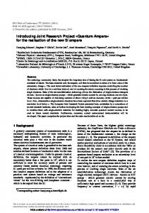
A remarkably broad range of chemical applications at laboratory-scale have been explored in different MWP systems with the exception of biomass gasification for syngas production, which has been investigated both at laboratory scale4 and in medium-scale plants5,6. Concerning chemical manufacturing applications, several processes are highlighted due to the large number of research studies (see Table 2 in Ref. [7]). These include plasma-assisted reforming, biomass gasification and pyrolysis, H2 production, and CO2 utilization. Figure 1 shows an atmospheric air microwave plasma at different values of net input power used for biomass gasification purposes at Delft University of Technology. Herein, certain processes should be acknowledged due to the notably good performance shown in MWP reactors. As reported by Jasinski et al.8, H2 generation via plasma-assisted dry reforming of methane can be carried out at a specific energy consumption of ~3 kWh/m3 H2, and a H2
Figure 1. Atmospheric air microwave plasma at 2, 2.5 and 3 kW microwave power, from left to right.
2.2. Industrial applications of MWP technology The applications of MWP at industrial-scale have been previously discussed in the literature11. In summary, the main industrial applications include photoresist stripping in semiconductor manufacturing, deposition of barrier layers in PET bottles, high rate deposition process of quarts on polycarbonate windows, plasma photo curing of paintings applied to the automotive industry, UV disinfection for water treatment, waste gas treatment for decomposition of fluorine-based components such as CF4, C2F6, CHF3, and SF612 or ammonia, and plasma reforming to increase efficiency in wood gas engines. Table 1 presents the latest industrial applications of MWP together with a brief description of the main features of each process. Most of the future industrial applications of the MWP technology will be relevant to high 3
AMPERE Newsletter
Issue 92
April 26, 2017
temperature processes for chemical synthesis and (oxygenated) fuels conversion including pyrolysis, gasification and reforming of organic waste, biomass, and fossil fuels. Other application fields
in which MWP will play a role are water and air purification, material synthesis (nano-particle production, diamonds, textiles) and biomedicine (cancer treatment, wound healing, disinfection).
Table 1. Summary of novel MWP processes for chemical applications. PROCESS (COMPANY) BIOMASS GASIFICATION (Plasma2Energy)6
CARBON FIBER MANUFACTURING (RMX Technologies)13
PECVD OF Si3N4 ON MULTI‐CRYSTALLINE SILICON SOLAR CELLS14
DESCRIPTION
MAIN FEATURES
- Medium‐scale plant for biomass gasification. - It run for four years. - It exploited the concept of coupling multiple microwave generators to a single gasification chamber. - The plant consumed only 20% of the energy generated.
Input microwave power = 30 kW (plasmatrons) Pressure = 1 bar Annual Biomass Capacity = 3.3 kton Selectivity (H2) = 50‐52% Annual Production = 1830 m3 ethanol & 253 m3 diesel fuel Maintenance: 5 years Lifetime: 25 years
- Low‐pressure microwave plasma enhanced the oxidation and carbonization steps. - Reduction in the residence time and the equipment size by 1/3. - Energy requirements were reduced by 75% and manufacturing costs by 20% compared to conventional one.
Input MW power = 30 kW (915 MHz) Pressure = 10 mbar Reactor size: Diameter = 0.05 m, Length = 4 m Energy efficiency = 17 kWh/kg carbon fiber
- Deposition of silicon nitride anti‐ reflective layers on solar cell wafers by plasma enhanced carbon vapor deposition (PECVD).
Input microwave power = 2 x 4 kW (pulsed) Pressure = 0.01‐1 mbar Reactor size: Diameter = 0.02 m, Length = 1.5 m Production = 1500 solar cells wafers per hour
TREATMENT OF CHRONIC - Wound healing by reduction of microbial load and by modifying the WOUNDS wound microenvironment. (Adtec Europe SteriPlas)15 - Working gas is Argon, which ensures the reproducibility of generated active agents. PRODUCTION OF SYNTHETIC DIAMOND MPECVD (ASTeX)16
- Synthetic diamond growth from the gas phase by microwave‐plasma enhanced vapor chemical deposition (MPECVD). - Synthesis diamonds are presented as a much affordable option over naturally mined diamonds.
4
Input microwave power = 200 W Working gas = Argon, purity 99.95% Operating temp range = 10‐30 oC
Frequency = 915 MHz, Power = 90 kW Pressure = 180 torr Gas temperature = 4000 K Working gas = H2 + 1‐5% CH4 Deposition rate = 1 g/h Annual production rate = 214,300 carats (10 reactors) Diamond production cost = 14 $/carat
AMPERE Newsletter
Issue 92
April 26, 2017
and water are the most commonly used gases, (2) design of a novel reactor configuration such as “Vortex/Tornado-type” or multi-point microwave coupling, and (3) combination of microwave and other fields (e.g. radio-frequency).
3. State of development and outlook 3.1. Current status of the technology 3.1.1. Microwave generator The largest single-unit continuous wave (CW) microwave generator, namely magnetron, presents a limitation of maximum output power of 15 kW at a frequency of 2450 MHz and 100 kW at 915 MHz. From an economic and regulatory point-of-view, there are two commercially preferable frequencies on the ISM bands, 915 MHz (L-band) and 2450 MHz (S-band) that can be used for MWP reactors. To date, most of the work with MWP has been done at the standard microwave frequency of 2450 MHz. In the case of the 915 MHz frequency, the waveguide components are characterized by larger sizes (about three times larger than those of one at 2450 MHz), which makes these microwave generators more costly compared to 2450 MHz generators.
3.1.3. Cooling of the plasma reactor MWP is characterized by high power densities, which enable MWP reactors to achieve energy efficiencies up to 90%. As a result, one of the major technical challenges is the cooling of the reactor due to the high values of power input per unit wall area (W/cm2), which increases significantly the chance of reactor melting (quartz tube). Hence, MWP reactors require carefully designed cooling systems to ensure a continuous operation. The most common cooling techniques are forced-air/N2 in combination with cooling water jacket-type18 surrounding the plasma reactor. When the power input per unit wall area becomes relatively high (> 40 W/cm2)3, a common measure of protection of the reactor wall is the use of high-speed tangential gas injection (swirl flow) to confine the plasma at the core of the reactor by creating a tornado/vortex gas motion, which isolates the reactor wall from the plasma column.
3.1.2. Plasma ignition, stability and uniformity Plasma is ignited when the applied electric field strength overcomes the breakdown voltage of the working gas, which is called electric breakdown17. When low pressure MWP is considered, the required field strength to ignite and maintain the plasma is less demanding compared to MWP at atmospheric pressure. For large scale chemical applications, uniformity and stability become imperative in the production process, as it is highly important to ensure a constant and reproducible product composition. One of the major challenges for use of the MWP technology is its inherent instability, which has implications in reproducibility of the results. When operating MWP at atmospheric pressure and high power conditions, plasma stability depends mostly on the interplay between input microwave power and flow dynamics (working gas flow rate, feed gas composition, swirl flow). Additionally, operating at a minimum reflected power implies operation very close to or at unstable conditions that can lead to plasma loss or fluctuations (non-uniform). In this regard, there are a number of practical measures to improve plasma stability: (1) addition of a carrier/working gas; argon, helium, nitrogen, air
3.1.4. Reactor material As already stated, one of the main features provided by MWP is the high energy density, which also implies high temperatures inside the reactor. In this regard, the material of the reactor is a crucial aspect in MWP operation. At lab-scale, the most commonly used material is quartz, which seems unsuitable for commercial applications due to its fragility. Therefore, other materials such as ceramics (alumina-based), aluminium oxynitride (melting point above 2000 oC) or silicon carbide can be used to build large size MWP reactors. The latter has already been used in a plasma gasification unit19. Moreover, in the pilot-scale setup developed by Uhm et al.5, alternative materials such as HACT180 (fire-resistance ceramic) and INCT120 (insulating-cement) were used to form the inner and outer layers of the MWP reactor respectively, showing great performance at temperatures up to 1800 oC. 5
AMPERE Newsletter
Issue 92
April 26, 2017
chamber, or (2) developing single unit microwave sources with > 100 kW output power at lower frequencies (e.g. 433 MHz). The first approach has already been explored for a medium-scale gasification plant as shown in Sanchez A.L. (2010)6. To increase the capacity, multiple 20 kW microwave plasmatrons were arranged around and along a single MWP gasification chamber. A schematic representation is presented in Figure 2. As a final remark, the MWP gasification system reported in Sanchez A.L. (2010)6 was designed to have maintenance every 5 years and a lifetime of 25 years, which is common practice in the chemical process industry.
3.1.5. Process control and safety MWP-based processes show remarkably fast dynamics, in which most of the events take place in the micro/milli-second range. Such dynamics require demanding continuous process control tools that are capable of adjusting process parameters within a response time of milliseconds. The input power is the most important process variable, as it influences directly the absorbed energy by the plasma and consequently the temperature of the reactor. The gas flow rate largely affects reactor stability as low flow rates can lead to severe increase in the specific energy input (SEI, J/m3), i.e. the ratio between the input power and the inlet flow rate, causing rupture of the reactor. When the flow rates are excessive, plasma is extinguished due to the drop of SEI. Control of the operating pressure is particularly important when working with low-pressure MWP, as it influences both plasma ignition and sustenance. With respect to safety, the primary concern is related to exposure of operators and/or fuel to microwave radiation. Furthermore, considering the possible risk of reactor breaking, it is advisable to operate MWP reactors within a properly ventilated area to contain the hazard of a gas leakage. 3.2. Scalability When evaluating the development of a new process, the production capacity represents the main design guideline, thus dictating the equipment requirements. Bulk chemicals are commonly produced on a very large scale, implying the need to operate at considerably high throughput and therefore demanding high energy input. A pilot-scale MWP gasification unit was developed by Uhm et al.(2014)5. In their work, two microwave generators of 75 kW output each were attached to the gasification chamber and enabled inlet flow rates of 2.2 ton coal/day with respective throughput of 1.9 ton syngas/day corresponding to a total calorific value of 0.5 MWth. To our knowledge, there are two possibilities to address the high input microwave power required to sustain the plasma at rather high throughput: (1) coupling multiple microwave generators to a single reactor
Figure 2. Schematic representation of multiple microwave generators attached to a single reactor6. Note that each of the black elements represents a 20 kW microwave plasmatron.
The second alternative envisages the development of single unit microwave sources with >100 kW output power. Within the microwave ISM frequencies for industrial processing, the frequency band 433.05 – 434.79 MHz (central frequency 433.92 MHz) appears to be the most interesting one for scale-up. Currently, there are no reported industrial applications operating at 433.96 MHz. However, according to magnetron manufacturers, CW magnetrons operated at this frequency can be designed to deliver much higher microwave power levels than the L-band (896 6
AMPERE Newsletter
Issue 92
April 26, 2017
MHz, 915 MHz, 922 MHz and 929 MHz) magnetrons namely, between 0.5 and 1 MW. The design of high power 433.96 MHz equipment should consider the development not solely of the magnetron and the HV DC power supply, but also all the high power rated WR2100 waveguide components (isolators, impedance tuners etc.) required to run industrial applications.
and also form an attractive strategy to overcome rapid changes in the market demand. Therefore, the production of syngas, hydrogen, acetylene and localized waste treatment represent some of the opportunities that MWP technology can address at present. Figure 3 presents in the form of a timeline the main scientific and engineering challenges to be addressed before MWP can be extensively used in the bulk chemical manufacturing industry. These challenges mainly concern: (1) development of higher than 100 kW microwave power sources and of effective plasma reactor designs that can be powered by multiple microwave generators to attain wide throughput range, (2) development of suitable reactor materials for MWP operation, (3) improvement of process reliability (controllability, stability and uniformity), and (4) development of chemical kinetic models that can be implemented into multidimensional multiphysics models for process design, optimization, and control.
3.3. Potential for chemical applications At the current technological state of MWP, the concept of modularized production seems to be the most promising approach to respond to: (1) the decentralized electricity generation via renewable energy sources, and (2) the present volatile markets. In this regard, the development of modular MWP units powered by locally generated renewable electricity for distributed manufacturing may, at least partially, change the current model of very large scale centralized industrial processing
Figure 3. Timeline for the implementation of MWP technology in chemical manufacturing industry.
with some successfully demonstrated industrial applications. Concerning chemical processing applications, high temperature processes, such as pyrolysis, gasification and reforming of organic waste, biomass and fossil fuels have the highest potential to benefit from MWP. However, it is imperative to perform research with medium-scale
4. Conclusions Microwave plasma (MWP) is one of the most promising enabling technologies for electricitybased reactors as regards the future partial electrification of the chemical industry. In this article, we have summarized the extensive research carried out on MWP at laboratory-scale combined 7
AMPERE Newsletter
Issue 92
April 26, 2017
14. Schlemm H, Mai A, Roth S, Roth D, Baumgartner KM, Muegge H. Industrial large scale silicon nitride deposition on photovoltaic cells with linear microwave plasma sources. Surf Coat Tech 174: 208-211 (2003). 15. Adtec, SteriPlas, http://www.adtecplasma.com/products.html#home. (accessed 25-09-2016). 16. Dischler B, Wild C. Synthetic Diamond: Manufacturing and Applications. Springer-Verlag (1998). 17. Fridman A. Plasma Chemistry. Cambridge: Cambridge University Press (2008). 18. de la Fuente JF, Moreno SH, Stankiewicz AI, Stefanidis GD. Reduction of CO2 with hydrogen in a nonequilibrium microwave plasma reactor. Int J Hydrogen Energ 41: 21067-21077 (2016). 19. Willis KP, Osada S, Willerton KL. Plasma gasification: Lessons learned at EcoValley WTE facility. 18th Annual North American Waste-to-Energy Conference (2010).
setups to quantitatively demonstrate the profitability, reliability and operational benefits of the technology, as already shown for biomass gasification. In parallel, work on development of (a) single-unit microwave sources with >100 kW output power (0.5-1.0 MW), (b) suitable reactor materials that can withstand harsh operating conditions, and (c) reaction kinetic models that can be implemented into multidimensional multiphysics reactor models appear to be key scientific and engineering challenges that need to be addressed to promote wider application of the technology to large scale operations. For further reading: 1. Styring P, Jansen D. Carbon capture and utilization in the green economy. Centre for Low Carbon Futures (2011). 2. Mennicken L, Janz A, Roth S. The German R&D program for CO2 utilization-innovations for a green economy. Environ Sci Pollut R 23: 11386-11392 (2016). 3. Ferreira CM, Moisan M. Microwave discharges fundamentals and applications. NATO ASI Series (1993). 4. Sturm GSJ, Munoz AN, Aravind PV, Stefanidis GD. Microwave-driven plasma gasification for biomass waste treatment at miniature scale. IEEE Trans. Plasma Sci 44: 670-678 (2016). 5. Uhm HS, Na YH, Hong YC, Shin DH, Cho CH. Production of hydrogen-rich synthetic gas from low-grade coals by microwave steam-plasmas. Int J Hydrogen Energ 39: 4351-4355 (2014). 6. Sanchez AL. Method and apparatus for plasma gasification of carbonic material by means of microwave radiation. US Patent: 2010/0219062 (2010). 7. de la Fuente JF, Kiss AA, Radoiu MT, Stefanidis GD. Microwave plasma emerging technologies for chemical processes. Journal of Chemical Technology & Biotechnology: (2017). 8. Jasinski M, Czylkowski D, Hrycak B, Dors M, Mizeraczyk J. Atmospheric pressure microwave plasma source for hydrogen production. Int J Hydrogen Energ 38: 11473-11483 (2013). 9. Dincer I, Zamfirescu C. Sustainable Hydrogen Production. Elsevier (2016). 10. Grabner M. Industrial Coal Gasification Technologies Covering Baseline and High-Ash Coal. Wiley-VCH (2014). 11. Kaiser M, Baumgartner KM, Mattheus A. Microwave plasma sources - Applications in industry. Contrib Plasm Phys 52: 629-635 (2012). 12. Radoiu M, Hussain S. Microwave plasma removal of sulphur hexafluoride. J Hazard Mater 164: 39-45 (2009). 13. Terry LW. System to continuously produce carbon fiber via microwave assisted plasma processing. US Patent: 8,679,592 (2014).
About the Authors Dr. Javier Fernandez de la Fuente will soon receive his Ph.D. at Delft University of Technology in the Netherlands on the application of microwave plasma technology to convert CO2 into high value chemicals. He completed his M.Sc. degree in Chemical Engineering at University of Valladolid (Spain) in 2012. He has broad experience as a R&D engineer, mostly focused on the production of liquid fuels through alternative technologies. He worked on projects such as the design of a pervaporation unit to separate butanol from acetone‐ butanol‐ethanol (ABE) mixture as an alternative to distillation, and the start‐up and optimization of an ammonia fiber expansion pilot plant to pre‐treat wheat straw for the production of ethanol. Moreover, he explored a new approach to produce MCM‐41 for ibuprofen encapsulation by ultrasound‐assisted supercritical CO2 during his stage at Ruhr University of Technology in Germany. For more information: https://www.linkedin.com/in/javierfdelafuente E‐mail:
[email protected]
Dr. Anton Alexandru (Tony) KISS is a senior project manager at AkzoNobel ‐ Research, Development & Innovation, where he serves as an expert in fluid separation technologies, reactive‐ separation processes, process intensification, and integrated sustainable processes, as well as process modeling and simulation of industrial processes. He is also a part‐time professor of separation technology at the University of Twente (Sustainable Process Technology) in the Netherlands. He has published several textbooks, book
8
AMPERE Newsletter
Issue 92
April 26, 2017
chapters, patents, and more than 100 scientific articles. For his pioneering work and career achievements, he received in 2013 the Hoogewerff Jongerenprijs and the AkzoNobel Innovation Excellence Award. Kiss holds a PhD in chemistry and chemical engineering from the University of Amsterdam, and MS and BS degrees in chemical engineering from Babes‐Bolyai University of Cluj‐Napoca in Romania, and he was a post‐doctoral research fellow at Delft University of Technology (TU Delft) and the University of Amsterdam. He is a member of AIChE, IChemE, Society of Chemical Industry (SCI), European Society of Mathematical Chemistry (ESMC), Process Systems Engineering – The Netherlands (PSE‐NL), European Federation of Chemical Engineering (EFCE), and EFCE Working Party on Computer Aided Process Engineering (CAPE‐WP).
plasma etc. Her work has included engineering and development of novel industrial and scientific standard and custom products, such as Zenith Etch and Sirius6000 ‐ microwave plasma reactors for semiconductor gas cleaning, laboratory equipment such as MiniFlow 200, and Minilabotron 2000. Dr. Radoiu is also a member of several professional associations, including the Association for Microwave Power, Education and Research in Europe (AMPERE). For more information: https://www.linkedin.com/in/marilenaradoiu E‐mail:
[email protected] Prof. Georgios Stefanidis (KU Leuven, Belgium) received his chemical engineering education from the National Technical University of Athens (M.Sc.) and University of Gent (Ph.D.). His research interests revolve around process intensification, alternative energy forms and transfer mechanisms (mainly microwaves and plasma), biomass gasification and pyrolysis, catalytic reforming and partial oxidation of hydrocarbons and oxygenated fuels and CO2 utilization. He is co‐author of more than 60 peer‐review papers in the field of process intensification. * Corresponding author, E‐mail:
[email protected]
For more information: http://www.tonykiss.com E‐mail:
[email protected] Dr. Marilena Radoiu, Chartered Chemist (CChem) and Member of the Royal Society of Chemistry (MRSC), received her M.Sc. in Organic Technological Chemistry from the Polytechnic University of Bucharest in 1993 and her Ph.D. in Radiochemistry and Nuclear Chemistry from the same University in 1998. She has extensive work experience in different international academic and industrial environments. She has worked for 20 years in Romania, Canada, UK and France in the development of microwave‐assisted technologies with applications to chemical synthesis, biomass extraction,
9
AMPERE Newsletter
Issue 92
April 26, 2017
Computer‐Aided Analysis and Optimization of Microwave Heating Systems
Vyacheslav V. Komarov Department of Radio Electronics and Telecommunications, Institute of Electronic and Mechanical Engineering, Yuri Gagarin State Technical University of Saratov, Saratov, 410054, Russia
The application of microwave energy for thermal treatment of different materials and substances is a rapidly growing trend of modern science and engineering. Deep penetration of microwaves in dielectric media improves uniformity and intensifies the heating process. The variety of microwave heating devices like kitchen ovens, industrial plants, laboratory setups, and medical applicators is considerably large. Design and optimization of microwave heating devices is impossible without theoretical studies of the physical processes of electromagnetic waves interaction with lossy dielectric media. Mathematical modeling and experimental measurements are the main tools for investigation of such processes. The development of applied electromagnetics, including the theory of numerical modeling, computational software and hardware, has led to the appearance of different mathematical models for simulating electromagnetic and thermal fields in microwave heating systems. Aggregate state of irradiated sample, operating temperatures, possible chemical or biological reactions, peculiarities of particular technology realization and some other factors, influence on the formulation of such models. The most well-known among them is the coupled electromagnetic heat transfer problem, which takes into account the influence of temperature on the distribution of microwave power sources in an interaction domain. Such mathematical models can be built using numerous commercial software. One of them is the package COMSOL1 on the finite element method (FEM), which is widely used in computer-aided design (CAD) of many microwave devices. This multi-physics software is suitable for the solution of coupled problems, which makes it a useful tool in modeling of microwave heating processes.
Another approach using the finite time-domain method (FDTD) is employed by the QuickWave3D2 (QW3D) software. The features of this software, such as conformal mapping of rectangular meshes and a new method to extract the wave impedance and propagation constant directly from time domain simulations, allow saving computer resources. The geometrical model of microwave device can be expressed in symbolic variables employing the so-called User Defined Object language. This makes the optimization process very flexible and efficient. Combined application of both packages for simulation of one object can increase the efficiency and accuracy of the numerical modeling. Here we consider a few examples of such approach. Purification of polluted soils Contamination of soils is a very widely spread problem in many countries. The in-situ method of microwave decontamination of soils is an attractive alternative to commonly employed ex-situ technologies because it prevents possible intoxication during excavation and is much cheaper. A coaxial antenna with an operating frequency of 2.45 GHz. shown in Fig. 1a, is intended for a realization of such an in-situ remediation method3. Different contaminants like oils and other chemical substances are evaporated during microwave heating of the soil and can then be exhausted. The antenna design includes a waveguide-coaxial transition, a one-meter coaxial line with 20 slots that is short-circuited at its end. It is equipped with a metal cone to easily insert the antenna into the ground. A standard rectangular waveguide WR340 is utilized as a feeder. Theoretical and experimental studies of the described air-filled antenna, carried out in 10
AMPERE Newsletter
Issue 92
April 26, 2017
Karlsruhe University3, have shown quite good coupling for dry soils. However, for moist soils an increased reflection factor was observed. Additional numerical simulations by means of FEM and FDTD techniques have helped to upgrade this device and decrease antenna return loss for moist soils4 as well. Preliminary theoretical investigations fulfilled by using a simplified 1D analytical models of stratified dielectric media have demonstrated that the best result is achieved when the slotted antenna is separated from the soil by a 5-mm thick Teflon coating (Figure 1b). Figure 2 illustrates the numerical simulation results for different levels of moisture content in microwave exposed soils. The return loss at 2.45 GHz does not exceed 0.25 for the highest moisture content.
Figure 2. Reflection properties of microwave antenna
Different single-mode and multi-mode microwave heating systems find wide practical application in analytical chemistry5. The repeatability of chemical reactions is one of the main requirements for such systems. That is, quite uniform distribution of power density and temperature in an interaction domain must be achieved. Single-mode waveguide and resonator cavities, intended for heating of only one sample, usually satisfy this requirement. In multi-mode cavities, where several samples are heated, the problem of non uniform distribution of power sources is solved by rotating the samples. Almost all microwave chemistry applicators are designed on a basis of rectangular or cylindrical waveguides and cavities. The so-called reentrant cavity with extended capacitance gap has been proposed6 as a basic unit of microwave chemistry applicator, as shown in Fig. 3. This resonator has higher values of resonance wavelengths of the dominant mode than simple reentrant cavity well known in microwave electronics. The last feature allows us to select the operating frequency 915 MHz, and, consequently, to increase EM field penetration depth in lossy dielectric. The dominant mode in the cavity is excited by a coaxial probe on a central axis. The glass test tubes with liquid samples (water, protein and pyrrolidin) are arranged around the probe in capacitance gap in a special ring-shaped Teflon holder. The coupled problem was solved in the present study by using the FEM and commercial software COMSOL. One more numerical technique, the FDTD method implemented in another commercial code QW3D was employed to find cavity sizes,
(a) (b)
Figure 1. Initial (a) and upgraded (b) designs of the microwave antenna.
Chemistry reactors Electromagnetic (EM) energy has been proven to be a useful and helpful tool of scientific research nowadays. EM waves are widely used in experimental studies in physical chemistry, food science, medicine, biology, material science, and so on. It is known that microwaves accelerate many chemical reactions. Today microwave chemistry is one of the most rapidly developing trends of science and engineering. Early studies in this field employed conventional domestic microwave ovens. The special equipment required in analytical chemistry resulted in commercial multi-mode microwave ovens designed for these purposes. 11
AMPERE Newsletter
Issue 92
April 26, 2017
which provide the best coupling at operating frequency.
Figure 4. Temperature distribution in water samples heated in a cavity such as shown in Fig. 3. The tube diameter and height are 10 mm and 50 mm, respectively. The temperature varies along the tube from 20οC (Dark Blue) to 81οC (Red). Figure 3. A microwave chemistry reactor design, a 210 mm, b 105 mm at 915 MHz.
The radiating part of this antenna is inserted in the middle of tumor zone. Antenna diameter is less than 2 mm, and the operating frequency is 2.45 GHz. The space between coaxial conductors is filled with Teflon. Cone shaped component made of ceramics protects the thin probe from damage, and provides low level of reflected power during microwave ablation. The necessary temperature in the biological tissue is controlled by special remote system.
Simulations have demonstrated that the best coupling is observed for water at 60°C. It is interesting to note, that the reflection coefficient values are the same for temperatures 40°C and 80°C at 915 MHz. Slightly higher reflection has been achieved for protein. Simulations of the microwave applicator with 8 pyrrolidin samples have shown an almost complete reflection of EM power. But, as it has been proven numerically, coupling can be improved in this case by changing the capacitance gap sizes. Figure 4 illustrates temperature field pattern in four water samples. Given solution of a coupled problem did not include convection processes, and in reality microwave heating of liquid samples with low viscosity will be much more uniform. Tumor ablation As it is known microwave energy is widely used in medicine. For example, it can be a very promising tool for tumor ablation. Malignant biological tissues during microwave ablation (MA) are heated up to relatively high temperatures (60…100οC) in order to achieve coagulative necrosis of tumor cells. This minimally invasive procedure provides less bleeding, possibility of using local anaesthesia and other advantages in comparison with conventional approaches. Cancerous tissues are heated up to high temperatures using, for example, a coaxial antenna7 as presented in Figure 5.
Figure 5. Microwave tumor ablation antenna (of less than 2‐mm diameter)
Preliminary experimental studies on phantom models of biological tissues, such as muscle, liver and brain, have shown relatively low level of reflected power for this antenna (less than 3%) at operating frequency 2.45 GHz. Then, temperature patterns have been simulated by FEM in the ablation zone. The coupled EM-bioheat problem was solved employing COMSOL software, and besides, temperature dependencies of the tissues dielectric properties were taken into account. 12
AMPERE Newsletter
Issue 92
April 26, 2017
Reflection characteristics of the antenna have been simulated and optimized by means of the QW3D software.
For further reading: 1. COMSOL Multiphysics V.5, 2016. Available online at http//:www.comsol.com. 2. QuickWave-3D, QWED, Warsaw, Poland, 2015. Available online at: http//:www.qwed.com.pl. 3. M. Pauli, T. Kayser, W. Wiesbeck. A coaxial antenna for microwave assisted soil decontamination. IEEE MTT-S Proc., Int’l Microwave Symposium, June 2006, San Francisco, CA, pp. 2027-2030. 4. M. Pauli, T. Kayser, W. Wiesbeck, V.V. Komarov Impedance matching of coaxial antenna for microwave insitu processing of polluted soils. Int’l Journal of Microwave Power and Electromagnetic Energy, 2011, Vol. 45, No. 2, pp. 70-78. 5. C.O. Kappe , A. Standler and D. Dallinger, Microwaves in Organic and Medical Chemistry, Weinheim: WileyVCH Verlag GmbH, 2013. 6. V.V. Komarov. Single-mode microwave chemistry applicator at 915 MHz. COMPEL - The Int’l Jour. Computation and Mathematics in Electrical and Electronic Engineering, 2017 (submitted for publication). 7. V. V. Komarov. Numerical study and optimization of interstitial antennas for microwave ablation therapy. The European Physical Journal. Applied Physics. 2014, Vol. 68, No. 1, Art. No. 10901 (8 pages).
97οC
37οC
Figure 6. Temperature distribution in liver.
The computed results allow to estimate the electromagnetic and thermal characteristics of the interstitial coaxial antenna of 2.45 GHz at different temperatures during the MA procedure. Such antenna shows relatively low values of return loss at body temperature for various biological tissues, such as muscle, liver, kidney and brain, and increasing the reflected power up to 9 – 25 % at high temperatures in the range 80 ≤ T [ºC] ≤ 100 for liver. But, even in the worst case (T = 100ºC), the antenna delivers 75% of microwave energy to the tissue. Figure 6 shows the temperature patterns after 6 minutes of heating at 10 W. The lesion domain radius and sphericity are Rl = 7.6 mm and Ws = 0.34, respectively.
About the Author Vyacheslav Komarov is a Professor in the Department of Radio Electronics and Telecommunications, Institute of Electronic and Mechanical Engineering, Yuri Gagarin State Technical University of Saratov, Saratov, Russia. Dr. Komarov received the Ph.D. degree in Radio Physics from the Saratov State University in 1994, and the D.Sc. degree in Antennas and Microwave Devices from the Yuri Gagarin State Technical University of Saratov in 2007. He was a Visiting Scientist at the Montena EMC, Baden, Switzerland (1997), the Chalmers University of Technology, Göteborg, Sweden (1999), the Washington State University, Pullman, WA (2003), the Karlsruhe Institute of Technology (KIT), Karlsruhe, Germany (2006 and 2009), and the Kokushikan University, Tokyo, Japan (2013). Dr. Komarov's interests include mathematical modeling of electromagnetic and thermal fields in microwave systems, propagation of electromagnetic waves in complex media, CAD and optimization of microwave and terahertz devices.
Summary The three examples presented above illustrate powerful capabilities of the commercial codes COMSOL and QW3D for comprehensive analysis and optimization of industrial, scientific and medical microwave systems (as shown in Figs. 1, 3 and 5, respectively). The application of two numerical approaches in parallel allows increasing the efficiency and flexibility of the mathematical modeling of microwave heating processes, when the disadvantages of one method are compensated by the advantages of the other, and vise versa.
E‐mail:
[email protected]
13
AMPERE Newsletter
Issue 92
April 26, 2017
Green‐Tech Microwave Studies at Tohoku University N. Yoshikawa , C. C. Lee , M. Sunako1, K. Kawahira1, S. Taniguchi1 1
1,2
1 2
Graduate School of Environmental Studies, Tohoku University, Aramaki, Aoba‐ku, Sendai, Japan, 980‐8579 School of Manufacturing Engineering, Perlis University, Kampus Tetap Pauh Putra 02600 Arau, Perlis, Malaysia
as a raw material for various industrial chemical products7. On the other hand, phosphorous natural resource is running short, recently. Therefore, it is required to recycle the phosphorous from used materials or waste. Large amount of slag is emitted as by-products in ion and steel making industry, which contains large amount of phosphorous in the form of oxides. It is intended to reduce it with carbon. In this study, carbon reduction by microwave heating thermal process is applied, because it enables to acquire phosphorous in vapor phase. Rapid vapor removal from the heated body is esential8, because the slag usually contains ion oxides, which is also reduced to (liquid) metal iron and absorbs phosphorous. This paper reports on the carbon reduction kinetics of slag related materials (TCP: TriCalcium Phosphate, 3CaO.P2O5 with and without iron oxides), as a fundamental research study on the phosphorous recycling process.
1. Introduction Microwave heating applications for environmental technologies have been studied since the discovery of microwave heating in 1940’s1. They were applied for industrial waste treatments, regeneration of active carbon catalysis2, detoxification of asbestos fibers3, and recycling of metals4. In these applications, the characteristic features of microwave heating are important to be taken into consideration, as a means for rapid, internal and selective heating. This article is intended to introduce some of our recent research topics on microwave applications for environmental technologies. The selected projects deal with the following two subjects: Diesel Particulate Filter (DPF) - Rapid heating by microwave irradiation (Project A) The use of diesel engine has been revived recently, because of its high thermal efficiency, less CO2 emission, and the possibility to scale up to the large driving capacity. However, it emits particulate matter (PM), which is harmful to human bodies5. Therefore, PM is captured from the exhaust gas with a DPF before emission to the ambient atmosphere6. Currently, the PM choked by the DPF is combusted with blowing air and fuels after predetermined periods or mirages. For the small PM filtration such as PM2.5, fine meshed filter is required, however, it leads to much easier choking. Therefore, instantaneous PM combustion, especially upon ignition (cold start phase) is demanded. Microwave rapid heating has been taken into consideration. In this study, we attempted to fabricate DPF material for the microwave rapid heating.
2. Materials and Methods In Project A, glass (SiO2 – RO, R: alkaline earth metal) and stainless steel (SUS303) powder mixture was sintered at 950oC for 1 hour. Porous cylindrical metal/glass compacts (of 15-mm diameter, 5-mm length) were obtained for DPF. In this process, an aqueous slurry of powder mixture was infiltrated into polyurethane sponge preform, then it was fired to burn out the preform. Porosity was determined by Hg porosimeter. They were placed at a position of maximum magnetic field in a single mode microwave applicator operating at 2.45-GHz. Carbon black powder (PM simulants) was contained in the DPF in advance, as a simulating PM. Their combustion kinetics were examined by measuring the CO/CO2 concentration in the flowing gas. In Project B, powder mixtures of graphite and TCP, with and/or without ion oxide (Fe3O4) were contained in a silica cell tube of a 10-mm diameter
Vapor de-phosphorization from Tri-calcium phosphate (Project B) Phosphorus is a valuable element which is essential for human body, growing plants and indispensable 14
AMPERE Newsletter
Issue 92
April 26, 2017
rapid heating of DPF body can be accomplished by rapid heating of metal particles embedded in nonabsorbing matrix, such as a glass, through which the microwave penetrates to the interior.
(~25-mm tapped height). Single Fe3O4 reduction kinetics was also studied. They were also heated at maximum magnetic field in a single mode 2.45GHz microwave applicator. The degree of carbon reduction of single TCP was determined measuring the phosphorous concentration by ICP (Inductively Coupled Plasma) analysis of the residue (phosphorous containing calcium oxide). On the other hand, however, the reduction ratio of TCP with iron oxide mixture was difficult to evaluate, because of the problem in separating small iron particles (hence phosphorous concentration distribution in the reduced iron and TCP was not accomplished).
(a)
(b)
200m
8mm
Figure 1. (a) The fabricated DPF, and (b) its microstructure observed with SEM. The volume fraction of stainless steel particles is 30%. 1000
400W
3. Result and Discussion Temp./ /o℃ Temp. C
800
Microwave DPF heating (Project A) An example of the obtained DPF is shown in Fig. 1(a), having porosity of 60~70%. The pore size has a range of several nanometers to several hundred micron meters. Stainless steel particles (white color particles) are distributed in the glass matrix (gray color area) as shown in Fig. 1(b). An example of heating curves is demonstrated in Fig. 2 for the cases of 400-W input power9. An increase of the metal volume fraction leads to a faster heating rate, thus the time to reach a temperature of 600oC (the PM combustion temperature) becomes shorter. However, as indicated in the Fig.2, a tendency of unstable heating occurs in the case of 40% by volume (40vol%) at 60 s, due to local arcing. Therefore, we have selected the optimal metal fraction as 30vol%, and continued further tests. The time variation of the exhaust gas composition was detected, as plotted in Fig. 3. CO and CO2 gases by PM combustion were detected after about 25 seconds of microwave heating. Combustion of carbon black was confirmed to occur under the air flowing condition (500 ml/min) in the laboratory scale experimental system. In the present study, over 10 seconds were required to reach 600oC for PM combustion. For DPF material having rapid heating capability, it was decided to use a metal/glass composite body for the following reasons: (a) The metal particle has a rapid response to microwave irradiation, hence it is rapidly heated by an induction heating mechanism. The volumetric
600 400
40 vol% 30 vol%
200
20 vol% 10 vol%
0
0
20
40
60
80
100
Time / sec
Figure 2. Heating curves of DPF having various metal volume fractions at 400‐W power input9.
Figure 3. Temporal variations of the exhaust gas composition from DPF.
Otherwise, microwave absorbing ceramics are the other candidates. In Practice, SiC has been taken into consideration for DFP. Currently, microwave heating has not been adopted in practice, though the possibility of microwave heating of SiC-DPF was reported10. However, it still takes a longer heating time than our present cases. In our study, it is still required that the heating time has to be shortened by modifying the DPF microstructure, and by developing the materials by considering the durability against the cyclic heating of the composite body. 15
AMPERE Newsletter
Issue 92
April 26, 2017
It is shown that the reduction occurs at 1100oC, a temperature lower than estimated by the thermodynamic calculation presented in Fig. 4. One of the possible reasons is that the surface temperature recorded by the optical method was lower than expected. However, we obtained the apparent third order (m = 3) reaction kinetics by calculation, which is not generally common. What is needed is to consider some other special effects in microwave heating on the reaction mechanism.
De-phosphorization by microwave heating (Project B) The chemical reaction of reduction is given by: 3CaO P2O5 s +5C s P2 g +3CaO s +5CO g
(1)
The predicted equilibrium phase constitution (thermodynamic analysis by HSC Chemistry, Ver. 7.0) is illustrated in Fig. 4. The reduction of TCP occurs, and P2 and CO gas generation is expected to occur, above 1300oC. As the temperature increases, the partial pressure of these gases becomes higher. The reduction experiments by microwave heating were conducted for the specimen powder mixtures contained in a silica cell, placed in a silica tube of 40 mm in diameter. The vaporized phosphorous was deposited on the inner surface of the silica tube, as shown in Fig. 5. The yellow-brown colored deposits were chemically analyzed and confirmed to be phosphorous. The reduction ratio of TCP is presented in Fig. 6 at various heating rates and target temperatures. It is shown that the lower heating rate and the higher target temperature resulted in the larger reduction ratio. This is as expected, because of the principle that the total residence time at high temperature causes the higher degree of reduction reaction. Therefore, the reduction ratio was calculated under the assumption of the additive law (the heating process is discretized by steps k (k=1,2,3…n) with increments of time and temperature, t and T, respectively, as follows: n E 1 k 1 m t , n A exp k 1 RTk 1
Figure 4. Calculated phase constitution at elevated temperature.
20mm
Silica tube
Figure 5. Photograph of phosphorous deposits on silica tube.
The slower heating rate to higher target temperature is favorable for the higher reduction ratio of TCP. However, reduction of Fe3O4 occurs much easier as shown in Fig. 7, and mostly reduced above 97% by the range of temperature and heating rates shown in the plot. This fact suggests that the iron oxide is readily reduced to molten metal iron (above 1200oC, considering the carbon content present). Phosphorous vapor is much easier to be absorbed in molten iron than its solid form. Considering the results shown in Fig. 6, the degree of reduction becomes large above 1200oC. Therefore, the operating temperature shall be set above it. The phosphorous has to be vaporized out by rapid heating to 1200oC before it is absorbed in the molten iron. This requirement is important for the phosphorous recycling process.
(2)
where A is a constant, R is the gas constant, and E is an apparent activation energy of the reaction (E = 220 kJ/mol for the reaction in Eq. 1) [11]. In this equation, the reaction rate constant is expressed in an exponential form of temperature dependence. The calculated reduction ratio () is also presented in Fig. 6 by solid lines. In this study, the reaction order index m was best fitted to be 3. The drawn lines in Fig. 6 were obtained under this assumption of reaction kinetics. 16
AMPERE Newsletter
Issue 92
April 26, 2017
2. J.A. Menendez, E.M. Menendez, M.J. Iglesias, A. Garcia, JJ. Pis, “Modification of the surface chemistry of active carbons by means of microwave induced treatments,” Carbon, Vol. 37, pp.1115–1121, 1999. 3. N. Yoshikawa, K. Kashimura, M. Hashiguchi, M. Sato, S. Horikoshi, T. Mitani, N. Shinohara, “Detoxification mechanism of asbestos materials by microwave treatment.”, J. Hazardous Mater., Vol. 284, pp. 201-206, 2015. 4. C.A. Pickles, “Microwaves in extractive metallurgy: Part 1 – Review of fundamentals”, Miner. Eng., Vol. 22, pp.1102-1111, 2009. 5. C.A. Pope, M.J. Thun, M.M. Namboodiri, D.W. Dockery, J.S. Evans, F.E. Speizer, C.W. Health, “Particulate air pollution as a predictor of mortality in a prospective study of U.S. adults,” Amer. J. Respir. Crit. Car. Med., Vol. 151, pp. 669-674, 1995. 6. K.S. Martirosyan, K. Chen, D. Luss, “Behavior features of soot combustion in diesel particulate filter”, Chem. Eng. Sci., Vol. 65, pp. 42-46, 2010. 7. USGS Website - http://minerals.usgs.gov/minerals/ (browsed in May 2016). 8. S. Takeuchi, N. Sano, Tetsu-to-Hagane, Vol. 66, pp. 2050-2057, 1980 (in Japanese). 9. Lee Chang Chuan, Fabrication of Porous Composite Material for Diesel Particulate Filter and the Regeneration by Microwave Heating, Ph.D Thesis at Tohoku Univ., March 2013. 10. S.Pallavkar, T.H. Kim, D. Rutman, J.Lin, and T. Ho, “Active Regeneration of Diesel Particulate Filter Employing Microwave Heating”, Ind. Eng. Chem. Res. Vol. 48, 2009, pp. 69–79. 11. M. K. Hussein, G.A. Kolta, A.E. Saba, A.M. El Roudi, “Kinetics of calcium phosphate reduction by carbon”, Thermochim. Acta, Vol. 10 (1974), 177–186.
Figure 6. Dependence of experimental reduction ratio of TCP on heating rate for three target temperatures (1100, 1200 and 1400oC); the calculated data are shown by lines. 100
Reduction ratio /%
99 98 97
96 95
94 93
1100℃
92
1200℃
91
1400℃
90 0
500
1000
1500
Heating rate /℃・min-1
Figure 7. Dependence of experimental reduction ratio of Fe3O4 on the heating rate and target temperature (1100, 1200 and 1400oC).
About the Corresponding Author Dr. Noboru Yoshikawa has started research work in various fields of materials science and materials processing since his graduation from the department of Materials Science of Engineering (MSE) at Tohoku Univeristy (BSc, MSc and PhD). He is now an associate professor at Graduate School of Environmental Studies at Tohoku Univerisity (combined with the MSE department). He has been in the field of microwave engineering for about twenty years. His main interests is microwave application for materials processing and green technology. He has been involved in many projects and performed many collaborative researches. Currently, he is an administrative member of JEMEA (Japan Society of ElectroMagnetic Energy Application) and JSPS No. 188 University‐Industry Cooperative Research Committee.
Selected research projects of Green-Tech microwave studies in the authors’ group are briefly introduced. First is the fabrication of DPF materials, consisting of metal particle dispersed in glass, which can be rapidly heated, over 10 s to 600oC. Combustion tests of PM simulants were demonstrated. Second, for the purpose of phosphorous recycling, microwave excited carbon reduction kinetics of TCP was studied with and/or without Fe3O4. Criterion of heating rate was discussed for phosphorous removal in vapor phase, without being absorbed in the reduced molten iron. For further reading: 1. H. Sobel, K. Tomiyasu, “Milestones of microwaves,” IEEE Trans. Microwave Theory & Tech., Vol. 50, pp. 594-611, 2002.
E‐mail:
[email protected]
17
AMPERE Newsletter
Issue 92
April 26, 2017
Rendering of Waste by Application of Microwave Energy Ryszard Parosa Prometeus Ltd. (PROMIS‐TECH Sp. z o.o.), ul. Na Grobli 6, 50‐421 Wrocław, Poland
Ability to meet customer needs in terms of capacity along the technical line. It is possible to build a mobile unit mounted in a standard 20-foot container with a capacity of about 200kg/h, or to build a plant with a capacity of several tons per hour. Research of the hazardous wastes utilization shows 99% loss of harmful organic compounds. The system can be used in many fields thanks to the flexibility and ease of control of the three basic parameters of the process, namely: temperature, quantity and quality of the provided atmosphere, as well as the time spent in the reaction zone.
1. Introduction Waste utilization is one of the most important problems of civilization. Continuously growing stream of waste from industrial processes and communal waste, and at the same time emission of polluted gases into atmosphere, needs new efficient solutions. Prometeus Ltd. has developed several new innovative methods for waste treatment with the use of high power microwaves. The technologies developed have been applied in industrial scale, and they seem to be very promising alternatives for conventional methods. Development of the high-power microwave systems create a new technical possibility to apply microwaves in industrial scale with reduced utilization costs. The main advantages of the developed microwave reactors are: Possibility of bringing up any dielectric material to the temperature range of 1000-1200ºC (rousting). Possible precise control of the temperature within the reactor (temperature stabilization). Shorter starting times of the installation (a 1000ºC temperature is reachable after 20 minutes). Rousting process could be operated in a controlled atmosphere, for example in a reactor filled with air (in waste burning) or with inert gases (in heat treatment without oxidation). Rotational operating mode (provides a continuous mixing of the reactor contents, which increases the possible contact with oxides from the air, and uniformly distributes the heat). Possibility of nesting active centers in the catalyst carrier in the form of granulated ceramics (depending on wastes qualities, using the appropriate catalyst could accelerate a temperature reduction or even enable reducing the problem of toxic compounds created in undesirable reactions of thermal condensation).
2. HR‐series microwave reactors The most important element of the installation is the microwave reactor made in the form of a cylindrical drum situated within a metal chamber equipped with microwave radiators. The microwave energy emitted from the microwave radiators is transmitted inside the ceramic drum, which contains the treated waste (sometimes mixed with a special additive enhancing the absorption of microwaves). Depending on the process, the content is heated up with microwave energy to a temperature in the range 900-1300°C in its entire volume. The system guarantees a uniform heating with microwaves thanks to the mixing of the waste in the rotating drum and the application of a special system of microwave radiators deployed along the process chamber. The reactor applies several horn antennas, which excite the TE01 and TE02 modes. The antennas (radiators) are positioned in such a way that neighboring antennas emit waves of mutually-perpendicular polarization. This minimizes the transmission of microwave energy between neighboring microwave lines. The construction of the HR reactor is shown in Fig. 1. The reactor with a capacity of 200 kg/h is powered by 14 microwave generators operating at 18
AMPERE Newsletter
Issue 92
April 26, 2017
insulated chamber filled with special crystals made of ceramics which absorbs microwaves. These elements are heated up to ~900-1100°C by microwaves emitted from radiators deployed on the metal casing of the chamber. In turn, gaseous contaminants become oxidized; however, this process is catalyzed through contact with the special ceramics heated to a very high temperature. This process is illustrated in Fig. 3 by a simplified scheme of the MOS reactor structure.
2,450-MHz and 3-kW CW power each. Ferrite circulators with water loads are installed in the microwave system. The reflection coefficient, measured during the utilization of asbestos waste, varied in the range│Γ│≈ 0.08 – 0.1 (in conditions in which the asbestos waste introduced into the reactor was preheated to ~800°C).
Temperature sensor
Controlled microwave generators
Figure 1. A schematic of the HR reactor.
Ceramic bed heated by microwaves
Figure 3. MOS construction scheme.
The temperature of the ceramic insert inside the MOS-reactor chamber is measured with a system of thermocouples deployed in each section. The MOS reactor with a capacity of 700 – 1000 Nm3 is equipped with 12 microwave generators (2,450 MHz, 3-kW CW each). The microwave generators are connected with the radiators through water-loaded ferrite circulators. Microwave energy is emitted into the MOS reactor through horn antennas deployed on the metal casing. Further in this case, the antennas emit polarized waves hence their proper deployment reduces the coupling between individual generators and ensures the uniform heating of the ceramic inserts within the chamber. Measurements of the temperature distribution inside the chamber have shown that the heating up of ceramic inserts is sufficiently uniform (the temperature differences do not exceed 60-90 °C at ~1000 °C average temperature of the ceramics). The effectiveness of gases purification in the MOS reactor has been confirmed numerous times in studies conducted by certified
Figure 2. The HR‐200 reactor installed inside a standard 20‐ feet container.
3. Microwave oxidation system (MOS) One important element of the installation is the device which purifies exhaust gases leaving the HR reactor. It is also used for afterburning of exhaust gases from furnaces, incinerators, thermal processing equipment for certain substances, from paint shops, arduous odour-emitting plants, and other sources that emit polluted exhaust gases. In case of utilizing asbestos waste, a stream of exhaust gases may contain asbestos fibers and other harmful substances released athigh temperature (e.g. hydrocarbon emitted due to degradation and burning of varnished coatings and other contaminants). For effective purification of hot gases, a unique structure of the microwave generator has been designed, in the form of an 19
AMPERE Newsletter
Issue 92
April 26, 2017
laboratories. This effectiveness is illustrated, among others, by the data shown in Fig. 4. Two MOS reactors of capacities of 600 m3/h and 4500 m3/h are shown in Fig. 5.
Figure 4. Measurements of volatile organic compounds (VOC) before and after MOS reactor. (a)
(b)
Figure 5. MOS reactors installed in 20‐feet containers, with capacities of 600 m3/h (a) and 4500 m3/h (b).
4. Municipal waste utilization and energy recovery
One of the most significant applications of the HR reactor is in the processing of municipal waste. Its storage is currently being reduced through legal regulations in many countries, which makes it necessary to use utilization technologies, i.e. by way of burning or gasification. The described microwave technology provides some unique opportunities in this respect because the process of thermal treatment in HR reactors can be conducted in a controlled atmosphere, e.g. in high shortage of oxygen. Therefore, the process of gasification of waste in the HR microwave reactor provides an advantage over conventional methods thanks to
heating the whole volume of waste and without the transmission of heat energy through the walls of the chamber. No slag or other coke substances settle on the walls of the HR reactor and the material is heated volumetrically, and is gassed effectively when mixed in the ceramic drum. At the same time, through a controlled selection of the amount of air fed into the reactor, waste can be partially burned, thus creating only carbon monoxide (CO), which, together with other generated gases such as methane, hydrogen, butane, propane and other light hydrocarbons, are then used for powering the engine coupled with the power generator. Figure 6 presents a diagram of an installation for utilization of municipal and other waste with recovery of electricity. The most important element of the installation is the HR 5000 microwave reactor, which allows the gasification of 3-4 tonnes of waste per hour and is equipped with two microwave generators with capacity of 75 kW or 100 kW (CW) each and operating at 915 MHz. Gases from this reactor are directed to the unit of the separator of oily and tar fractions, where they are pre-cooled and purified. The separated substances are returned to the HR 5000 reactor, in which, due to heating up with microwaves to a high temperature, they are decomposed into light hydrocarbons and then fed again to the separator. The stream of gases from the separator is then directed to the scrubber, where chlorine, fluorine, and sulphur (elements harmful to the operation of the motor) are separated. The purified gases power the engine coupled with the power generator. Such a system allows to generate e.g. ~2 MW of electric power when utilizing around 3-4 tonnes of selected waste with calorific value of around 12-14 MJ/kg. The system with HR5000 reactor is shown in Fig 7. The estimated energy balance for the system with HR5000 reactor used for gasification of waste is shown in Fig. 8. The method described here of municipal waste utilization by microwave energy is protected by a patent. 5. Treatment of Asbestos Containing Materials With its outstanding physical and chemical characteristics, asbestos has been used on a mass scale for many years. For its thermal resistance and chemical stability, it has been applied as a
20
AMPERE Newsletter
Issue 92
April 26, 2017
component in insulation materials, roof covering (Eternit panels), construction elements, insulation filling in ships, laboratory elements, and many others. This material has turned out though to be highly harmful to people, and to cause the so-called asbestosis (fatal lung disease) among others. In HR 5000 reactor
Poland, approximately 14m tonnes of asbestos waste have been removed, mostly in Eternit panels, which were once commonly used for roof covering. Also in other countries it has been necessary to neutralize millions of tonnes of this hazardous material.
Separator of oily fractions, cooling scrubber out of gases
Solid fractions, biochar
CaCl2, CaF2, CaSO3
motor, power generator
Electricity
Figure 6. Installation for utilization of municipal waste with electricity production. Moisture waste tank
Microwave generator
Drying drum
Aton MOS Cooling reactor array Figure 7. A system with HR 5000 reactor.
Dried waste caloricity 16 MJ/kg 3000 kg/h
ca. 4250 kW
Total heat energy 6,650 kW
Loses, ca. 30% 2400 kW
with, and to implement, new effective methods of its neutralization. There are unique opportunities in many developed countries (e.g. in Switzerland and the UK) to adopt such methods, which previously deposited asbestos waste being uncovered in order to neutralize it with physical and chemical methods. Also Poland currently has technical and economic capacities allowing to implement procedures for neutralizing asbestos with the new microwave thermal treatment (MTT) method, developed in the country and implemented at a technical scale. The system of microwave reactors described in this article has also been successfully applied, following proper adjustments, in other processes of waste utilization. The applications include purification of ground contaminated with oil derivatives; utilization of municipal waste with energy recovery; utilization of medical waste, and so on. A separate scope of application is provided by the MOS gas purification system, described further in the article. The essence of the technical solution developed and implemented by ATON-HT SA and developed by PROMETEUS Ltd. consists in thermal destruction of hazardous asbestos fibers by heating these with microwaves. In this method, which is protected by patent applications (P-209165 in
Drying drum Multi‐ cyclone
Ash output
Electricity generator (35% efficiency) Electric power ca. 1650 kWe Stream of hot gas ca 2600 kW
Figure 8. Energy balance for the system of microwave gasification of waste with caloricity of ~16 MJ/kg.
The scale of the problem associated with the removal and neutralization of asbestos waste is huge, and, like in other countries with large amounts of such waste, it is necessary to come up 21
AMPERE Newsletter
Issue 92
April 26, 2017
each operating at 915 MHz. The choice of this frequency allows to heat thicker layers of waste moved inside the drum due to a deeper penetration of the electromagnetic field. Thus, it is possible to transport higher amounts of material to be thermally processed and heated up.
Poland and in EP16461505.6 in Europe), Eternit or other waste containing asbestos, after preliminary shredding (in a shredder with a specially pressurized structure), is mixed with small amounts of enhancers and fed to the chamber of the microwave reactor. As a result of heating this mixture up to a temperature of ~1200ºC, the crystalline structure of asbestos fibres transforms into an amorphous one. The transformation of the physical structure of asbestos as a result of thermal processing enhanced by microwaves (MTT method) is presented in Fig. 9. (a) (b) (c) Figure 9. (a) Chrysotile asbestos, (b) asbestos fibers in shredded Eternit, and (c) ATONIT, a product of Eternit processing in the microwave reactor by the MTT technology.
Figure 10. System for asbestos treatment installed within two standard containers.
One characteristic of the method is the "contact-free" heating up of hazardous waste with a high concentrated microwave energy to the required temperature and in a controlled gas atmosphere, optimized for the process. Other existing conventional methods do not provide such capabilities. Importantly, the method in question thanks to applying appropriate enhancing substances - involves an improved process of absorption of microwaves by the shredded waste virtually regardless of their composition, and moreover the temperature in which the whole transformation (destruction) of hazardous asbestos fibers takes place is reduced. It is significant for obtaining complete effectiveness of the transformation of all asbestos fibers into a safe material and for the improvement of energyefficiency of the whole process. The portable set consists of both reactors together with auxiliary devices, such as a system for loading waste, systems for cooling microwave generators, cabinets with chargers of microwave generators and control sets, all installed in two containers, as shown in Fig. 10. A similar system of a microwave reactor for utilization of waste has also been designed which has a capacity of 3-5 tones per hour. It is a stationary structure with two microwave generators of 75/100 kW CW power,
6. Hospital waste management A microwave system with HR reactors and MOS reactors can also be effectively applied for treatment of hospital waste. In this case, the waste material can be loaded into the shredder in standard plastic bags or left in loose form. The size of the bags should not exceed 120 l. The waste is crushed to a fraction of ~25 mm in an airtight chamber of the shredding machine, and then it is fed to the microwave process chamber using a worm heater. The purpose of the worm heater is to (i) make the water content in the waste evaporate, and (ii) preheat the waste. Optionally, the device does not need to be equipped with a shredder. Should this be the case, the shredded waste can be directly loaded into the worm heater. As a result of microwave heating to the temperature of ~800-850°C, the waste material is thermally cracked in the absence or deficiency of oxygen into smaller molecules, and thereby disposed of. The following processes, initiated by electromagnetic energy, occur in the reactor: decomposition, reduction and gasification. Their products include post-process gases and small amounts of solid fractions consisting of carbon and mineral substances. The released postprocess gases are purified in the MOS microwave reactor. Its interior is made of a cylinder filled with special microwave-absorbing ceramic balls; this is 22
AMPERE Newsletter
Issue 92
April 26, 2017
Conventional methods do not provide such capabilities, and the use of microwaves is currently a very beneficial and often the only way of effective neutralization of a number of wastes. The practical experience gained in this work allows one to design and produce safe and longlasting installations on an industrial scale, and to create new and often unique technological opportunities. So far, such installations are built and operated at a test stage. However, currently an installation is being prepared for utilization of municipal waste through gasification by microwaves with a capacity of over 3 tonnes per hour and which will generate electricity of ~2 MW. For a few years now, odor-removal installations (MOS reactors of varying capacities) have been in operation. Their characteristics, including their high efficiency in burning out contaminants in the air and high reliability, provide a positive outlook onto a growing number of uses of installations based on the microwave technology described in this paper. The obstacle, however, is the high cost of building high-power microwave installations. Yet, the popularization of such microwave technologies will ultimately decrease the costs, and make these more competitive.
where complex physical and chemical reactions take place at the temperature of ~1000°C influenced by electromagnetic waves generated by microwave emitters. The purification process occurs between the microwave-absorbing ceramics and the gas phase and it is initiated by electromagnetic excitation. Its key elements include separation of carbon particulates and mineral substances, breakdown (decomposition) of complex chemicals in strong magnetic fields, reduction, oxidation, and chemical reactions as a result of which chlorine combines with other elements. In this novel process of gas purification, compound gaseous and solid substances (such as particulates) break down and contaminants in the pseudo-catalytic system are removed under the influence of strong magnetic fields. Both the microwave field and the surface of ceramic parts increase the rate of chemical reactions. The purification process might be exothermic (i.e. the heat is released with the products) but it always requires additional supply of microwave energy in order to (i) initiate some physical and chemical reactions, and (ii) maintain (stabilize) optimal process conditions. Once the gases pass through the MOS and the recuperator (heat exchanger), they are cooled down in the gas cooler before they reach the exhaust fan. Energy is recovered in the gas cooler (heat exchanger) from heating utility water to be used, for instance, back in the hospital.
About the Author Ryszard Parosa, researcher, president of PROMIS‐TECH LTd (www.promistech.pl) and urrently scientific consultant in PROMETEUS LTd ‐ was born in 1948 in Wroclaw, Poland. Graduated at the Technical University of Wroclaw, where received an M.Sc and a PhD in Electronic Science. In 1972–1983 he worked at the Technical University of Wroclaw as a university lecturer, and the next two years he was engaged in research at the Institute of Plasma Physic Nagoya University, in Japan. In 1985 he established a small high‐tech company PLAZMATRONIKA LTd specializing in the application of microwave power for laboratories and industry. In his research he has concentrated on microwave plasma generation and the application of microwaves for drying of fruits and vegetables and for microwave pasteurization of fruits. Latterly he has concentrated in developing high power microwave equipment for processing many different forms of wastes. He is the author and co‐author of several international patents and scientific publications.
7. Summary Microwave energy has been applied in a number of significant processes for the neutralization of hazardous wastes, such as waste containing asbestos, as well as in utilization of municipal and other wastes. The most important advantages of this microwave method, which have already been verified on industrial scales, include the following capabilities: • to heat up the waste volumetrically to very high temperatures; • to conduct the process in a controlled atmosphere, e.g. lack of oxygen; and • to control precisely the process parameters through a quick and precise stabilization of the temperature of the waste in the process chamber.
E‐mail:
[email protected]
23
AMPERE Newsletter
Issue 92
April 26, 2017
Microwave Flash Sintering Yu. V. Bykov, A.G. Eremeev, S.V. Egorov, V.V. Kholoptsev, I.V. Plotnikov, K.I. Rybakov*, A.A. Sorokin Institute of Applied Physics, Russian Academy of Sciences, Nizhny Novgorod, Russia
In recent years, significant interest has been attracted to the studies of very rapid ("flash") sintering of ceramics under a DC or low-frequency AC voltage applied to the samples undergoing heating1. The common feature attributed to flash sintering of various materials is fast densification (within several seconds to minutes) occurring at a certain threshold temperature of the furnace that depends on the product of the applied voltage and current. The densification is accompanied by a sharp increase in electrical conductivity of the samples undergoing sintering. To date, it is almost generally agreed that a primary role in the initiation of flash sintering is played by the thermal instability associated with the Joule heating by the electric current flowing through the sample. The development of an instability in dielectrics heated volumetrically by internal thermal sources was described as early as in 1928 by V.A. Fock2. An increase in the electrical conductivity with temperature, inherent in most dielectric materials, can lead to a disbalance between the power deposited in the bulk of a sample and the heat loss from its surface. The thermal instability also known as thermal runaway is a widely discussed issue in microwave processing of materials. As a rule, thermal runaway
is viewed as one of the main shortcomings of the use of microwave heating for high-temperature processing of materials. However, we have recently demonstrated3, 4 how the controlled development of the thermal instability is used advantageously for ultra-rapid microwave sintering of oxide ceramic materials (Al2O3, Y2O3, MgAl2O4, and Yb:(LaY)2O3). In the experiments, the samples were sintered in the applicator of a gyrotron system with a microwave power of up to 6 kW at a frequency of 24 GHz equipped with a computerized feedback power-control circuit5. The samples were heated at various constant ramp-up rates up to the preset temperatures Tmax. The microwave power switched off automatically upon achieving Tmax, and the sample cooled down along with the thermal insulation surrounding it. Detailed results of the experimental studies on flash microwave sintering of oxide ceramics have been previously published 3,4,6, and only a brief account is presented here. The results of the flash microwave sintering of various ceramic materials are presented in Table 1. Ceramic samples in densities of 98-99 % have been obtained in the processes with a zero hold time, and the total duration of the high-temperature stage of the sintering process not exceeding several minutes.
Table 1. Results of flash microwave sintering experiments Ceramic Yb: (La0.1Y0.9)2O3 Al2O3 Y2O3 3YSZ MgAl2O4 MgAl2O4+1wt.% Y2O3
Relative density [% th. d.] 98.5 98.5 98.0 98.6 98.3 95.8 81.3 98.8 98.5 99.1
Tmax [C] 1500 1500 1300 1600 1600 1100 1300 1300 1780 1780
24
Heating rate [°C/min] 50 150 1350 200 100 50 50 50 150 150
Pabs [W/cm3] 15 22 120 100 40 80 7 (