May 31, 2007 - α β β s0. Rms. Fig. 2.1 Position and velocity geometry for a level ... speed VR and heading ÏR of the relative-velocity vector, apply the Law of Sines to the velocity .... Next, use Eq. 3.3 to calculate the resolved velocity vector (R.
05/31/07
An Algorithm for Level-Aircraft Conflict Resolution Ralph Bach and Chris Farrell Aerospace Computing, Inc. Heinz Erzberger University of California, Santa Cruz NASA Ames Research Center, Moffett Field CA 94035 I Introduction Much has been written about resolving level conflicts between two aircraft. Papers by Bilimoria [1] and Paielli [2] at NASA review the literature on this topic, and present useful results. Yutaka and Erzberger [3] have compiled a comprehensive exposition of level-turn conflict resolutions. This monograph extends the work of Yutaka and Erzberger to allow a selection of turns (e.g. ±15°, ±30°, etc.) by one of the conflicting aircraft, while preserving the useful time and distance predictions provided by the turn algorithm. The motivation for this short paper is to document a simple and reliable level turn algorithm included with a suite of automated resolutions for the Airspace Concept Evaluation System (ACES), an advanced air-traffic simulation [4]. The suite is part of the Automated Airspace Concept (AAC), described by Erzberger in a recent paper [5]. This present paper presents the turn algorithm along with a procedure for turning back to a waypoint to resume the original flight plan. The measure for comparing level turns is based on minimizing the delay required for an aircraft to complete its maneuver. This note proceeds as follows: The next section reviews the level conflict scenario. The following section defines conflict parameters. Next, resolution of a level-altitude conflict with a single-aircraft turn is described. Subsequent sections present a practical variant of the resolution algorithm that allows specified turns, an efficient return-to-flight-plan procedure, an example, and finally, some concluding remarks. An Appendix reviews the conditions for two solutions when the turn resolution is attempted by the slower aircraft. II Conflict Scenario Consider two aircraft, A and B, with known positions, flying at the same flight level in a uniform wind field. The aircraft airspeeds are constant and known. The aircraft headings and the wind field are also known, so that ground speeds and tracks may be calculated. Let the position vectors be rA and rB and define the line-of-sight (LoS) vector as s = rB ! rA
(2.1)
If the (ground) velocity vectors of the aircraft are vA and vB, define the relative velocity vector as vR = vA ! vB
(2.2)
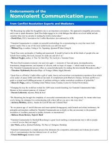
A typical conflict scenario is shown in Fig. 2.1. The circle centered at aircraft B has radius Rms, which is the allowable minimum separation to avoid conflict. Aircraft B is considered stationary, while A proceeds along the relative velocity vector. To avoid conflict, the relative 1
05/31/07
velocity vector must be directed along or outside the dashed lines tangent to the circle (conflict zone). If the allowable minimum separation to avoid conflict is Rms (currently 5 nmi outside terminal airspace), then the required angle between vR and s0 is seen to be ! = ± sin -1 (R ms /S0 )
(2.3)
where S0 is the length of the LoS vector. Note that when S0 ≤ Rms, the aircraft are already in violation: it is clear that a potential conflict must be detected while |β| < 90° in order to effect a resolution. (Angles shown as increasing cw are positive.) The situation shown in Fig. 2.1 indicates that a conflict exists, that is, the dashed line containing the relative velocity vector vR penetrates the conflict circle of radius Rms (at point F). Horizontal resolution is achieved when one or both aircraft maneuver to cause vR to rotate about point A by an angle µ = ! " # , so that the relative velocity vector lies along either tangent line. It is clear from Fig. 2.1 that a rotation of the velocity triangle ACP to either line will resolve the conflict, and can always be accomplished by each aircraft turning by the same angle. For operational reasons, however, single-aircraft maneuvers are preferred and will be considered here. C D vA
vB vR
P
β
E
F Rms
α
s0
A
B
β vA vB
Fig. 2.1 Position and velocity geometry for a level conflict scenario. Clearly, no aircraft can turn instantaneously. However for conflicts detected early enough (at least four minutes before minimum separation), turn dynamics should not be a concern. Note however, that a turn in a significant wind field will of course affect the ground speed of the turning aircraft, so that any resolution will require iteration, with a possible change in the airspeed of that aircraft. Winds are considered negligible in what follows. III Conflict Parameters In order to describe the conflict scenario of Fig. 2.1 quantitatively, the magnitude and heading of vectors s0 and vR must be computed. In a Cartesian coordinate system with the x-axis pointing North and the y-axis pointing East, the quantities for the LoS vector are given by S0 = [(!x)2 + (!y)2 ]1/2 ; " 0 = tan #1 (!y / !x)
(3.1) 2
05/31/07
where Δx = xB – xA and Δy = yB – yA. Note that heading angles are measured positive cw from the vertical (North) on the page. To compute the relative velocity vector, first assign heading angles ψA, ψB and speeds VA, VB to the velocity vectors vA and vB, respectively. To obtain the speed VR and heading ψR of the relative-velocity vector, apply the Law of Sines to the velocity triangle ACP in Fig. 2.1 VA / sin(! B " ! R ) = VB / sin(! A " ! R )
(3.2)
and use trigonometric identities to obtain ! R = tan "1 (N / D); VR = (N 2 + D 2 )1/2 where N = VA sin ! A " VB sin ! B; D = VA cos ! A " VB cos ! B .
(3.3)
If the aircraft do not maneuver to avoid the conflict, their minimum separation will occur at point E (the line segments AE and DB are perpendicular). Minimum separation is represented by the segment BE . Its length and the predicted time to reach point E will be given by
rms = S0 sin !; t ms = S0 cos! / VR
(3.4)
where S0 is the initial separation at the time of conflict prediction and VR is the relative speed. An important parameter for representing a conflict is the predicted time to reach first-loss-ofseparation (point F in Fig. 2.1). The distance to first loss along the relative velocity vector is the difference AE ! FE , which is equivalent to 2 1/2 d fl = S0 cos! " (R 2m " rms )
(3.5)
Recall that S0 is the line-of-sight distance between aircraft A and B. Hence, the predicted time to reach first loss of separation is
t fl = d fl / VR
(3.6)
The conflict data generally include the position coordinates and velocities at the predicted firstloss points for each aircraft. Occasionally, one or both aircraft may be turning during the interval between t0, the initial time and tfl, the predicted first-loss time. As most turning algorithms assume constant velocity, it may be helpful to compensate for any turns by calculating the vector between points to reset the headings ψA and ψB. It should be noted that the predicted time to reach first loss can then also be calculated from
t fl = d A / VA or t fl = d B / VB
(3.7)
where dA and dB are the distances between the initial and first-loss points. Useful parameters for specifying a turn maneuver are the time and distance the aircraft must fly along the vector leg to reach a suitable turn-back point (shown as point D in Fig. 2.1). At this point, the maneuvering aircraft may turn back toward its original track and proceed to a downstream waypoint. The turn-back point is defined so that a heading change of the relative velocity vector of no more than -2µ will avoid re-entering the conflict zone. Since the line segments AE and DB are perpendicular, it is easy to show that the distance between points A and D is given by
3
05/31/07
d tb = S0 (cos! + sin! tan µ) = S0 cos" / cosµ
(3.8)
The time and actual distance required for the aircraft to reach turn back are t tb = d tb / VR* ; d2tb = VA t tb
(3.9)
* R
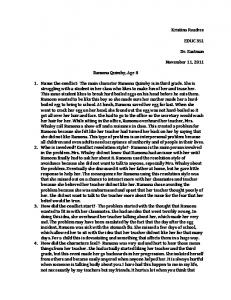
where V is the speed of the resolved relative velocity vector along AD . IV Single Aircraft Resolution Resolution schemes that have one aircraft making a heading change have been devised [1-3]. These may be preferable to providing simultaneous advisories to both aircraft in conflict. Refer to the expanded velocity diagram of Fig. 4.1, where the information shown in Fig. 2.1 has been simplified. This diagram makes it possible to easily visualize a resolution performed by aircraft A, either by turning ccw (vector vA rotates about point C) until the relative velocity vector lines up with the upper dashed tangent line at point c, or turning cw until the relative velocity vector lines up with the lower dashed line at point e. Notice that in this example, A is the faster aircraft: there will be one valid solution for each tangent line.
C c
vB vA
Rms
D B
A e
vA
vB
Fig. 4.1 Heading changes for aircraft A to resolve a conflict (VA > VB). The resolved heading for the faster aircraft is obtained by applying the Law of Sines to the new velocity triangle (either ACc or ACe). The result is ! *A = ! *R + sin -1[" V sin(! B # ! *R )]; " V = VB / VA
(4.1)
where ! *A is the new heading of aircraft A (either Cc or Ce ) and ! *R is the heading of the resolved relative velocity vector (either Ac or Ae ). The circle is chosen to realize a specified minimum separation (e.g. Rms = 7 nmi).
4
05/31/07
For an example of this resolution maneuver, suppose that VA = 356 kn, ψA = 133°, VB = 300 kn, ψB = –157° From Eq. 3.3 the magnitude and heading of the relative-velocity vector are VR = 379.1 kn; ψR = 85° Since the initial positions of aircraft A and B are known, the magnitude and heading for the lineof-sight vector between them can be computed by Eq. 3.1. Suppose that the LoS vector has length S0 = 22 nmi and heading ψ0 = 90°, so that α = -5°. The predicted time to first loss (penetration of the Rms = 5 circle), calculated using Eqs. 3.5 and 3.6, is tfl = 2.7 min. Solution of Eq. 2.3 to achieve a desired minimum separation of Rms = 7 nm yields a required β = ± 18.6°. Conflict resolution will be achieved by turning aircraft A: solve Eq. 4.1 for either ccw or cw rotation of the vector vA (in a negligible wind field) to obtain for µ = !13.5°: " *A = 110.5°; " *R = 71.4°; VR* = 475.3 kn; d2tb = 16.9 nmi (left turn) for µ = 23.6°: " *A = 165.7°; " *R = 108.6°; VR* = 216.3 kn; d2tb = 39.4 nmi (right turn)
Hence, aircraft A must turn left (behind aircraft B) by 22.5° or right (in front of B) by 32.7° to resolve the conflict. A “turn-in-front” usually requires a greater distance before the aircraft can turn back to resume its flight-plan route. For resolution by the slower aircraft, refer to Fig. 4.2, and again rotate vector vA about point C until the relative velocity vector lines up with either tangent line. Here it is seen that a vA rotation yields two intersections with the lower tangent line (at e1 and e2), and two intersections with the upper tangent line (at c1 and c2). In this case, there are two valid solutions for the slower aircraft with each tangent line. In some cases, however, there may be no solutions for a given tangent line. The limiting conditions are derived in Appendix A.
C vB vA
c1 A
e1
Rms
c2 D1
B e2
vA vB
Fig. 4.2 Heading changes for aircraft A to resolve a conflict (VA < VB).
5
05/31/07
When two valid solutions exist for the slower aircraft, the first is given by Eq. 4.1; the second solution will be ! *A = ! *R " sin -1[# V sin(! B " ! *R )] + $
(4.2)
Consider interchanging the aircraft labels of the previous example so that A again turns VA = 300 kn, ψA = –157°, VB = 356 kn, ψB = 133° The speed and heading of the relative-velocity vector are now VR = 379.1 kn; ψR = –95° Recall that the LoS vector has magnitude S0 = 22 nm; its heading is now ψ0 = –90° (α = –5°). The predicted time to first loss is still 2.7 min, and Rms = 7 nm again requires that β = ± 18.6°. Conflict resolution will again be achieved by turning aircraft A. However, each of the two velocity-vector rotations must be checked for validity, i.e., the ccw rotation is µ = -13.5°, while the cw rotation is µ = 23.6°. From Eq. A.3, the valid range is !9.4° < µ < 105.5° . Hence the ccw rotation yields no solution, while there will be two solutions for the cw rotation. For µ = 23.6°, the solutions are obtained from Eqs. 4.1 and 4.2 (assuming a negligible wind field) as ! *A = "100.9! ; ! *R =–71.4°; VR* = 585.4 kn; d2tb = 12.3 nmi (right turn) ! *A = 138.0! ; ! *R =–71.4°; VR* = 62.8 kn; d2tb = 114.3 nmi (left turn)
Hence, aircraft A must turn right (behind aircraft B) by 56.1° or left (in front of B) by 65° to resolve the conflict. Note that the turn in front requires a much longer vector leg. V A Practical Turn Algorithm In the previous section, the turn was dependent on the radius of the chosen conflict circle (the desired minimum separation). A more practical approach is to choose a set of turns for the maneuvering aircraft (eg. ±15°, ±30°, etc.), test for feasibility to meet some minimum separation, and order the successful turns by the predicted delay required to complete the maneuver. This approach is consistent with current operational practice. For aircraft A, with a desired turn Δψ, the target heading will be
! *A = ! A + "!
(5.1)
Next, use Eq. 3.3 to calculate the resolved velocity vector (! *R , VR* ) . The required rotation from the LoS vector and the minimum separation achieved with this turn will be ! = " *R # " 0 ; R ms = S0 sin !
(5.2)
Now, if |β| < 90° and Rms is greater than some desired minimum separation (say 7 nmi), then continue with this turn maneuver by calculating µ, the rotation of the relative velocity vector, and ttb , the predicted time to reach the turn-back point, and the distance along the vector leg to turn back, using Eqs. 3.8 and 3.9 to obtain µ = ! " #; t tb = (S0 cos# / cosµ) / VR* ; d2tb = VA* t tb
(5.3)
Finally, check that ! †R = ! *R , where ! †R = ! R + µ . If so, continue on to find a suitable return waypoint, which will be covered in the next section. 6
05/31/07
If |β| < 90°, and the predicted Rms is less than the desired minimum separation, abandon the turn trial and try a turn in the opposite direction (or go to the next larger turn, if possible). However, if |β| ≥ 90° the algorithm is not valid, although a vector turn still may result in a resolution of the conflict. In this case, choose t tb = 2d fl / VA* , where dfl is the distance to first loss for aircraft A. Let’s return to the first example of section IV, and consider a turn for aircraft A that yields a minimum separation of at least 7 nmi. For a left turn of 25°, the target heading will be ! *A = 133 " 25 = 108 °. The resulting velocity vector, minimum separation, and turn-back distance will be ! *R = 70°; VR* = 485.1 kn; R ms = 7.5 nmi; d2tb = 16.6 nmi
The check of Eq. 5.3 verifies that the velocity vector has, in fact, been rotated ccw by µ = 15° to provide a resolution with predicted minimum separation of 7.5 nmi. The results of the second example of section IV imply that selection of a cw turn from the set (15°, 30°, 45°, 60°) would be limited to 60°: the other right turns would yield predicted minimum separations less than 7 nmi. For a right turn of 60°, the target heading will be ! *A = "97°, and the resulting velocity vector, minimum separation, and turn-back distance are ! *R = "69.7°; VR* = 595 kn; R ms = 7.6 nmi; d2tb = 12.2 nmi
VI Return to Flight-Plan Route To complete a turn maneuver, the aircraft must return to its original flight path, preferably to a designated flight-plan waypoint. Selection of candidate return waypoints is made by specifying a suitable “window” such that the range R1 from the initial point to the waypoint is
R min < R1 < R max
(6.1)
where the minimum range is set to twice the distance to first loss. This distance is usually available in the conflict data record; it can also be estimated using Eq. 3.5. The maximum range is set to the lesser of the range to the final fix and 1000 nmi. The final fix is generally excluded from return candidacy. If no flight-plan waypoint exists within the range window, then one or more waypoints may be inserted and the one ultimately selected added to the flight-plan set. A typical level conflict resolution maneuver for a cw turn is shown in the plan view of Fig. 6.1. B
First-loss points
d2wp
Flight-plan route ϕ2tb
A
d2tb Turn-back point
Fig. 6.1 Typical level conflict resolution plan view.
7
Return waypoint
05/31/07
A return waypoint is selected by testing each candidate to satisfy the conditions
d2wp > d2tb and !2tb < 90°
(6.2)
where d2wp is the distance to the return waypoint from the turn-back point, d2tb is the distance from the initial point to turn back, and ϕ2tb is the turn angle between the vector leg and the return leg of the maneuver. This test is based on operational considerations. Note that if the test fails for the last waypoint candidate, the value of d2tb can be reduced until the test is satisfied. VII A Case Study The level turn algorithm described in sections V and VI was developed and tested in a MATLAB environment, converted to JAVA and implemented with the AAC auto-resolution software in the ACES air-traffic simulation [5]. For the tests being conducted at Ames Research Center, the simulation uses flight-plan data from one day of flights in the Cleveland airspace. The aircraft start from airports in the USA at scheduled departure times, and fly according to their filed flight plans. Each aircraft within the Cleveland Center is checked for conflict with all other aircraft in the Center every two minutes, and a conflict list is sent to the AAC autoresolution module. The ACES–AAC interface is shown in Fig. 7.1. ACES Create trajectories from flight plans Check trajectories for conflicts
AAC Module ACES conflict list
AAC trial plans Check trial plans for feasibility, conflicts
Implement successful trial plans
Trial-plan status
Accept trial plans
Create a “trial-plan” resolution for each predicted conflict
Iterate trial plan when necessary Choose plans to be implemented
Fig. 7.1 Interface of ACES and the AAC auto-resolution module. This section provides a case study of one level conflict pair for which several trial plans are created. The trial plans consist of level turn maneuvers for either aircraft, which would be created in the AAC module, and ordered so that the maneuver with the least delay from the original route would be sent to ACES to be checked for feasibility and conflicts. This study, however, was performed with MATLAB using the level resolution algorithms described in the previous sections, applied to ACES conflict data. The same algorithms, with some practical constraints, have been implemented in the AAC module. The case chosen for this paper is a conflict between flights AAL309 (an MD-80) and UAL8193 (a B757), flying at 31000 ft through the Cleveland Center, both en route to Chicago. The data 8
05/31/07
record accompanying each conflict detected by ACES and sent to the AAC module includes, for each aircraft, position, velocity, and time at the initial point, the first-loss point, the minimum separation point, and each flight-plan waypoint. Data for the initial point should be considered “measured”, the rest, “predicted” by the ACES trajectory generator. A summary of the conflict data is given in Table 7.1. Table 7.1 Conflict data for level-conflict case study
AAL UAL
Alt, ft 31,000 31000
Initial T0 = 0 Spd, kn Hdg, deg 438.8 -107.0 483.5 -106.9
First Loss TFL = 5.5 min Alt, ft Spd, kn Hdg, deg 31000 439.0 -106.7 31000 485.0 -106.9
Min Sep TMS = 6.3 min Alt, ft Spd, kn Hdg, deg 31000 439.0 -105.7 31000 485.0 -106.9
Calculations of line-of-sight and relative velocity vectors, alpha, and prediction of minimum separation (from section III) yield
S0 = 9.1 nmi, ! 0 = 72.4°; VR = 44.7 kn, ! R = 71.0°; " = -1.4°; R ms = 0.2 nmi Examination of the data reveals that the aircraft have all flight-plan waypoints in common, i.e., they are “in trail”, only 9.1 nmi apart at the initial point. The speeds differ by about 45 kn, and the UAL flight is predicted to overtake the AAL flight in 6.3 min (Rms = 0.2 nmi) if no action is taken. Trial turn resolutions of ±15° and ±30° will be attempted for each aircraft: a turn of AAL will allow the faster UAL to be ahead when it passes the AAL return waypoint; however, a UAL turn may not allow the faster aircraft to be ahead when it returns to its route. Turning the slower AAL aircraft would probably be the first choice of an ATC Controller. The trial-turn results are shown in Table 7.2. Table 7.2 Summary of turn maneuvers (Rms at least 7 nmi) a/c
Turn
Rms (pred)
Rms (test)
d2tb, nmi
ϕ2wp
d2wp, nmi
Delay, min
wpt
A A L
–15° +15° –30° +30°
8.1 8.0 8.3 8.2
8.0 8.0 8.3 8.2
72.0 63.0 41.8 36.1
34.8° -23.8° 50.8° -45.4°
74.3 69.7 61.7 64.6
0.9 0.3 1.4 1.0
7 6 3 3
U A L
–15° +15° –30° +30°
8.9 8.9 * *
8.8 8.9 9.1 9.1
78.4 76.6 89.0 89.0
33.3° -24.1° 62.4° -53.2°
86.4 84.0 96.1 90.7
0.9 0.4 3.4 2.2
8 8 8 8
* |β| > 90°: vector turn (algorithm not useful) It should be noted that the MATLAB resolution software includes a level conflict check. The inter-waypoint paths are tested for separation every 5 sec for each trial plan, with a look-ahead time of 12 min. Although no turn dynamics are modeled, this check is useful for monitoring resolution performance. In the column labeled “Rms (test)” it is seen that all turns appear to meet the requirement that Rms ≥ 7 nmi. For the ±30° turns of the faster UAL aircraft, however, the calculation of Eq. 5.2 requires that |β| > 90°. Hence the algorithm predictions are no longer
9
05/31/07
valid. For both these turns, however, the vector maneuver is conflict free, at least for the first 12 min. For all other turns, the minimum separation predicted by the algorithm compares closely with the test.
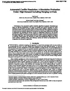
Fig. 7.2 A cw turn resolution of 15° for the slower AAL aircraft. The turn of 15° for the AAL aircraft, shown in the plan view of Fig. 7.2, allows the faster UAL aircraft to pass in front and results in the least delay (0.3 min). In the ACES-AAC implementation, this maneuver would be tried first. The next smallest delay (0.4 min) is for the turn of 15° for the UAL aircraft. While the vector leg of this maneuver is conflict free, “stretching” the path of the faster aircraft may cause a problem near the return waypoint if both aircraft are still at cruise altitude. The largest delay (3.4 min) is required for the 30° vector turn of the faster UAL aircraft: again the aircraft will likely be in conflict near the return waypoint. Observe that both UAL vector turns require a longer path before returning to the flight plan (at the last candidate return waypoint). IX Concluding Remarks This short paper has documented a simple and reliable level turn resolution which has been included with a suite of automated resolutions in an advanced air-traffic simulation. The longterm goal of this work is to extend the Automated Airspace Concept to the real-time CenterTRACON Automation System [6]. The present paper outlines the level-turn algorithm, and includes a procedure to turn back to a waypoint and resume the original flight plan. The measure 10
05/31/07
for comparing level turns is based on minimizing the delay required for an aircraft to complete its maneuver. References [1] Bilimoria, K.D.: A Geometric Optimization Approach to Aircraft Conflict Resolution, AIAA 2000-4265, AIAA Guidance, Navigation, and Control Conference, Denver, CO, Aug 14-17, 2000. [2] Paielli, R.A.: Algorithms for Tactical and Strategic Conflict Resolution, AIAA 2001-7910, AIAA Technology, Integration, and Operations Forum, Los Angeles, CA, Oct. 16-18, 2001. [3] Yutaka, F., Erzberger, H.: Strategic Conflict Resolution Methods of Aircraft, Electronic Navigation Research Institute (ENRI), Japan, Paper No. 90, January 1998. [4] Airspace Concept Evaluation System (ACES), described at the NASA Ames website: www.vams.arc.nasa.gov/activities/ACES.html [5] Erzberger, H. Automated Conflict Resolution For Air Traffic Control, 25th International Congress of the Aeronautical Sciences, September 2006. [6] Center-TRACON Automation System (CTAS), described at the NASA Ames website: www.CTAS.arc.nasa.gov Appendix A This Appendix reviews the conditions for a single-aircraft heading resolution to resolve a horizontal conflict when aircraft A maneuvers and the speed VA is less than the speed of B (VB). In this case, it may be possible to rotate vA to obtain two intersections for a given rotation µ of the relative velocity vector; otherwise there will be no intersections. Fig. A.1 shows the limit for two solutions to occur: a cw rotation of the relative velocity vector from heading ! R by an angle µmax to a resolution heading ! *R max , and a ccw rotation by an angle µmin to a resolution heading ! *R min . ! *R min
E
C vA
vB
!R
vR
! LoS
A
! *R max
D
Fig. A.1 The limiting case for two solutions with VA < VB (A maneuvering). 11
05/31/07
Note that both resolution vectors are tangent to circle of radius VA. Simple trigonometry identifies the included angles of the right triangles CAE and CAD as
!CAE = " # [($ R + µ min ) # $ B ]; !CAD = " # [$ B # ($ R + µ max )]
(A.1)
which leads to the solutions µ min = ! B " ! R " # + sin "1 (VA / VB ); µ max = ! B " ! R + # " sin "1 (VA / VB )
(A.2)
Hence, for two solutions to exist for a given rotation of the velocity vector by an angle µ,
µ min < µ < µ max
(A.3)
12