An Architecture for Authorization and Delegation in Distributed Object-Oriented Agent Systems
Pekka Nikander
DOCTORAL DISSERTATION
An Architecture for Authorization and Delegation in Distributed Object-Oriented Agent Systems Pekka Nikander Helsinki University of Technology Department of Computer Science Telecommunications Software and Multimedia Laboratory FI-02015 TKK, Espoo, Finland Author’s address: Pekka Nikander Ericsson Research FI-02420 JORVAS Finland
[email protected]
Copyright © 1999 Pekka Nikander All rights reserved.
ISBN 952-91-0786-2
Dissertation for the degree of Doctor in Technology to be presented with due permission for public examination and debate in Auditorium T2 at Department of Computer Science, Helsinki University of Technology (Espoo, Finland) on Friday, 19th of March, 1999, at 12 o’clock noon.
To my newborn daughter
Abstract Public key infrastructures and authentication protocols, in the sense they are currently known, have been publicly studied since 1978 [23]. In this work I demonstrate how I, together with the research group I have had the privilege to direct, have further developed these concepts in the Object-Oriented field. In our research, we have implemented a public key based system that allows distributed agents to securely co-operate in an insecure network. In this thesis, I focus on the following four interrelated aspects. First, I define a concrete secure software architecture for distributed software agents. Second, I describe our implementation of an Object-Oriented protocol framework for cryptographic protocols. Third, I show how an authorization based Public Key Infrastructure can be used to manage the security of Java based, Object-Oriented software Agents. And finally, I describe how this infrastructure can be extended to support distributed, secure agent execution and permission delegation. In the work as a whole, my goal has been an open, extensible security architecture that allows distributed software agents to co-operate securely. In this context, security1 mainly means two things. First, the agents must be able to trust in the underlying computing machinery, and also trust in each other. Second, the agents must be able to delegate rights among themselves, and to create secure connections between any two communicating agents. The distributed secure software architecture can be considered a high level framework where the protocol framework and the Public Key Infrastructure (PKI) plug in. It defines the security related subsystems for typical Object-Oriented execution environments, focusing on distribution and thereby cryptographic means of implementing security. The Object-Oriented protocol framework provides a supportive base, on top of which various cryptographic protocols can be built. In this sense, cryptographic protocols include both session encryption protocols used to protect actual data traffic between communicating parties and key management and authentication protocols, used to create secure channels used for the actual data transfer. The Public Key Infrastructure (PKI) is needed to provide sufficient trust relationships and an initial security context to the communicating parties so that the authentication and key management protocols can be operated. In this work, my sole focus has been on an authorization based (as opposed to identity based) PKI. In practical terms, this means that the secure channels created within such an authorization framework automatically get strong relationship semantics, providing the communicating parties explicit information about the level and form of trust mediated. Finally, the architecture with its protocol and PKI components makes it possible to create Object-Oriented software agents, distribute them into the network, and let them collaborate in a secure way. In our system, agents are represented as collections (JAR packages) of Java classes. The agent code may be loaded into a trusted Java Virtual Machine, where it is run. The running agents are able to create and evaluate trust relationships between each other, allowing dynamic delegation and creation of secure communication channels. 1
Security per se is, naturally, a much larger concept. However, for the purposes of this study, I have concentrated on these two aspects of security in defining the presented security architecture.
ii
Nikander
Acknowledgements This dissertation is a result of a few years of development in the Telecommunications Software and Multimedia laboratory at Helsinki University of Technology. During this time, I have had a privilege of supervising the M.Sc. work of several bright students, as well as working with a number of other undergraduate and graduate students. Therefore, I want to thank Timo P. Aalto, Tero Hasu, Esko Heimonen, Ursula Holmström, Kaj Höglund, Yki Kortesniemi, Ilari Lehti, Jonna Partanen, Juha Pärssinen, Bengt Sahlin, Mikael Suokas, and Sanna Suoranta for indirectly contributing to my thinking and thereby this thesis. I am especially grateful to Ilari, Jonna, Juha, and Yki for their contributions to the publications that form a part of this thesis, and for taking care of most of the practicalities involved with submitting the papers for publication. Until May 1998, while conducting research towards this thesis, I also acted as the Chairman of the Board at Nixu, a small consultancy company I had founded in 1988. I want to thank all of my colleagues at Nixu for their patience and understanding — simultaneously conducting academic research and acting in a managerial position in a consultancy company was not always easy. In Nixu, my special thanks go to Lea Viljanen, with whom I had a privilege to write one of the included publications, and Jukka Kotkanen and Oiva Karppinen, who made my work easier by taking care of a number of issues at Nixu. From August 1998, I have acted as a Research Manager at Ericsson research. I thank Ericsson for the financial support for publishing and defending this thesis, my managers Kristian Toivo and Rolf Svanbäck for their support and encouragement, and my colleagues at Ericsson Telecom Research & Development for their understanding and support. For initial inspiration, I am grateful to Major Risto Silvasti and senior systems specialist Erkki Suominen, who during my military service at Defence Forces Computing Centre suggested that I would pursue further academic studies in the area of computer security. This resulted in my Licentiate’s thesis, and thereby contributed to the birth of this dissertation. My special thanks go to my friends and colleagues Tuomas Aura, Petteri Koponen, Juhana Räsänen, and Jorma Wall for reading through the manuscript of this thesis, and for pointing out a number of mistakes. I thank my preliminary examiners Dr. Arjen Lenstra and Professor Erland Johnson for their effort and for their invaluable suggestions for enhancements, and my opponent Dr. Thomas Berson for travelling to Finland to examine and debate my views. To my supervisor and personal friend, Professor Arto Karila, I am especially in dept. He taught me patience, had time for me at inconvenient moments, taught how to write good papers by co-authoring the first publication included in this thesis, and especially acted as a source of hope and belief at hard times. Without his encouragement and support this thesis would be of much lesser quality. Last, I thank with all my heart my wife Kirsi Nikander for all her understanding, support and love, and our newborn daughter for being such a lovely and easy baby both before and after her birth. Helsinki, February 1999
Table of Contents
iii
Table of Contents Abstract. . . . . . . . . . . . . . . . . . . . . . . . . . . . . . . . . . . . . . . . . . . . . . . . . . i
Acknowledgements . . . . . . . . . . . . . . . . . . . . . . . . . . . . . . . . . . . . . . . .ii
Table of Contents . . . . . . . . . . . . . . . . . . . . . . . . . . . . . . . . . . . . . . . . . iii
Original Papers . . . . . . . . . . . . . . . . . . . . . . . . . . . . . . . . . . . . . . . . . . xiii
1
Introduction . . . . . . . . . . . . . . . . . . . . . . . . . . . . . . . . . . . . . . .1 1.1 1.1.1 1.1.2 1.2 1.2.1 1.3 1.3.1 1.3.2 1.3.3 1.3.4 1.3.5 1.3.6 1.4 1.4.1 1.4.2 1.5 1.5.1 1.5.2 1.5.3 1.6
Background . . . . . . . . . . . . . . . . . . . . . . . . . . . . . . . . . . . . . . .1 Organization of this Thesis . . . . . . . . . . . . . . . . . . . . . . . . . .2 Original papers . . . . . . . . . . . . . . . . . . . . . . . . . . . . . . . . . . .2 Distributed agent systems. . . . . . . . . . . . . . . . . . . . . . . . . . . . .3 Principals . . . . . . . . . . . . . . . . . . . . . . . . . . . . . . . . . . . . . . . .3 Authentication, Access Control, Authorization, and Trust . . .4 Authentication . . . . . . . . . . . . . . . . . . . . . . . . . . . . . . . . . . . .5 Authentication protocols . . . . . . . . . . . . . . . . . . . . . . . . . . . .6 Access Control. . . . . . . . . . . . . . . . . . . . . . . . . . . . . . . . . . . .7 Object-level Access Control . . . . . . . . . . . . . . . . . . . . . . . . .8 Authorization and Delegation . . . . . . . . . . . . . . . . . . . . . . .10 Trust and Security Policy . . . . . . . . . . . . . . . . . . . . . . . . . .11 Protocol frameworks . . . . . . . . . . . . . . . . . . . . . . . . . . . . . . .12 Conduits and Conduits+ Frameworks . . . . . . . . . . . . . . . . .13 Conduit Types and Protocol Graphs . . . . . . . . . . . . . . . . . .14 Communicating Distributed Object Environments . . . . . . . .15 Conceptual Model . . . . . . . . . . . . . . . . . . . . . . . . . . . . . . . .16 Distributed Java Environments . . . . . . . . . . . . . . . . . . . . . .16 Jini . . . . . . . . . . . . . . . . . . . . . . . . . . . . . . . . . . . . . . . . . . . .17 Summary . . . . . . . . . . . . . . . . . . . . . . . . . . . . . . . . . . . . . . . .17
iv
Nikander
2
An Architecture for Secure Distributed Computing. . . . . . . .19 2.1 2.1.1 2.1.2 2.1.3 2.1.4 2.2 2.2.1 2.2.2 2.2.3 2.3 2.3.1 2.4 2.4.1 2.4.2 2.4.3 2.4.4 2.4.5 2.5 2.5.1 2.6
3
Overview and Basic Concepts . . . . . . . . . . . . . . . . . . . . . . . .19 Conceptual overview. . . . . . . . . . . . . . . . . . . . . . . . . . . . . .20 Definition of architectural concepts . . . . . . . . . . . . . . . . . .21 Functional concepts. . . . . . . . . . . . . . . . . . . . . . . . . . . . . . .22 Implementation . . . . . . . . . . . . . . . . . . . . . . . . . . . . . . . . . .25 Securing connections with IPSEC . . . . . . . . . . . . . . . . . . . . .25 Basic structure . . . . . . . . . . . . . . . . . . . . . . . . . . . . . . . . . . .26 Policy and Semantics. . . . . . . . . . . . . . . . . . . . . . . . . . . . . .27 Implementation status . . . . . . . . . . . . . . . . . . . . . . . . . . . . .28 Managing Security Contexts . . . . . . . . . . . . . . . . . . . . . . . . .28 Implementation status . . . . . . . . . . . . . . . . . . . . . . . . . . . . .29 Policy and Certificates . . . . . . . . . . . . . . . . . . . . . . . . . . . . . .29 Principals redefined. . . . . . . . . . . . . . . . . . . . . . . . . . . . . . .29 SPKI Certificate Theory . . . . . . . . . . . . . . . . . . . . . . . . . . .30 Certificate Chains and Loops . . . . . . . . . . . . . . . . . . . . . . .31 Applying certificates to JDK 1.2 access control . . . . . . . . .34 Implementation status . . . . . . . . . . . . . . . . . . . . . . . . . . . . .36 Storing and Retrieving Certificates . . . . . . . . . . . . . . . . . . . .36 Implementation status . . . . . . . . . . . . . . . . . . . . . . . . . . . . .37 Summary of the Architecture . . . . . . . . . . . . . . . . . . . . . . . . .37 An Object-Oriented Framework for Security Protocols. . . . .39
3.1 Background . . . . . . . . . . . . . . . . . . . . . . . . . . . . . . . . . . . . . .39 3.2 Basic Elements . . . . . . . . . . . . . . . . . . . . . . . . . . . . . . . . . . . .39 3.2.1 Five types of Conduits. . . . . . . . . . . . . . . . . . . . . . . . . . . . .40 3.2.2 Messages and Messengers. . . . . . . . . . . . . . . . . . . . . . . . . .41 3.3 Secure Execution Environment . . . . . . . . . . . . . . . . . . . . . . .42 3.3.1 Language Level Security Features . . . . . . . . . . . . . . . . . . .43 3.3.2 Usage of JDK 1.2 Security Domains to Protect Protocol Fragments . . . . . . . . . . . . . . . . . . . . . . . . . . . . . . .43 3.3.3 Controlling the Flow of Messages. . . . . . . . . . . . . . . . . . . .44 3.4 Construction of Cryptographic Protocols. . . . . . . . . . . . . . . .44 3.4.1 Java Cryptography Architecture and Extension . . . . . . . . .45 3.4.2 Protocol Patterns . . . . . . . . . . . . . . . . . . . . . . . . . . . . . . . . .46 3.4.3 ISAKMP based Higher Level Framework . . . . . . . . . . . . .46 3.5 Implementation history and status . . . . . . . . . . . . . . . . . . . . .47 3.6 Contributions . . . . . . . . . . . . . . . . . . . . . . . . . . . . . . . . . . . . .48
Table of Contents
4
Distributed Trust and Policy Management. . . . . . . . . . . . . . .49 4.1 4.1.1 4.1.2 4.1.3 4.2 4.2.1 4.2.2 4.2.3 4.3 4.3.1 4.3.2 4.3.3 4.3.4 4.4 4.4.1 4.4.2 4.4.3 4.4.4 4.5
5
v
Introduction . . . . . . . . . . . . . . . . . . . . . . . . . . . . . . . . . . . . . .49 Distribution with Agents . . . . . . . . . . . . . . . . . . . . . . . . . . .49 Forms of Trust . . . . . . . . . . . . . . . . . . . . . . . . . . . . . . . . . . .50 Security Policy Defined. . . . . . . . . . . . . . . . . . . . . . . . . . . .51 Trust in Distributed Agent Systems . . . . . . . . . . . . . . . . . . . .52 Trust Relationships . . . . . . . . . . . . . . . . . . . . . . . . . . . . . . .52 Expressing Trust . . . . . . . . . . . . . . . . . . . . . . . . . . . . . . . . .53 Trusted Third Parties . . . . . . . . . . . . . . . . . . . . . . . . . . . . . .55 Components of Security Policy . . . . . . . . . . . . . . . . . . . . . . .56 Policy for Trusting in Third Parties. . . . . . . . . . . . . . . . . . .56 Policy for Believing in Recommendations . . . . . . . . . . . . .58 Policy for Access Control . . . . . . . . . . . . . . . . . . . . . . . . . .58 Enforcing Policy . . . . . . . . . . . . . . . . . . . . . . . . . . . . . . . . .58 Distributed Management . . . . . . . . . . . . . . . . . . . . . . . . . . . .59 Installation of Nodes . . . . . . . . . . . . . . . . . . . . . . . . . . . . . .59 Definition of Initial Policies . . . . . . . . . . . . . . . . . . . . . . . .60 Introducing new Trusted Parties . . . . . . . . . . . . . . . . . . . . .60 Revoking Trust . . . . . . . . . . . . . . . . . . . . . . . . . . . . . . . . . .61 Summary . . . . . . . . . . . . . . . . . . . . . . . . . . . . . . . . . . . . . . . .61
Conclusions . . . . . . . . . . . . . . . . . . . . . . . . . . . . . . . . . . . . . .63
Bibliography. . . . . . . . . . . . . . . . . . . . . . . . . . . . . . . . . . . . . . . . . . . . .65
vi
Nikander
Publication I A Java Beans Component Architecture for Cryptographic Protocols .71 1 2 2.1 2.2 2.3 2.4 3 3.1 3.2 3.3 3.4 3.5 3.6 4 4.1 4.2 4.3 4.4 4.5 5 6 7
Introduction . . . . . . . . . . . . . . . . . . . . . . . . . . . . . . . . . . . . . .71 The architecture . . . . . . . . . . . . . . . . . . . . . . . . . . . . . . . . . . .72 The essential components . . . . . . . . . . . . . . . . . . . . . . . . . .73 The optional components. . . . . . . . . . . . . . . . . . . . . . . . . . .73 Implementational requirements. . . . . . . . . . . . . . . . . . . . . .74 Related work . . . . . . . . . . . . . . . . . . . . . . . . . . . . . . . . . . . .75 The implementation framework . . . . . . . . . . . . . . . . . . . . . . .75 Component based software engineering . . . . . . . . . . . . . . .76 Basic Conduits architecture. . . . . . . . . . . . . . . . . . . . . . . . .77 Using Java to build protocol components . . . . . . . . . . . . . .79 Usage of language level security features . . . . . . . . . . . . . .80 Object level design patterns used in the resulting architecture . . . . . . . . . . . . . . . . . . . . . . . . . . . . . .81 Protocol design patterns. . . . . . . . . . . . . . . . . . . . . . . . . . . .83 Implementation experiences. . . . . . . . . . . . . . . . . . . . . . . . . .84 The framework . . . . . . . . . . . . . . . . . . . . . . . . . . . . . . . . . .84 IPSEC . . . . . . . . . . . . . . . . . . . . . . . . . . . . . . . . . . . . . . . . .86 ISAKMP . . . . . . . . . . . . . . . . . . . . . . . . . . . . . . . . . . . . . . .88 Non-cryptographic protocols. . . . . . . . . . . . . . . . . . . . . . . .88 Availability . . . . . . . . . . . . . . . . . . . . . . . . . . . . . . . . . . . . .88 Summary . . . . . . . . . . . . . . . . . . . . . . . . . . . . . . . . . . . . . . . .88 Future work . . . . . . . . . . . . . . . . . . . . . . . . . . . . . . . . . . . . . .89 UML class diagram . . . . . . . . . . . . . . . . . . . . . . . . . . . . . . . .93
Table of Contents
vii
Publication II A Java Beans Framework for Cryptographic Protocols. . . . . . . . . . . .95 1 1.1 1.2 1.3 2 2.1 2.2 2.3 2.4 2.5 3 3.1 3.2 3.3 4 4.1 4.2 4.3 4.4 5 5.1 5.2 6
Introduction . . . . . . . . . . . . . . . . . . . . . . . . . . . . . . . . . . . . . .95 Underlying Assumptions. . . . . . . . . . . . . . . . . . . . . . . . . . .97 Component Based Software Engineering . . . . . . . . . . . . . .97 Related Work. . . . . . . . . . . . . . . . . . . . . . . . . . . . . . . . . . . .99 The Implementation Framework . . . . . . . . . . . . . . . . . . . . . .99 Basic Conduits Architecture . . . . . . . . . . . . . . . . . . . . . . .100 Using Java to build protocol components . . . . . . . . . . . . .106 Protocol Messages. . . . . . . . . . . . . . . . . . . . . . . . . . . . . . .107 Running Protocols . . . . . . . . . . . . . . . . . . . . . . . . . . . . . . .108 Protocol design patterns. . . . . . . . . . . . . . . . . . . . . . . . . . .113 Building Protocols with Java Conduits . . . . . . . . . . . . . . . .113 Lower layer protocols vs. upper layer protocols . . . . . . . .114 Building Lower Layer Protocols . . . . . . . . . . . . . . . . . . . .114 Building Upper Layer Protocols . . . . . . . . . . . . . . . . . . . .116 Integrating Cryptography into Java Conduits. . . . . . . . . . . .117 Implementing Cryptographic Protocols. . . . . . . . . . . . . . .117 Representing Cryptographic Transformations as Conduits . . . . . . . . . . . . . . . . . . . . . . . . . . . . . . . . . . . .118 Using Java’s Language Level Security Features. . . . . . . .119 IPSEC — An Example . . . . . . . . . . . . . . . . . . . . . . . . . . .119 Summary . . . . . . . . . . . . . . . . . . . . . . . . . . . . . . . . . . . . . . .123 Design Patterns in the Framework. . . . . . . . . . . . . . . . . . .124 Availability . . . . . . . . . . . . . . . . . . . . . . . . . . . . . . . . . . . .124 Future Work . . . . . . . . . . . . . . . . . . . . . . . . . . . . . . . . . . . . .124
viii
Nikander
Publication III Certifying Trust . . . . . . . . . . . . . . . . . . . . . . . . . . . . . . . . . . . . . . . . .129 1 1.1 1.2 1.3 1.4 1.5 2 2.1 2.2 3 3.1 3.2 3.3 4 4.1 4.2 4.3 4.4 5 6
Introduction . . . . . . . . . . . . . . . . . . . . . . . . . . . . . . . . . . . . .129 Trust Models . . . . . . . . . . . . . . . . . . . . . . . . . . . . . . . . . . .130 Security Policies . . . . . . . . . . . . . . . . . . . . . . . . . . . . . . . .131 Digital Certificates. . . . . . . . . . . . . . . . . . . . . . . . . . . . . . .131 Certificate Loops . . . . . . . . . . . . . . . . . . . . . . . . . . . . . . . .132 Outline of This Paper. . . . . . . . . . . . . . . . . . . . . . . . . . . . .132 Expressing Trust With Certificates . . . . . . . . . . . . . . . . . . .132 Certifying Identity . . . . . . . . . . . . . . . . . . . . . . . . . . . . . . .132 Certifying Authorization . . . . . . . . . . . . . . . . . . . . . . . . . .135 Simple Public Key Certificate . . . . . . . . . . . . . . . . . . . . . . .137 Principals and Naming. . . . . . . . . . . . . . . . . . . . . . . . . . . .137 Certificate Format . . . . . . . . . . . . . . . . . . . . . . . . . . . . . . .137 5-tuple Reduction . . . . . . . . . . . . . . . . . . . . . . . . . . . . . . .138 Implementation. . . . . . . . . . . . . . . . . . . . . . . . . . . . . . . . . . .139 Typical Transaction. . . . . . . . . . . . . . . . . . . . . . . . . . . . . .139 Design Patterns . . . . . . . . . . . . . . . . . . . . . . . . . . . . . . . . .140 Policy Manager Implementation . . . . . . . . . . . . . . . . . . . .141 SPKI Implementation . . . . . . . . . . . . . . . . . . . . . . . . . . . .142 Future Directions . . . . . . . . . . . . . . . . . . . . . . . . . . . . . . . . .142 Conclusions . . . . . . . . . . . . . . . . . . . . . . . . . . . . . . . . . . . . .143
Table of Contents
ix
Publication IV Storing and Retrieving Internet Certificates. . . . . . . . . . . . . . . . . . . .147 1 2 2.1 2.2 2.3 3 3.1 3.2 3.3 4 4.1 4.2 4.3 5 5.1 5.2 6
Introduction . . . . . . . . . . . . . . . . . . . . . . . . . . . . . . . . . . . . .147 SPKI . . . . . . . . . . . . . . . . . . . . . . . . . . . . . . . . . . . . . . . . . . .148 Certificate Format and Semantics . . . . . . . . . . . . . . . . . . .148 Certificate Types . . . . . . . . . . . . . . . . . . . . . . . . . . . . . . . .150 Certificate Loops . . . . . . . . . . . . . . . . . . . . . . . . . . . . . . . .151 The Domain Name System. . . . . . . . . . . . . . . . . . . . . . . . . .153 Overview . . . . . . . . . . . . . . . . . . . . . . . . . . . . . . . . . . . . . .153 Naming Non-Host Entities . . . . . . . . . . . . . . . . . . . . . . . .153 The Certificate Resource Record Type . . . . . . . . . . . . . . .154 DNS as the SPKI Certificate Storage. . . . . . . . . . . . . . . . . .155 Storing SPKI Certificates into the DNS Nodes. . . . . . . . .155 Search algorithm . . . . . . . . . . . . . . . . . . . . . . . . . . . . . . . .157 Administering certificates . . . . . . . . . . . . . . . . . . . . . . . . .159 Example . . . . . . . . . . . . . . . . . . . . . . . . . . . . . . . . . . . . . . . .160 Granting Access. . . . . . . . . . . . . . . . . . . . . . . . . . . . . . . . .161 Accessing the Service . . . . . . . . . . . . . . . . . . . . . . . . . . . .161 Conclusions . . . . . . . . . . . . . . . . . . . . . . . . . . . . . . . . . . . . .162
x
Nikander
Publication V Distributed Policy Management for JDK 1.2. . . . . . . . . . . . . . . . . . .165 1 1.1 2 2.1 2.2 2.3 2.4 2.5 3 3.1 3.2 3.3 3.4 4 4.1 4.2 5 5.1 6 7
Introduction . . . . . . . . . . . . . . . . . . . . . . . . . . . . . . . . . . . . .166 Authorization certificates . . . . . . . . . . . . . . . . . . . . . . . . .167 Basic security architecture in JDK 1.2 . . . . . . . . . . . . . . . . .168 Permissions . . . . . . . . . . . . . . . . . . . . . . . . . . . . . . . . . . . .168 ProtectionDomains . . . . . . . . . . . . . . . . . . . . . . . . . . . . . .169 AccessController . . . . . . . . . . . . . . . . . . . . . . . . . . . . . . . .169 Policy. . . . . . . . . . . . . . . . . . . . . . . . . . . . . . . . . . . . . . . . .170 Keys, certificates and certificate management . . . . . . . . .171 Shortcomings and remedies . . . . . . . . . . . . . . . . . . . . . . . . .171 Alternatives to local configuration . . . . . . . . . . . . . . . . . .172 Protection domains . . . . . . . . . . . . . . . . . . . . . . . . . . . . . .173 Scalability . . . . . . . . . . . . . . . . . . . . . . . . . . . . . . . . . . . . .174 Pseudostatic vs. dynamic permissions. . . . . . . . . . . . . . . .174 Assigning Java permissions with SPKI certificates . . . . . . .174 Policy manager . . . . . . . . . . . . . . . . . . . . . . . . . . . . . . . . .175 Dynamic policy . . . . . . . . . . . . . . . . . . . . . . . . . . . . . . . . .176 Implementation. . . . . . . . . . . . . . . . . . . . . . . . . . . . . . . . . . .177 Performance measurements. . . . . . . . . . . . . . . . . . . . . . . .178 Creating distributed protection domains . . . . . . . . . . . . . . .179 Conclusions . . . . . . . . . . . . . . . . . . . . . . . . . . . . . . . . . . . . .181
Table of Contents
xi
Publication VI Preserving Privacy in Distributed Delegation with Fast Certificates.185 1 2 2.1 2.2 2.3 2.4 2.5 3 3.1 3.2 4 4.1 4.2 5 5.1 5.2 5.3 5.4 6 7 7
Introduction . . . . . . . . . . . . . . . . . . . . . . . . . . . . . . . . . . . . .186 Authorisation and Delegation. . . . . . . . . . . . . . . . . . . . . . . .187 Trust and Security Policy . . . . . . . . . . . . . . . . . . . . . . . . .187 Certificates, Certificate Chains, and Certificate Loops. . .188 Authorisation and Anonymity . . . . . . . . . . . . . . . . . . . . .188 SPKI Certificates. . . . . . . . . . . . . . . . . . . . . . . . . . . . . . . .189 Access control revisited. . . . . . . . . . . . . . . . . . . . . . . . . . .190 An SPKI based Dynamic Security Architecture for JDK 1.2. . . . . . . . . . . . . . . . . . . . . . . . . . . . . . . . . . . . . .190 Access Control in JDK 1.2 . . . . . . . . . . . . . . . . . . . . . . . .191 Policy Management. . . . . . . . . . . . . . . . . . . . . . . . . . . . . .191 Adding Elliptic Curve based Certificates to Java. . . . . . . . .192 The Java Cryptography Architecture. . . . . . . . . . . . . . . . .193 Implementing an Elliptic Curve Cryptography Provider in Java 1.2 . . . . . . . . . . . . . . . . . . . . . . . . . . . . . .193 Extending Java Protection Domains into Distributed Agents . . . . . . . . . . . . . . . . . . . . . . . . . . . . . . . .194 Trust requirements. . . . . . . . . . . . . . . . . . . . . . . . . . . . . . .195 Expressing the Trust Requirements with SPKI Certificates. . . . . . . . . . . . . . . . . . . . . . . . . . . . . . . .196 Runtime Behaviour . . . . . . . . . . . . . . . . . . . . . . . . . . . . . .197 Preserving privacy. . . . . . . . . . . . . . . . . . . . . . . . . . . . . . .199 Implementing the architecture . . . . . . . . . . . . . . . . . . . . . . .199 Conclusions . . . . . . . . . . . . . . . . . . . . . . . . . . . . . . . . . . . . .200 References . . . . . . . . . . . . . . . . . . . . . . . . . . . . . . . . . . . . . .200
xii
Nikander
Publication VII Authorization in Agent Systems: Theory and Practice . . . . . . . . . . .203 1 2 2.1 2.2 2.3 3 3.1 4 4.1 4.2 4.3 4.4 4.5 4.6 4.7 5 5.1 5.2 5.3 6 6.1 6.2 6.3 7 8
Introduction . . . . . . . . . . . . . . . . . . . . . . . . . . . . . . . . . . . . .203 Entities . . . . . . . . . . . . . . . . . . . . . . . . . . . . . . . . . . . . . . . . .205 Principals . . . . . . . . . . . . . . . . . . . . . . . . . . . . . . . . . . . . . .205 Names and Thresholds. . . . . . . . . . . . . . . . . . . . . . . . . . . .206 Objects and Actions. . . . . . . . . . . . . . . . . . . . . . . . . . . . . .206 Forms of Trust . . . . . . . . . . . . . . . . . . . . . . . . . . . . . . . . . . .206 Direct and Delegated Trust . . . . . . . . . . . . . . . . . . . . . . . .207 Theory . . . . . . . . . . . . . . . . . . . . . . . . . . . . . . . . . . . . . . . . .208 Basics. . . . . . . . . . . . . . . . . . . . . . . . . . . . . . . . . . . . . . . . .208 Statements and expressions . . . . . . . . . . . . . . . . . . . . . . . .208 Axioms. . . . . . . . . . . . . . . . . . . . . . . . . . . . . . . . . . . . . . . .209 Distributed modalities . . . . . . . . . . . . . . . . . . . . . . . . . . . .211 Direct delegation . . . . . . . . . . . . . . . . . . . . . . . . . . . . . . . .212 Indirect Delegation of Access Rights . . . . . . . . . . . . . . . .214 Executing via a Proxy Agent. . . . . . . . . . . . . . . . . . . . . . .215 Practice. . . . . . . . . . . . . . . . . . . . . . . . . . . . . . . . . . . . . . . . .218 Generalized delegation . . . . . . . . . . . . . . . . . . . . . . . . . . .219 Looping Trust . . . . . . . . . . . . . . . . . . . . . . . . . . . . . . . . . .219 Exemplifying Policy . . . . . . . . . . . . . . . . . . . . . . . . . . . . .222 Access Control Models . . . . . . . . . . . . . . . . . . . . . . . . . . . .222 Discretionary Access Control . . . . . . . . . . . . . . . . . . . . . .222 Mandatory Access Control . . . . . . . . . . . . . . . . . . . . . . . .223 Role Based Access Control . . . . . . . . . . . . . . . . . . . . . . . .223 Implementation status. . . . . . . . . . . . . . . . . . . . . . . . . . . . . .224 Summary and Conclusions. . . . . . . . . . . . . . . . . . . . . . . . . .224
Original Papers This thesis describes the development of a new security architecture for distributed computing and especially for distributed agent based computing. The results have been or are to be published in the following seven publications. The roman numerals are used when the publications are referred to in the text. I Pekka Nikander and Arto Karila, “A Java Beans Component Architecture for Cryptographic Protocols,” in Proceedings of the 7th USENIX Security Symposium, San Antonio, Texas, Usenix Association, 26-29 January 1998. II Pekka Nikander and Juha Pärssinen, “A Java Beans Framework for Cryptographic Protocols,” to appear as Chapter 24 in Mohammed Fayad, Douglas Schmidt and Ralph Johnson (Editors), Object Oriented Application Frameworks, Volume II, Wiley, 1999. III Ilari Lehti and Pekka Nikander, “Certifying Trust,” in Imai and Zheng (Editors), Public Key Cryptography — First International Workshop on the Practice and Theory in Public Key Cryptography PKC’98, Pasifico Yokohama, Japan, February 1998, LNCS 1431, pp. 83–98, Springer-Verlag, March 1998. IV Pekka Nikander and Lea Viljanen, “Storing and Retrieving Internet Certificates,” in Knapskog, Brekne (Editors), in Proceedings of NordSec -98 — The Third Nordic Workshop on Secure IT Systems, Trondheim, Norway, 5–6 November, 1998. V Pekka Nikander and Jonna Partanen, “Distributed Policy management for JDK 1.2,” in Proceedings of the1999 Network and Distributed Systems Security Symposium, San Diego, CA, 4–6 February 1999, pp. 91–102, Internet Society, February 1999. VI Pekka Nikander, Yki Kortesniemi and Jonna Partanen, “Preserving Privacy in Distributed Delegation with Fast Certificates,” in Imai, Zheng (Editors), Public Key Cryptography — Second International Workshop on Practice and Theory in Public Key Cryptography, PKC’99, Kamakura, Kanagawa, Japan, 1–3 March 1999, LNCS, Springer-Verlag, March 1999. VII Pekka Nikander, Authorization in Agent Systems: Theory and Practice, Technical Report, 1/99 in Series A, Telecommunications Software and Multimedia Laboratory, Helsinki University of Technology, ISBN 951-22-4464-0, ISSN 1455-9722, February 1999. A revised version of this paper has been submitted to Computer Security Foundations Workshop 1999. The theme of the study was suggested by Pekka Nikander. The resulting architecture was designed by Pekka Nikander, and most of the research was conducted by Pekka Nikander, together with a group of master’s students and other undegraduates. At various times, the following students worked in the group: Timo P. Aalto, Tero Hasu, Esko Heimonen, Ursula Holmström, Kaj Höglund, Yki Kortesniemi, Ilari Lehti, Jonna Partanen, Juha Pärssinen, Bengt Sahlin, Mikael Suokas, and Sanna Suoranta.
xiv
Nikander
Chapter 1
Introduction 1.1
Background
In this thesis, I present a concrete distributed software architecture whose origin can be traced back to 1993, when I for the first time realized the problems involved in delegating access permissions and modelling trust in a distributed system. Since then, a lot has happened in the international research community. The proliferation of the Internet has raised security awareness in most organizations. Firewalls are commonplace, and a still small but rapidly growing fraction of the Internet traffic is cryptographically protected. On the other hand, the wide acceptance of the Java computing platform and the Java Beans component architecture is finally making it feasible to build large scale agent systems. Thus, to a large extent the architecture presented builds onto this international development, combining existing bits and pieces in a novel way, and creating something new in the process. Major parts of the system consist of adaptations of standard Internet protocols and services. My main contributions are visible in the following three areas where the pieces are combined in a new way, or totally new solutions are proposed. • •
•
First, I have defined a security architecture for distributed agent systems, which itself represents new insights not yet widely understood. Second, we have built a concrete Object-Oriented protocol framework — used to implement parts of the architecture — that includes a number of improvements not available in protocol frameworks before. Third, and finally, I have defined an infrastructure for distributed trust and policy management, which comprises the top layer of the architecture. Especially, its adaptation to agent computing is a piece of new development.
In practice, my PhD related work has to a large extent been an architect’s work. From the very beginning, I have had the privilege (or a pledge, depending on the point of view) of guiding a number of people working on their Master’s theses. I have channelled my architectural vision and key ideas into the problems of these Master’s theses, and worked together with each Master’s candidate in solving the finer level problems. My primary contribution is visible in the architectural level view, continuing from thesis to thesis and paper to paper. In the published papers included in this thesis, the primary ideas and solutions as well as the realization of the importance of the problem domains are solely mine. My co-authors have helped me in hammering the ideas into concrete solutions, and solving some of the finer points.
2
Nikander
1.1.1 Organization of this Thesis This Thesis consists of five Chapters and seven Publications, each publication embodying a published paper. The Publications are included separately, following the Bibliography. The Publications are numbered with roman numerals I–VII. The Chapters are organized as follows. In the rest of this Chapter, Chapter 1, I give a brief introduction to the research topic. In Chapter 2, I describe the TeSSA Telecommunications Software Security Architecture, which forms the overall software architecture for the rest of this thesis. An early version of this architecture is described in Publication I, while some finer points are described in Publications IV and V. In Chapter 3, I describe an Object-Oriented protocol development framework, named Jacob, implemented as a part of this architecture. The point of view in the chapter is an external one, focusing on how the framework functions as a tool to build other protocols. The details of the framework are described in Publication II. In Chapter 4, I illustrate how the overall architecture can be used to support distributed trust and policy management and execution in distributed agent systems. Again, focus is on the overall structure, details being explained in Publications III, VI and VII. Each chapter also describes the implementation status of our prototype, if applicable. Finally, Chapter 5 includes a summary and concluding remarks. 1.1.2 Original papers The Publications section includes reprints of selected papers that our research group has produced during the course of its research. In each paper, my personal contribution and ideas have been the driving force, creating continuity over the individual research topics. The publications are organized in rough order of detail, starting from the more general publications and working towards the more specific details. Publication I, “A Java Beans Component Architecture for Cryptographic Protocols” on page 71, draws the background. It outlines the architectural structure into which the rest of the work is based on. Next, in Publication II, “A Java Beans Framework for Cryptographic Protocols” on page 95, we describe the basement of our architecture, so to say, in detail. In Publication III, “Certifying Trust” on page 129, the focus is shifted towards the higher levels of the architecture (the “attic” vs. the basement), describing the necessary trust management elements that are needed to cover the architectural structure. Finally, the remaining publications give the missing details needed to complete the structure. Publication IV, “Storing and Retrieving Internet Certificates” on page 147, outlines an architecture for practical distributed management of trust relationships. Publication V, “Distributed Policy Management for JDK 1.2” on page 165, describes how authorization certificates can be extended to remotely manage the internal access control of Java Virtual Machines. The last two publications, Publication VI, “Preserving Privacy in Distributed Delegation with Fast Certificates” on page 185, and Publication VII, “Authorization in Agent Systems: Theory and Practice” on page 203, show how this system can be extended to cover distributed, interoperating software agents.
Chapter 1. Introduction
3
The rest of this Chapter briefly describes the necessary background, including a number of definitions. First, in Sect. 1.2, the basics of distributed systems are discussed, including definitions for the terms node, agent and principal. Then, in Sect. 1.3, the concepts of authentication, access control, authorization, and trust are defined. Sect. 1.4 gives an introduction to protocol frameworks, and, finally, Sect. 1.5, introduces communicating distributed object environments.
1.2
Distributed agent systems
For the purposes of this study, a distributed system is a computer system that consists of several nodes that are connected via an insecure network. Each node executes an operating system that is capable of running software agents and that is trusted at least to a degree. One of the features of our system is that the level of trust in the operating system is explicitly modelled in our architecture. For the purposes of the theory presented in this study, the actual nature of the nodes, links or agents is of no interest. However, the actual prototype our research group has built is based on nodes running the Java Virtual Machine (JVM) [9], networks based on standard Internet protocols, and software agents represented as packages of Java classes. Thus, in this study, the following definitions are used for nodes and agents1. Definition. A node is a computer system that runs an operating system capable of running software agents and that is connected to a network and therefore capable of communicating with other nodes through that network. Definition. A software agent is a piece of program code and data, organized as a unit, that may be loaded to a node and run. While running, it is able to perform actions in the node under the privileges that the security system has assigned to it. In purpose, these definitions are quite general and allow nodes and agents to be quite different from our prototype system. For example, nodes could well be computers running a modern operating system such as Mach or even UNIX, and the agents could be tasks under Mach or processes under UNIX. 1.2.1 Principals The users whom an information system has been created for are the natural principals in the system. They are the people that have authority, in the first place, over the data stored in the system and handled by the system. However, since people are blood and flesh rather than electrons and silicon, it is impossible for the users to be directly repre1
In the literature, software agents are often assumed to have more properties, e.g., an agent is always assumed to function as an intelligent independent unit. However, from the security point of view used in this thesis, these additional properties are irrelevant, and the simple definition is adopted. See also Sect. 4.1.1 on page 49.
4
Nikander
sented within the system. Thus, for the purpose of this thesis, we consider software programs, or agents, which execute actions on the behalf of the users, to be principals. As modern computer systems more and more perform actions initiated by themselves (according to preprogrammed schedules), it is also natural to consider the nodes and their operating systems as principals. In fact, one of the purposes an operating system exists for is to protect the underlying hardware from malicious acts. Thus, the operating system can be considered to be a principal who has the primary authority over the actual hardware and its usage. Hence, the term principal can be defined as follows. Definition. A principal is a computer node or a software agent that is (potentially) active in the system under discussion. A principal typically has authority over a number of resources. When discussion protocols, or emphasising the distinctness and remoteness of principals, the terms party and peer are often used as (rough) synonyms for principal. The term party, typically used as “protocol party”, highlights the communicative nature of a principal. The term peer, on the other hand, asserts that the principal under discussion is considered to be another similar party than the one previously discussed.
1.3
Authentication, Access Control, Authorization, and Trust
While confidentiality, integrity and availability are usually defined as the primary goals of any security system, authentication, access control and authorization are the usual means used to achieve those goals [6]. When describing security subsystems that control users’ ability to perform their activities in a computer system, these latter three terms are usually used in some combination. In this section, I describe the traditional view to authentication and access control, and start my argument why the underlying implicit assumptions behind these terms may not be the right ones for distributed systems. In Chapter 4 I return to this issue, having first gained some other background. The term authentication is usually used to denote identity authentication, as described in Sect. 1.3.1. However, the meaning of the term can be enlarged to designate any action that creates information whose origin and integrity can be verified. On the other hand, the whole applicability of the term is arguable in many occasions, as I will show. Access control, in its turn, is defined as a mechanism internal to a computer system that monitors and controls the users’, or subjects’, access to the system’s resources, or objects. The purpose of an access control system is to ensure the confidentiality, integrity, and availability of the system resources and information stored in the system. Traditional access control concepts are described in Sect. 1.3.3, while its application in Object-Oriented systems is considered in Sect. 1.3.4. Finally, authorization is usually considered to be the act of enabling a user’s access to protected data or resources. However, more often than not authorization is somehow considered to be an infrequent action that is performed by a system administrator. Furthermore, authorization is often implicitly considered to be performed by editing a lo-
Chapter 1. Introduction
5
cal security configuration database, located at or close to the protected resources. One of my major goals is to render this view old fashioned, and to replace it with a model better suited for distributed contexts. Thus, authorization, delegation, and any trust relationships involved are discussed in Sect. 1.3.5 and 1.3.6. 1.3.1 Authentication As already mentioned, in most literature the term authentication is used as a synonym for identity authentication. That it, it is used to denote that a communicating party is able to convince itself that the identity of a communication peer or the originator of a message really is the claimed one. Thus, in a “usual” authentication situation, the first party, let us call her Alice, decides to believe that she really got a message from a second party, i.e., Bob. In the case of peer authentication, she also believes that she is able to securely send messages to Bob and to securely receive more messages from Bob. However, a more thorough analysis reveals that there is a number of fundamental difficulties in this definition. First, the concept of identity is very problematic when considering a large distributed system. Second, limiting authentication to be used in connection with identity reveals to be too restricting. Third, the noun “authentication”, denoting a presumably well defined operation, appears to be ill-defined. In fact, it would be better to speak about the authenticity of some information instead of some “magic” operation that comprises the act of “authentication”1. Let us consider the problem with identity first. The term identity, stemming from Latin identidem, originally means sameness or oneness. For example, “identity” in “identity equation” denotes that both sides of an equation can be considered to indicate the same (object). Similarly, when we meet a previously unknown person for the first time, we cannot really identify that person with anything, since there is nothing that would be of the same (stuff) as that person is and that was simultaneously known to us. Thus, the usual way the term is used in the computer security literature, namely to suggest that an active communicating party carries a certain name (or identity, if you will), does not actually adhere to the original meaning of the word. In fact, it would probably be more correct to speak about re-cognition (literally, re-knowing) or even indication (of name), since the aim is to recreate an indicative relationship between the message or communication channel and an already known name or account. This is quite a different concept when compared to the literal meaning of user identification, which suggest that the computer system identifies, i.e., conceives as united, the user outside the computer and the user account inside the computer system. Taking a slightly different point of view, it has been argued that in a distributed digital system the only real “identity”, with which anything can be later related to, is a private cryptographic key [28]. That is, when we for the first time meet someone in the digital world, we may be able to learn a public cryptographic key that corresponds to the private key possessed by our new acquaintance. Later on, we can really identify a future communicating peer with a known one by being able to convince us that the new 1
As I have argued in [60], acquiring the belief that a piece of information is true, e.g., to “authenticate” a cryptographic key as belonging to a protocol party, does not necessarily require any explicit protocol act or operation, but may be a “side effect” of some other operation. See also the longer explanation on the next page.
6
Nikander
peer possesses the same private key as the old one. Thus, we may say that only cryptographic keys should be considered suitable items to function as indications of identity. Now, given these preliminaries, it becomes evident that the concept of identity authentication, as usually understood, is at least obscure if not outright wrong. Therefore, as I have already suggested in [60], it is better to enlarge the term authentication to denote the act of proving the authenticity of any object or piece of information1 instead of restricting it to denote the act of proving the authenticity of, e.g., the identity of a communicating peer or message originator, as it has been traditionally understood in the literature. Thus, we may speak about authentication of authorization, or authentication of the possession of a cryptographic key. This is the essence of point two above that suggested that limiting authentication to refer to identity is too restricting. Coming to the third point, I now show that even the concept of “authentication” itself is slightly problematic. The biggest problem is that the term, as a proper noun, suggests that there is a separate, perhaps even atomic, operation or act that is the authentication. In some sense this is true; in many occasions, we can easily point a moment of time when a specific act of authentication has not happened, and another point of time when it has been accomplished. But, this leaves the real meaning of the operation obscure, since it is usually not at all clear what happens between these two points of time, nor what is the actual result achieved. A more precise a definition is needed. Thus, to gather the essence of authentication, I first want to express its relationship to the party performing the act of authentication. Second, I want to denote that the result of authentication is a belief, possessed by the authenticating party. Third, any piece of information may be chosen by a protocol party to be considered authentic, independent on whether there has been an explicit act that has caused its authenticity to be established or not. Thus, in the scope of this work, the following definition is used. Definition. In a (distributed) computer system, by saying that a piece of information is authentic or has been authenticated, we denote that the party considering the authenticity or performing the authentication has gained enough of evidence that it is itself able to believe that the given piece of information was (once) uttered by the claimed originator, or, to be more precise, by the claimed originating principal. This definition includes the usual concept of identity authentication, when needed. However, I tend to avoid that concept due to the difficulties in defining the precise meaning of identity. Furthermore, I want to note, without pursuing more, that (in the sense given in the definition) non-repudiation may be considered to be just a stronger form of authentication instead of being a separate concept. (For more information, see [60].) 1.3.2 Authentication protocols The wide definition of the term cryptographic protocol is usually defined to denote the class of communication protocols in which cryptography is used. This large class of 1
This actually corresponds with the dictionary meaning.
Chapter 1. Introduction
7
protocols is sometimes further divided into three subclasses, which are session protocols, authentication protocols and proper cryptographic protocols. The central idea in this definition is that session protocols and authentication protocols are compositions of non-cryptographic communication protocols and “standalone” cryptography, while proper cryptographic protocols are cryptosystems where the communications is an inherent aspect of the cryptosystem itself. Examples of the latter include the DiffieHellman public key cryptosystem [23] and zero-knowledge protocols [31]. As the example of including Diffie-Hellman into the class of proper cryptographic protocols shows (as opposed to classifying it as an authentication protocol), the division is a mere convenient one rather than a fundamental one. The same aspect can be seen when considering some concrete protocols such as SSH [90] or SSL/TLS [22], which both include an authentication protocol and a session protocol combined. For this thesis, however, the distinction between session protocols and authentication protocols is an important one. On the other hand, for our purposes, making a difference between “proper” cryptographic protocols and mere composite ones is not important. Now, given these preliminaries and the definition of authentication from Sect. 1.3.1, the meaning of the term authentication protocol can now be defined. Definition. An authentication protocol is a communication protocol whose purpose is to enhance the collection of evidence available to the communicating parties so that one or more of them can believe that a given piece of information is authentic. It is a common practice to use cryptographic means in establishing new evidence. Typical belief goals include the belief that a (symmetric) cryptographic key is held by a communication peer, the belief that a cryptographic key or other random number has been generated during the protocol run, and the belief that the communication peer holds either of the former beliefs. This definition clearly includes the usual authentication protocols, including theoretical developments such as Dolev-Yao [24] and Otway-Rees [69], practical protocols like Kerberos [48] and ISAKMP [55], as well as authorization certificate systems such as PolicyMaker [18] and SDSI/SPKI [76][28][29][30]. On the other hand, the definition does not include typical session protocols, such as IPSEC [10], where the communication per se does not enhance the beliefs of the parties.1 1.3.3 Access Control Access control includes the means and methods with which the users and other active entities, such as processes and threads, are limited in their ability to manipulate objects within a computer system. The purpose of an access control system is to maintain con-
1
A session protocol may indirectly help the parties to believe in new information due to the fact that the information transferred is usually authenticated. However, this is not due to the protocol itself but due to the secure information transfer, and the (external) semantic meaning given to that information.
8
Nikander
fidentiality, integrity and availability by making it impossible (or impractically hard) for unauthorized parties to read, modify or consume information or resources. A formal definition of access control usually includes the concept of an access control matrix, which is a matrix where columns are named after subjects (active entities), rows after objects, and each cell includes the actions that the subject (given by the column) is allowed to perform to the object (identified by the row). In practice, the access control matrix is an abstract item. The information included in it is usually represented separately row-by-row, in the form of access control lists (ACL), or column-by-column, in the form of capabilities. [6] An access control list (ACL) is a security token associated with a specific object (or group of objects) that lists those subjects that may act on the object(s), and the specific actions each subject may perform on the object(s). In practice, many ACL based systems allow groups of subjects to be specified, as well as negative (denying) access control lists. A capability, on the other hand, is a security token associated with a subject that lists a number of permissions. Each permission defines one or more objects, and an action or a set of actions that the subject may perform on the object(s). [50] It is clear, from the definitions, that both ACLs and capabilities must be protected from unauthorized modification. In a way, thus, they are both themselves objects in the access control system, and the subjects’ power to modify them must be limited. This creates a chicken-and-egg problem, which is usually resolved by including a number of implicit immutable ACLs or capability modification rights in the system. For the purposes of this study, we are only interested in capabilities. Furthermore, our main interest is in explicitly signed capabilities, sometimes also called credentials, which are capabilities that are cryptographically bound to a specific subject. In the system to be presented, these signed capabilities are represented as authorization certificates [27][28]. Definition. A signed capability, or authorization certificate, is a digitally signed piece of information that assigns a subject, usually represented in the form of a cryptographic public key, one or more permissions, which allow the subject to perform specified actions on one or more specified objects in a target system. What is probably interesting in this definition is the inclusion of a target system. By including this, I want to emphasize the local nature of capabilities in a distributed system. That is, a single capability should be valid only at a specific single system, the target system, or possibly at a (small) number of interrelated systems, e.g. a clustered server, which as a group can be considered to form a single target system. As we shall see, this locality, combined with the intrinsic source of trust used in delegation, trivially solves most problems associated with the semantic meaning of permissions. 1.3.4 Object-level Access Control Let us now focus our attention on access control within an Object-Oriented system. The model we describe here is closely based on the access control system of Java De-
Chapter 1. Introduction
9
velopment Kit 1.2 [35], but the same principles could be applied to other (typesafe) Object-Oriented systems as well. However, to maintain understandability, the presentation refers to the concrete Java solutions on many occasions. In the system under discussion, one major focus here is to facilitate the co-operation of objects, possibly created and operated by several interest parties, both within a single object address space and, eventually, between distinct object address spaces. Now, before dwelling upon the actual definition and implementation of O-O access control, we must define the meaning of an (access control) subject in an O-O system. That is, there usually are no explicit processes or other active entities that can be explicitly associated with a specific subject. Rather than that, the object system includes a number of threads, each of which may execute operations on the behalf of different interest parties at a time. For example, when a thread of execution moves (during a method call) from a downloaded applet into a piece of code provided by the local runtime environment, the set of interest parties involved changes accordingly. Thus, we cannot identify the active entities, or threads, with access control subjects in the usual sense. Something else is needed. In JDK 1.2, it is the security domain concept that most closely matches with the subject of the traditional access control model. Basically, a JDK 1.2 security domain is a collection of classes (and instances of those classes) that are clumped together. For example, an Applet may consist of one or more security domains. In JDK 1.2, each security domain has a number of permissions associated with it. Thus, the JDK 1.2 security model can be seen to be a kind of a capability based model. There are a number of differences, however. First, a security domain itself is not an active entity. It is only activated when some thread of control enters some method that belongs to (a class that belongs to) that domain. Second, the active permissions that such a thread receives are usually not the full set of permissions that the particular domain has, but an intersection of permissions held by the domains that are active in the thread’s call stack. To illustrate this, let’s consider a thread that has first activated a method in class A, which has then called a method in class B, and so on up to class M. Now the method in class M attempts to access a protected resource R. In order the access to be allowed, all the security domains to which classes A, B, etc. up to M belong to, must have a permission to access the resources R. Now, when a new thread is created, the default case is to assign it those permissions that are available at the creating context. For example, if class M of our previous example were to create a new thread, the new thread would inherit, as its base permissions, the intersection of the permissions in classes A … M, i.e., the permissions available to the creating thread at the time of creation. In JDK 1.2, there is one exception to the generic rule. A security domain may have a permission to execute privileged sections. Within such a privileged session, the domain of the executing class is considered to form a virtual bottom of the execution stack. Thus, the thread of execution has those permissions that the upmost security domain has, not restricted by the permissions possessed by the other domains present in the class stack. (This functionality may be compared with the Unix set-user-id (suid) facility, which is pretty similar in spirit.)
10
Nikander
In summary, one could say that the Object-Oriented access control present in JDK 1.2 is a kind of peculiar hybrid system based on roles and capabilities. The security domains represent subjects or roles, and define permissions available through capabilities. However, the active set of permissions is not a combination of roles available at a particular moment, but an intersection of the permissions possessed by the interest parties. A more complete description of the JDK 1.2 access control system is given in Sect. 2 of Publication V. More authoritative are the paper by Gong & Schemers [35], the actual specification [36] and JDK 1.2 source code [84]. 1.3.5 Authorization and Delegation Authorization, in general, denotes sanctioning or empowering someone, i.e., to make it valid, legal, binding, or official for a person to perform certain actions in the future. Delegation, on the other hand, denotes appointing someone to act as a representative, e.g., by means of a legal proxy. This definition includes, naturally, the assumption that the delegating party actually does have the authority delegated. In the context of a (distributed) computer system, both authorization and delegation can be basically defined as acts that change the (conceptual) access control matrix. That is, when a principal is originally authorized to have access to some object, an entry is created to the access control matrix. Similarly, when a principal delegates access to some other principal, some of the first principal’s access entries are copied to the second one. In most current systems, the original authorization is usually performed by the local operating system (the node) when a process (an agent) creates a new object. However, this concept can be easily generalized so that the original authority can be considered to be assigned to the creating principal (the operating system), which immediately delegates this access to the agent (the process) that requested the creation. Seen this way, any principal, i.e. both nodes and agents, can create objects on the behalf of other objects. Among other things, this also means that the creating principal is and will be responsible for controlling the access. Definition. When a principal is created, it is implicitly authorized access to all the objects that comprise the principal. When an object (other than a principal) is created, the principal whose address space contains the object is implicitly authorized access to the object. Thus, by definition, when a computer node is installed, the principal representing the node (the operating system) is given implicit access permissions to all the physical and logical objects that comprise the node. When an agent is created, on the other hand, it is only given access to the classes and objects that are parts of that agent. In fact, these are the only implicit access rights; all other rights are delegated. Definition. A principal having a permission to control another principal or access an object may delegate, on its will, this permission to a third principal, un-
Chapter 1. Introduction
11
less explicitly prohibited. When delegating, some permissions assigned to the delegating principal are copied to the delegate. Examples of existing distributed authorization and delegation systems include the Digital Systems Security Architecture (DSSA) [34] and the Kerberos [48][59]. They are pretty similar to the system presented in this thesis in many respects. However, there are a number of differences as well. The most important differences can be summarized as follows. • First, our system explicitly models more types of trust than either DSSA or Kerberos; especially, we model types that are not related to access control but to generic security conditions that must be met. • The DSSA architecture is based on names and local access control lists, while our architecture uses signed credentials and thereby allows anonymous operation. • The Kerberos architecture is based on symmetric cryptography and centralized key distribution centres. Our architecture is based on public key cryptography and fully decentralized. Other existing prototype authorization systems that have had influence on our system include the PolicyMaker [18] and the SDSI/SPKI proposal [76][28][29][30]. Our system is based on the same (but independently developed) ideas, but goes beyond both of the proposals. 1.3.6 Trust and Security Policy All human operation involves trust. Most of this trust is so inherent to the social nature of us human beings that we seldom think about it; consequently, inability to trust is considered to be abnormal (consider, e.g., paranoia). However, most of us have explicitly decided to trust our bank to take care of our money, and have selected our physician and dentist based on the feeling that we can trust them to take care of our health problems, etc. Examples of implicit trust include the trust in that our peers, colleagues and beloved ones do not harm us and act in bona fide with respect to our aims, and that other people in our society do not put us into jail otherwise harm us without a reason. All of these examples of trust involve social or legal control to some degree. If the social control fails, or the legal system collapses, our basic security is fractured. If I had to expect someone to hit me in the street without getting caught, I could not trust the society to take care of my physical security any more. If my mother had deliberately and continuously hurt me during my infancy, I would probably have severe problems in trusting in other people at all. One of the problematic issues in wide scale distributed digital systems, such as the Internet, is the relative lack of social and legal control. For example, if I, being a Finnish citizen living in Finland, bought a computer device from an, lets say, Indonesian vendor, and the device turns out to be unreliable or faulty only after having been paid, my chances in getting retaliation are slim in the case the vendor refuses to believe me. In the same way, if some digital vendor I have never heard about stores my credit card information in their system and uses it months after the initial transaction, my chances to react (other than deny the credit statements) are relatively poor. All this implies that
12
Nikander
in a computerized system, as opposed to a physical blood, flesh, wood and iron system, trust relationships should be represented explicitly, and preferably in a way that their legal binding can be later non-repudiably proven in a court, if needed. Thus, for the purpose of this study, I want to emphasize that trust is always relative, trust is intransitive, and that trust should be made explicit. Therefore, I stick with the following definition. Definition. In the architecture under discussion, trust in a principal is a belief that the principal, when asked to perform an action, will act according to a predefined description. In particular, this belief implies the belief that the principal will not attempt to harm the requestor independently of the way it fulfils the request. Thus, trust is always expressed in relation to a principal and to an action. Furthermore, trust is not necessarily transitive [89]. Trusting someone for recommendation is different from trusting someone for direct action. This definition limits the concept of (formal) trust within the distributed system itself. It does not, however, limit us from discussing other aspects of trust when needed. Someone might even want to argue that the concept I have defined to be trust is not trust at all, since, according to them, trust is inherently human behaviour, and therefore I could not say that the computer nodes or software agents were to trust each other in any way. However, as we shall see, it is quite natural to speak about trust relationships between principals, independently on whether they are genuine presentations of trust or just dim shadows of real trust assumptions held by users and administrators. Earlier theoretical studies of trust in a distributed setting have been conducted by Raphael Yahalom and Thomas Beth [16] [89], and later, independently, by Audun Jøsang [43]. In these studies, the goal has been to develop a calculus for trust. That is, the aim has been to create a generic calculus that shows how new trust relationships may be based on existing trust relationships and recommendations. My approach is different. In the architecture described, I have made a distinction between genuine trust, trust expressions, and local security policy rules. The local security policy rules define how new (genuine or expressed) trust may be inferred based on trust expression received from other principals. This aspect is discussed in more detail in Chapter 4.
1.4
Protocol frameworks
In a distributed system, communication over the network is implemented with protocols. In the security area, as we already discussed in Sect. 1.3.2, there are various kinds of cryptographic protocols. In addition to the cryptographic protocols, also standard non-cryptographic protocols are needed in order to create fully functional secure communication systems. Usually, the protocols are stacked in a more or less layer like architecture, according to the ISO OSI or the Internet TCP/IP models. In such an architecture, a higher layer protocol uses the services provided by a lower layer protocol as primitives. Using
Chapter 1. Introduction
13
these primitives, the higher layer protocol creates new services by utilizing, for example, multiplexing, forward error correction, message reordering, message copying, security, multicasting, or other structures and functions. Experience has shown that building communication protocols, and especially cryptographic protocols, is very error-prone both in the design and implementation phases. Formal methods have been more or less successfully applied in studying protocol designs. In the implementation level, on the other hand, one of the more promising approaches seems to be the use of software frameworks. Definition. A protocol framework is a covering piece of software that facilitates implementation of communication protocols. It provides basic services needed by all communication protocols, such as multiplexing and demultiplexing, message scheduling, state machines, memory management, and encoding/decoding. Being a framework, the control of execution is managed by the scheduling service of the framework, not directly by the protocol themselves. Within such a framework, protocols are usually built in a piecewise manner. The history of protocol frameworks is relatively long. The earliest attempts include, for example, the VOPS and CVOPS protocol frameworks developed already in the beginning of 1980’s [44] [53]. More recent and popular protocol frameworks include xKernel [41], Horus/Ensemble [74][75], and Bast [33]. Of these, Horus/Ensemble is most closely related to our work, as it attempts to address security problems in addition to generic protocol development issues. However, the Horus/Ensemble security architecture is based on Kerberos and Fortezza, while our security architecture is based on the IPSEC standards and the SPKI public key infrastructure. This difference results in quite large differences in the actual architecture. Considering our work, other relations to and differences from the related work are outlined in Sect. 2.4 of Publication I on page 75. 1.4.1 Conduits and Conduits+ Frameworks The Conduits+ protocol framework, developed by Hüni, Johnson and Engel [40], has been the main source of inspiration in our frameworks related work. The relation between the Conduits+ and the Jacob frameworks is explained in Chapter 3. The Conduits framework [93] was a predecessor of the Conduits+ framework. It was built by Jonathan M. Zweig, under the direction of Ralph E. Johnson, at the University of Illinois at Urbana-Champaign around 1990/91. Between 1993 and 1995, the Conduits+ framework was developed in C++ by Hermann Hüni together with Toni Bieri and Robert Engel in Switzerland [40]. The Conduits+ framework is a fine grained framework, heavily utilizing design patterns. The design patterns, on their behalf, are proven architectural, object level, or language specific designs that have explicitly been noticed to reappear in various software projects and that propose solutions to particular sets of design problems [19]. In the Conduits+ framework, focus has largely been on object level patterns, or proper design patterns as some call them. These patterns include, for example, the Singleton,
14
Nikander
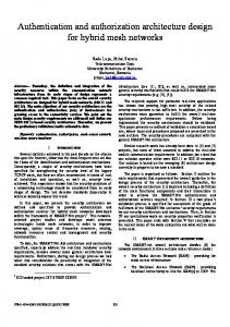
State, and Visitor patterns [32]. As we have suggested, the use of object level design patterns in protocol development results in protocol level patterns. (For an example, see Sect. 2.5 in Publication II.) 1.4.2 Conduit Types and Protocol Graphs In the Conduits+ framework, protocols are represented as protocol graphs. The graphs are built of conduits. There are the following four distinct types of conduits (Fig. 1). ...
Mux
Adaptor
Factory
Protocol
Fig. 1. The four types of conduits in the Conduits+ framework.
•
The protocol conduit type is probably the most fundamental of the conduit types. Instances of specific protocol subclasses represent run time protocols and protocol sessions. For example, a TCP state machine may be represented as a protocol. • A factory is a conduit that is able to dynamically create new conduits. For example, when a new TCP connection is created, a factory is used to create the new TCP protocol instance. • A mux multiplexes and demultiplexes messages. On multiplexing, a mux may include demultiplexing information, such as a TCP or UDP port number, to the message handled. On demultiplexing, this information is utilized in deciding where to send the message for further processing. • Finally, adaptors are used to connect the conduit graph to the outside environment. For example, there could be an Ethernet adaptor that connects a TCP/IP conduit graph to the underlying media, and a socket adaptor that provides services to traditional socket based TCP/IP applications. To create graphs, conduits are connected together through their sides. Each conduit has an A side and zero, one, or many B sides. An adaptor has zero B sides, the protocol and factory have exactly one B side, and a mux may contain many B sides. In the Conduits+ framework, the side is an abstract concept represented by distinct methods. When the connections between a number of conduits are established, the result is a protocol graph. An example of a simple protocol graph is depicted in Fig. 2, on page 15. In that example, the Factory may create new Protocols that connect to the upper side of the Mux.
Chapter 1. Introduction
Protocol
15
Protocol
Factory Mux
Protocol
Adaptor
Fig. 2. An example of a simple Conduits+ protocol graph.
1.5
Communicating Distributed Object Environments
Traditionally, distributed systems have typically been built of general purpose servers and workstations running conventional operating systems such as Unix or Windows NT. These operating systems run programs as processes or tasks. Usually, the processes are smallest functional units, being isolated from each other by means of memory protection and some kind of system call abstraction. Furthermore, the operating system provides the processes various means for inter-process communication, such as signals, semaphores, message queues, shared memory, or pipes. Some of these abstractions are also supported over the network; for example, the TCP/IP socket abstraction is one form of such a distributed inter-process communication mechanism. For a few years, there has been a number of attempts to create distributed systems that are based on smaller than process-level granularity. The remote procedure call (RPC) concept, made popular, for example, by the Sun Microsystems RPC implementation, is one established approach. Examples of early, more Object-Oriented research projects include the ACTORS [4], Linda [20] and Chorus Object Oriented Layer (COOL) [37] systems. However, only the wide acceptance of the CORBA architecture [66] and the Java runtime environment, along with the Java Remote Method Invocation (RMI) mechanism [83], are making it more common to use object-oriented concepts and object-level granularity in real world distributed systems.
16
Nikander
However, many of the research and production systems differ considerably in several respects. For example, the size of objects in a CORBA based system are typically much larger than in a pure Java system. Similarly, some systems allow object migration and location transparency while others do not. In the work presented, my focus has been on (more or less) uniform distributed object-oriented environments where the objects are, at minimum, able to request services from other objects across networks (i.e., to perform remote method calls). In an implementation of the architecture, such a distributed service request may well imply initiation of a new service component at the target system. Furthermore, if the request (or a subsequent one) transfers state from the initiating object to the responding one, migration like functionality may also be achieved. 1.5.1 Conceptual Model Since the focus of this work is on security rather than on the implementation of the object or distribution concepts, it is desirable to keep the conceptual definitions as abstract as possible. This allows one to create a security system that is applicable to a wide range of distributed systems. Definition. A Distributed Object Environment is a distributed system that supports objects and distributed inter-object communication. Since it is a distributed system, it consists of nodes by definition. The objects may have one-to-one correspondence with agents, or a single agent may be constructed from several objects. The environment must support communication between objects (and agents) both within nodes and between nodes. Thus, on the conceptual level, I have deliberately left the actual implementation of objects, agents and communication open. The object and agent concepts of the model may well be implemented as traditional Unix processes, and the remote requests may be implemented by the means of traditional TCP/IP based communication protocols. On the other hand, our prototype system has been implemented in Java, allowing objects to be fine grained Java objects, JDK 1.2 Security Domains [35] to act as agents, and requests to be implemented with RMI or with the Java IIOP implementation [82]. The prototype supports hand crafted migration with the aid of dynamic class loading and serialization. 1.5.2 Distributed Java Environments The Java Virtual Machine (JVM) itself, along with its capabilities to perform dynamic class loading, serialization, and the inclusion of the Java RMI facility, provides a relatively good base for object-oriented distributed processing. In JDK 1.2, the inclusion of the fine grained access control and security domains even strengthens the situation. The 1.2 security models allows the integrity and authenticity of dynamically loaded code to be checked, and, based on a local configuration file, the source of the code may be used to determine the access permissions the code should have.
Chapter 1. Introduction
17
Now, as we have pointed out in Sect. 3 of Publication V, the default JDK 1.2 authorization and access control architecture contains a number of problems. Most of these problems are associated with the formation of security domains (agents) and the (relative lack of) possibilities for remote management. Thus, JDK 1.2, in its default implementation as provided by Sun, supports most facilities needed to support distributed computing. However, the security facilities contain a number of problems, to which solutions are proposed in this thesis. 1.5.3 Jini Sun Microsystems is currently introducing Jini, which is a new technology allowing various kinds of Java empowered devices to easily co-operate. According to Sun, the central idea in Jini is to create a “federation” of Java Virtual Machines on a network; the members of the federation are dynamically connected to share information and perform tasks. The basic components of Jini include facilities for environment discovery and joining, service lookup, lease handling, distributed transactions, and distributed events. Discovery and join, together with service lookup, allows devices to create an image of their surroundings, register to the environment any services provided by them, and use services provided by other devices. Leases, transactions and events are needed for advanced distributed computing. [85] From the security point of view, leases are especially interesting. Basically, a lease is a remote object reference that has a limited lifetime. For continuous usage, the lease must be renegotiated before it expires. In Jini, all remote references are based on leases. From the security point of view, leases may be seen as time limited capabilities. Therefore, they should be bound to their holder, have a limited lifetime, and be quickly verifiable. These properties may be easily achieved with suitable use of cryptography. On the other hand, the initial Jini release does not seem to provide any new security mechanisms in addition to those provided by JDK 1.2. Therefore, most of the suggestions given in this thesis are probably directly applicable to Jini as well.
1.6
Summary
In this Chapter, the relevant background was introduced. First, the basic elements of distributed systems were described. Then, the basic security terms, including authentication, access control, authorization, security policy, and trust were discussed. As protocol frameworks constitute a part of the actual implementation of the architecture presented in this thesis, the basic ideas and trends of protocol frameworks were also described. Finally, the idea of distributed object environments were discussed both from a conceptual and from a practical, Java oriented point of view.
18
Nikander
Chapter 2
An Architecture for Secure Distributed Computing 2.1
Overview and Basic Concepts
In this Chapter, I describe the Telecommunication Software Security Architecture (TeSSA) that we have developed in our research group. Later, in Chapters 3 and 4, details of the protocol framework and distributed policy management, both parts of the architecture, are given. An early version of the architecture, as well as some background assumptions, has been presented in Publication I. First, in the rest of this Sect. 2.1, I present an overview of the architecture, briefly describing the components of the architecture and their connections. Both a conceptual or theoretic overview and an overview of the actual implementation are given. Next, in Sect. 2.2, the role of the IPSEC protocols in providing actual connection level security is discussed. Sect. 2.3 concentrates on how the secure sessions, or connections, are created, modified and deleted using an online authentication protocol. In order to be secure, the usage of this authentication protocol must be based on pre-established trust relationships and security contexts. How to establish these, and how to manage the underlying security policy in concrete terms, is briefly explained in Sect. 2.4. This explanation is further deepened and extended in Chapter 4. Finally, in Sect. 2.5 I present an architecture for storing and retrieving certificates in the Internet Domain Name System (DNS). The last Section, Sect. 2.6, includes a summary of the architecture. In a large software architecture, it is often hard to distinguish whose inventions and ideas various parts represent. However, in the case of the TeSSA architecture, it is easy to note that I have been the major contributor in general. On the other hand, the usage of IPSEC to secure connections, ISAKMP to negotiate security associations, and SPKI to manage policy in general terms, are representations of generic Internet security development, where my personal contribution has been relatively minor. Nevertheless, in the publications and in this work I have extended the IPSEC policy concept to an Object-Oriented setting, defined together with master’s student Sanna Suoranta an Object-Oriented implementation framework for ISAKMP, and together with then master’s student Jonna Partanen extended the SPKI infrastructure to apply to the internal access control of JDK 1.2. In the two latter pieces of work, my role has been that of the idea generator, and I have been the supervisor of the master’s work. The two brilliant young ladies have solved the implementation level problems, and accomplished most of the actual implementation. Finally, the idea of storing and retrieving SPKI certificates in the DNS is originally mine. But still, all of the details, presented in Publication IV, have been hammered
20
Nikander
down in a number of brain storming sessions where both Lea Viljanen and I have participated. 2.1.1 Conceptual overview On the conceptual level, the TeSSA architecture can be described from several perspectives. First, it can be viewed as a layer like structure where lower layers support the upper ones, and the upper layers take care of the management and control of the lower layers. This is a traditional protocol-oriented view. Second, the components of the architecture plug in into various parts of the base system, i.e., modify the operations of a system without the TeSSA components. Third, full adaption of the architecture fundamentally changes the security management concepts and methods. This latter perspective is discussed later in Chapter 4, the two other perspectives are described next. The basic layered structure of the TeSSA architecture, on the conceptual level, is shown in Fig. 1. The top component is the trust and policy management infrastructure, sometimes also called the public key infrastructure (PKI). It allows the users and administrators to explicitly define, for example, which network nodes are trusted for which operations, how users are allowed to access resources, and what kind of protection is required from the connections between different agents. In practice, the data present in the management infrastructure is represented in the form of certificates. The certificates are stored in a certificate repository, which allows convenient storage and easy access to the certificates. Trust and policy management
Host OS
Application protocols
Authentication protocol(s)
Certificate repository
Host OS
Session / connection level security Communication infrastructure Fig. 1. The conceptual building blocks of the TeSSA security architecture
The certificates are used, among other things, to control and facilitate the operation of the authentication protocols. That is, the authentication protocols need the public keys of nodes and agents, along with semantic information about what the keys are good for. This information is available from the trust and policy management infrastructure. An authentication protocol is used to create, modify and delete dynamic security associations and contexts between any two principals. The PKI layer above provides the initial security contexts on the base of which new contexts may be created. In practice, the protocol allows creation of session level keying material combined with au-
Chapter 2. An Architecture for Secure Distributed Computing
21
thentication of the public key of the peer, the negotiation parameters, and the keying material itself. Finally, the session or connection level security components take care of protecting the user data in transit. They allow user data to be protected from eavesdropping, modification, replay, and other active and passive attacks. Moreover, it is important to notice that each secure connection has a set of operating system level security semantics, or policy, associated with it. That is, each secure connection is annotated with knowledge about the permissions of the peer object. This allows the local access control system to determine when a remotely initiated operation is authorized and when not. 2.1.2 Definition of architectural concepts To give a more precise meaning to the various components of the conceptual architecture, the following definitions are given. First, it is necessary to define security context, which is an abstract concept linking the various protocol components together. Definition. A security context is a collection of security related variables, such as asymmetric or symmetric keys, policy rules and credentials, shared by two or more parties. When creating a new security context, authenticity and integrity of the information must be ensured. Typically, also some or all of the information is confidential as well. Technically, new security contexts may only be created on existing trusted security contexts. In the architecture, the trust and policy management infrastructure provides the initial security contexts, using which new contexts may be created. The initial security contexts are represented in the form of certificates. Creation of such contexts is based on management decisions external to the presented architecture. Definition. The session / connection level security components take care of the actual (cryptographic) protection of user data in transit. Typically, the layer consists of a number of cryptographic protocols and associated policy management functionality. The keying material and policy rules pertaining to a particular secure session are defined in a corresponding security context. This definition implies, among other things, that the actual protection of connections may also be achieved by some other means than cryptography. For example, on occasions it may be possible to use physical protection on some connections. Definition. The authentication protocol component of the architecture denotes that or those implementation level protocols that are capable of creating, modifying and deleting new security contexts, based on existing security contexts. Thus, the main function of the authentication protocol is the establishment and management of security contexts. (It might even be more appropriate to call this component security context management instead of authentication protocol. However, the
22
Nikander
functions of the component are so near to what has been traditionally called authentication protocols, i.e., establishing authenticity of negotiated information, that the traditional name is used.) A notable issue here is that in addition to the key authentication and negotiation, the protocol takes care of managing the associated policy information as well. Definition. The certificate repository is a distributed database that facilitates online storing and retrieving of certificates. Ideally, the repository should be efficient, fault tolerant and transparent to applications. The actual implementation is not important. From the management point of view, it is highly desirable that the certificate repository can be managed in a distributed manner, and that the certificates are retrievable in an efficient and natural way. 2.1.3 Functional concepts Changing the point of view from the layered one to a more functional one, the architecture can be depicted as in Fig. 2. First, there is a reference monitor, which is a functional concept within the local operating system that takes care of protecting local resources. Whenever an agent attempts to access a protected resource, including services provided by other agents, the request is routed through the reference monitor1. The reference monitor decides, using the local policy rules and the permissions the agent has, whether the request is authorized or not. An unauthorized request is aborted. The protected resources include, among other things, security contexts (or security associations) and communication ports or connections. In order to have secure connections, and to enforce local security policy with respect to opening of connections and to having quality of protection on connections, both of these resources must be locally protected. When an agent wants to have a secure connection with a remote agent, a security association and a connection (or a number of connections) that use the association must be established. When a new security association is needed, thereby creating a new local security context between two principals, an authentication protocol is used to negotiate one. The authentication protocols gets any needed public keys, local policy rules and agent credentials from the trust and policy management infrastructure. These allow it to perform the negotiation towards its peer, and to establish the local policy conditions that apply to the newly created association (e.g. which agent (or agents) are allows to use it). Pretty similarly, when a new agent is created, the trust and policy management infrastructure is consulted to determine whether the agent can be created in the first place (if the party requesting the creation has a permission), and to determine what initial permissions the agent shall have. These are both derived from the key bound credentials available from the PKI. 1
The architectural design of the local operating system or run time environment must enforce this. Most modern operating systems, including the JDK 1.2 runtime environment, are designed to function in that way. It is another question, however, how good the implementation is in practice.
Chapter 2. An Architecture for Secure Distributed Computing
Trust and policy management Authorized / delegated credentials
Host OS
Permissions
Agent
Agent Agent
Reference Monitor
Public keys
Authentication protocol
Local policy rules
Certificate repository
23
Security Contexts
Other protected resources Private keys
Communication ports / connections
Fig. 2. A functional view to the TeSSA architecture
Finally, the trust and policy management infrastructure, or PKI, can be seen to provide control and management information to the various functions, including creation of security associations and agents, access control decisions made by the reference monitor, and control of quality of protection on connections. To form a more accurate basis for the rest of this thesis, the following definitions are given. Definition. A protected resource is an abstraction of a logical or physical device, connection, piece of data (e.g. a private key) or other item that is protected by the local operating system or other piece of software. In this sense, agents and services protected by other agents are also protected resources. It is notable that also services provided by agents are considered protected resources. The agents may delegate the protection of these services to the operating system, or take care of that themselves1. Definition. A reference monitor is a logical part of the local operating system (or execution environment) or another part of software that enforces access control between agents and against agents accessing protected resources.
1
In practice, it is impossible to force an agent to use the local operating system to protect resources provided by it. That is, if the agent has any service interfaces, such an interface may always be “misused” to provide more services. In such a case the local operating system is not even aware of the new services created through the “misusage”.
24
Nikander
In our architecture, the reference monitor is typically implemented in a decentralized manner. A part of it is implemented as the operating system’s access control facility. However, there are other components of the operating system that control networked access, and also enforce that packets coming in through protected connections apply to the local security policy. As hinted above, our architecture even allows the reference monitor to be extended during runtime; for example, when an agent provides a new service to other agents, and takes care of the protection of the service itself, the agent actively participates in implementing the reference monitor. However, such extensions are always conservative in the sense that they cannot weaken the access control rules enforced before their establishment. The extensions only take care of the protection of the newly introduced services. Definition. A permission is a locally represented and trusted piece of data (i.e., an object) that connects an agent, an operation and a protected resource. The existence of a permission denotes that the agent is allowed to perform the denoted operation on the resource. If such a permission does not exist, however, the agent is not authorized to perform the requested operation. In traditional architectures, permissions are usually stored with the protected resources (such as files) and explicitly or implicitly enumerate the accounts that may access the resources. All agents (processes) are then assigned to accounts. In our architecture, permissions are dynamically created based on information available in the agent’s credentials (defined next) and the local policy configuration. Definition. A credential is a signed statement of authority, claiming that a principal has been authorized (possibly via delegation) to access a protected resource. When a credential is accepted by a local execution environment, it is usually transformed into a permission. In our architecture, credentials are almost always acquired through delegation. This means that a final credential, possessed by the agent, does not alone qualify for creating permissions (or directly authorizing operations). Instead, a chain of authorization certificates is typically needed. Acceptance of certificate chains is controlled by the local policy rules. Definition. A local policy rule is a locally understood instruction to the reference monitor that allows it to make decisions. Specifically, local policy rules may exclude credentials created by certain principals, limit the lengths of certificate chains, specify that stronger than default credentials are needed for certain operations, etc. The local policy rules, similarly to the credentials, are represented as certificates in our architecture. This has a number of benefits. First, since they are signed, their management can be distributed. Only rules having a locally meaningful structure and a trusted
Chapter 2. An Architecture for Secure Distributed Computing
25
issuer will be adhered to. Second, they need not necessarily be stored locally, but can be retrieved from the certificate repository only when needed. 2.1.4 Implementation In addition to the conceptual model, we have also built a partial prototype of the architecture in our project. Taking the actual implementation components, the layered structure of the architecture is shown in Fig. 3. As one can see, the trust and policy management infrastructure is implemented using the IETF Simple Public Key Infrastructure (SPKI). Furthermore, the authentication protocol(s) are based on the Internet Security Association and Key Management Protocol (ISAKMP) infrastructure [55], the certificate repository is implemented within the Domain Name System (DNS) [57] [25], and connection security is taken care of with the IPSEC protocols [10]. SPKI
JVM
Application protocols
ISAKMP
DNS
JVM
IPSEC TCP/IP infrastructure Fig. 3. Implementation architecture
All of the implementation is based on the TCP/IP protocol suite and the Java Virtual Machine. The TCP/IP infrastructure provides ubiquitous communications and a multitude of application protocols. The JVM provides an Object-Oriented operating environment with fine grained access control. Now, having specified the overall architecture and its implementation components, the details of the implementation components are presented. The reader is assumed to be familiar with the actual protocols used; thus, only their relevance to the architecture is explained, not their internal structure or operations.
2.2
Securing connections with IPSEC
The Internet Protocol Security (IPSEC) is an IETF standard for securing IP packets [42]. The standard consists of an architectural overview [10] and two specific protocols, the Authentication Header (AH) [46] and the Encapsulated Security Payload (ESP) [47] protocols. Both of these protocols are designed to function between the Internet Protocol (IP) and any of the next upper layer protocols, including TCP, UDP and ICMP. IPSEC is an optional part in current IPv4 implementations, but a mandatory feature for IPv6 implementations. The details of both the AH and ESP protocols are beyond the scope of this work.
26
Nikander
Host
Host
Application
Application
TCP / UDP
Security gateway
IPSEC
Router
IP
IP
Media
M1
IPSEC IP
IP M2
TCP / UDP
Media
Media
Media
Fig. 4. Basic IPSEC Protocol Structure
2.2.1 Basic structure From the protocol stack point of view, the basic structure of an IPSEC enhanced TCP/ IP protocol stack is shown in Fig. 4. In the figure, some IPSEC protocol (AH or ESP) is used between one host and a security gateway. The upper layer protocol (TCP or UDP) and the application protocol are unaware of the usage of IPSEC. The router and the right-hand host are also unaware of IPSEC. Between the left-hand host and the security gateway, however, traffic is protected with cryptographic means. The actual method of protection depends on whether AH or ESP is used, and on what algorithms and other parameters where created when the corresponding IPSEC Security Association (SA) was created. Now, when we add the access control and policy management concepts of the TeSSA architecture to the structure, it becomes slightly more complicated. This structure, focusing on the IPSEC and its connections to the other functional parts in the protocol stack, is depicted in Fig. 5 on page 27. When creating the structure depicted, including the TCP and UDP connections (sockets) shown, the reference monitor has checked that the agents really have had the permission to open connections with the requested peers. Additionally, the connections are routed via specific IPSEC Security Associations (SAs) according to the local policy. Furthermore, in one case where the peer is another agent, having privileges and being access controlled, a proxy agent has been attached between the actual communicating agent and the communication port. The proxy agent works as a local representative for the remote agent. Locally, it possesses those permissions of the remote agent that are locally approved. Thus, whenever a request is received through the communication port, the authority of the request is limited by both the permissions the proxy agent has and by the permissions the communicating agent has. Alternatively, an agent may be directly connected to a communication port. In this case, it must take care of determining the authority of any received requests itself.
Chapter 2. An Architecture for Secure Distributed Computing
27
2.2.2 Policy and Semantics Agent In the standard IPSEC architecture, there is a defined policy concept. However, compared to the Agent policy concept in the TeSSA architecture, the Proxy standard IPSEC policy definition is relatively Agent weak. Specifically, it defines only the following two issues. TCP UDP TCP • First, an IPSEC policy determines how an insocket socket socket dividual IP packet is to be protected. That is, the standard IPSEC policy engine examines the IP addresses and the TCP or UDP ports to IPSEC IPSEC determine which SA to use to protect it. AlSA SA ternatively, if the packet is originated in the same host, information about the application may be present as out-of-band information IP attached to the packet. This information may be used, in addition to the address and port information, to determined the right SA. Fig. 5. Internal connections in a host • Second, the IPSEC policy makes sure that decrypted received packets are destined to the right address and port, or application. Thus, when a protected packet is received, it is decrypted, its integrity is checked, and finally, the IP and TCP/UDP headers of the packet are compared with the policy definition to ensure that the packet applies to the policy. In the TeSSA architecture, the concept of policy is stronger, and intrinsically connected to the local access control semantics. As we have seen, in the TeSSA architecture access control decisions are based on capabilities (or permissions derived from them). The rights that an agent has are determined by the capabilities that belong to it. The purpose of the access control system, including the reference monitor, is to prevent an agent from performing unauthorized actions. In the case of IPSEC, TeSSA access control and security policy can be seen to function in the following three different roles. • First, the access control system restricts how an agent can create new connections with remote agents. • Second, the local policy determines what are allowed levels of protection for the connection to be created. • Third, the access control policy determines what kind of requests are allowed to be transferred over a connection. Of these, the first two aspects are implemented by the ISAKMP protocol, and discussed in Sect. 2.3, below. The last aspect may be considered to be a stronger form of basic IPSEC filtering policy. There is no fundamental difference, but the TeSSA architecture does not only restrict whom agents (processes) may communicate with, but also how. This is a natural extension, and easy to implement in an object oriented system (as opposed to a traditional process oriented system), where the type of each request can be easily determined and controlled.
28
Nikander
To emphasize these aspects of the IPSEC connections, when used in the TeSSA architecture, we say that a security association has semantics. This means, in practice, that the basic security association information, as defined by the IPSEC standard, is annotated with additional information. This information connects the security association to the operating system (or execution environment) level access control system, creating a strong binding between the association and a corresponding agent. 2.2.3 Implementation status In our research project, we have created both kernel level and user level prototypes of the IPSEC protocol stack [1][78]. These prototypes were created as master’s thesis projects. I was the supervisor in both cases. However, currently both of these implementations are out of date. Due to structural difficulties, and the availability of more complete IPSEC implementations elsewhere, it is probable that neither of the implementations will be updated. Currently, there are no concrete plans to include the above described functionality in the research prototype. In the project, work is more focused on bringing the delegation infrastructure, described in Chapter 4 in detail, to a usable position. On the other hand, it is probable that some other, more implementation oriented project may explore the difficulties involved in the practical filling of the gap in the actual implementation.
2.3
Managing Security Contexts
In the TeSSA architecture, there are two types of security contexts. First, a security context may be based on certificates and certificate reduction. These types of security contexts are discussed in Sect. 2.4. The other type of security contexts are closer to the actual communication connections, and are created using an authentication protocol. In the prototype implementation of the TeSSA architecture, the authentication protocol is based on the Internet Security Association and Key Management Protocol (ISAKMP) framework, and actual management protocols built on the top of that [55]. In the basic IPSEC architecture, the management protocol used is the Internet Key Exchange (IKE) protocol, which is based on the Oakley protocol suggestion [38][68]. However, currently the IKE protocol is limited for negotiating IPSEC Security Associations (SAs) for VPN oriented use. This limits, among other things, the possibilities of semantic attributes that may be attached to the associations created. Thus, for the purposes of the TeSSA architecture, IKE as such is not strong enough. On possibility, to be investigated, is a straightforward combination of the IKE with SPKI based certificates. In such an approach, the certificates contain semantic access control oriented information that needs to be interpreted in addition to the attributes exchanged in the course of performing the actual IKE negotiation. Another possibility is to create a completely new authentication protocol, but still use the ISAKMP framework and ideas available at the IKE specification.
Chapter 2. An Architecture for Secure Distributed Computing
29
2.3.1 Implementation status Currently, there does not exist any concrete implementations of protocols that would fulfil the requirements for the TeSSA authentication protocol. A master’s student is building, under my supervision, an Object-Oriented, framework like version of the ISAKMP protocol framework. Once completed, it allows rapid prototyping of both the approaches outlined above. However, even in the current prototype new security contexts may be locally created. That is, certificates may be reduced, and using channels secured by the local operating system, it is possible to experiment with agents running on distinct Java Virtual Machines within a single machine.
2.4
Policy and Certificates
The trust and policy management infrastructure of the TeSSA architecture is implemented with Simple Public Key Infrastructure (SPKI) certificates and the associated certificate handling functionality. The functionality includes, among other things, the actual enforcement of security policy rules. The purpose of this section is to explain the overall architecture of the implementation of the prototype’s trust and policy management infrastructure. The details of the infrastructure, including both the dynamic functional view and the management view, are deferred to Chapter 4. Thus, the focus here is on outlining the underlying certificate theory, and on the static structural aspects of the infrastructure. In Sect. 2.4.1, next, the concept of principal is extended to consider cryptographic keys. After that, in Sect. 2.4.2, basic SPKI certificate theory is briefly presented. Sect. 2.4.3 shows how SPKI certificates can be considered to form semantic chains that are closed into loops when used. Finally, in Sect. 2.4.4, it is shown how the certificates may be applied to JDK 1.2 access control. 2.4.1 Principals redefined In Chapter 1, a principal was defined to be a node or an agent, typically having direct authority over some resources (e.g., at least over itself). Now it is time to extend the definition so that principals can be directly bound to credentials and policy expressions. To give each principal a strong and unique identity, it is assumed that each principal has at least one private cryptographic key in its sole possession. The corresponding public key acts as an unforgeable identity of the principal1. Indeed, many principals do not have any other name at all. For example, a temporary agent created to act as a delegate for a few moments does not necessarily need any human understandable name at all, but the key will do. 1
If the principal has several private keys, it may be considered to have several identies. Alternatively, for the purposes of this study, the separate keys and associated identities may be considered separate principals, thereby allowing an active entity to simultaneously act as several principals, or in several roles.
30
Nikander
To ease human actions, including management, more permanent principals are usually given names that are easier for humans to remember. However, even these names are given relative to some public key; according to the SDSI/SPKI naming ideas; reliable global names do not even exist, but each name must be considered relative to some party. [76] 2.4.2 SPKI Certificate Theory An SPKI certificate has five security related fields. When discussing SPKI from a theoretic point of view, these five fields are usually represented as a 5-tuple (I, S, D, A, V). The contents of the fields are defined as follows. • I denotes the issuer of the certificate, i.e., the principal that has created and signed the certificate. The issuer is represented as a public key, or a hash of a public key that is supposed to be known or indexable by the hash. • S defines the subject of the certificate. The subject may be a principal or some other object. The subject is the party or thing to whom the certificate has been issued for, or to whom the certificate refers to. • D specifies whether the authority specified in the certificate may be further delegated. It is meaningful only if the subject is a principal. • A is the authority or tag field. It defines the semantic content of the certificate. The SPKI standard only defines a generic format for the contents of this field; the actual representation of authorities depends on the application. • V, for validity, defines when the certificate is valid. The definition may include a certain period of time, or contain an URL denoting an online verification service. The intuitive meaning of a certificate can be defined as follows: Assuming that the issuer I has (primary or delegated) authority over the right or information defined by the tag A, the issuer delegates the right A to the subject S, or attests the correctness of other information A with respect to the subject S. Furthermore, if the subject S denotes a public key, and if the delegation bit D is true, the subject may further delegate the right. The validity of the delegation or the attestation is limited by the validity statement V. Certificate reduction. Given two certificates (I1, S1, D1, A1, V1) and (I2, S2, D2, A2, V2), it is often possible to create a (virtual) reduction certificate that alone defines the same delegation or attestation than the two certificates together. Namely, if the subject S1 of the first certificate and the issuer I2 of the second certificate unambiguously designate the same public key and if the delegation bit D1 of the first certificate is true, then the certificate (I1, S2, D2, AR, VR) where AR = intersection(A1, A2) and VR = intersection(V1, V2) is such a reduction certificate. In other words, if a principal, let say Alice, delegates a set of rights to another principal, Bob, and allows him to further delegate the rights, and Bob delegates an (partially) overlapping set of rights to Carol, this is equivalent to the situation where Alice had delegated those rights appearing in both certificates directly to Carol. According to the SPKI Theory specification [29], this is a reasonable assumption. This conjecture is based on the reasoning that the fact that Alice has delegated Bob a right, including the ability to further delegate, implicitly presupposes her decision to allow Bob to delegate the right to anybody. On the other hand, the decision to handle
Chapter 2. An Architecture for Secure Distributed Computing
31
the delegation field as a simple boolean value is based on the observation that a delegate often has the physical ability to create a new key pair, perform a delegation to it, and give it away 1. Thus, any other restrictions but simple on/off delegation restriction would not work. However, as is described in more detail in Sect. 4.3.2, in the TeSSA architecture the reduction rule is considered to be only a convenient default rule, which may be overridden by local policy rules. The local policy rules may pose additional restrictions (e.g. limit the length of a delegation chain) or even loosen the rule if feasible. 2.4.3 Certificate Chains and Loops In an SPKI based infrastructure, certificates form semantically bound chains. Such chains are closed into certificate loops, either as such or by an execution of an authentication protocol. Even so, before going to the details of chains and loops, it is important to precisely consider where the source of authority and trust can be found. According to the definition given in Sect. 1.3.5, only the creator or possessor of an object has natural authority over the object. The same principle can be applied to the computer nodes and their operating systems; the hardware comprising to the node is “activated” by the operating system, i.e., only the operating system allows the hardware to function and be accessible. Therefore it is natural to consider the operating system to be the natural authority over the software abstractions created from the hardware, including files, logical devices, network connections, processes or threads, and other abstractions. Since, in the end, we only consider software abstractions created by various operating systems, we can say that the nodes, i.e., the operating systems of the nodes, are the only primary source of authority in the system. The person (or other system) installing the operating system for the first time, however, has the ability to create initial delegations of this authority. In a traditional system, such as Windows NT or Unix, this is accomplished by establishing an administrative user account, and assigning a secret password to that account. In such a system, then the administrative account has supreme power over the system, even though this power is actually restricted by the OS. Now, returning to the TeSSA architecture, it is possible to define how these principles can be applied there. First, it is important to remember that the nodes (the operating system) and agents are considered to be the only active entities. Furthermore, it is natural to assume that some of the agents are controlled by humans through a user interface. Based on this, when an administrator installs a new node for the first time, it is natural for her to create an initial delegation from the new node to some agent that she has direct control over. For example, when Alice takes her personal computer into use for the first time, she would register her smart card with the computer, creating a delegation that tells the computer operating system to believe in all further delegations created by her private key on the smart card. This is illustrated in Fig. 6.
1
All public key systems are based on the often implicit assumption that the principals cannot or will not give away copies of their private keys. Therefore the case where a delegate gives away a copy of its own private key, i.e., the key to which the delegate is make to, is not considered.
32
Nikander
2. Using the new private key, she creates a delegation certificate to her own public key
1. Alice creates a key pair to the new computer as a part of the installation process 3. Using the certificate and the private key on her smart card, she can manage the computer Fig. 6. Creating personality and administrator to a new computer
Consequently, since the source of authority is always the operating system or other principal that has direct control over the protected resource, all chains of delegation certificates must start at that particular principal. Now, since this very principal is the same software component that is responsible for protecting the resource, it becomes clear that the source of a certificate chain and the final verifier of a certificate chain are always the same principal. Therefore, the fact that the exact definition of the contents of the SPKI authority field is left application specific is not a problem at all. The same principle applies to other certificates but delegation certificates, too. If we consider traditional name certificates, used by humans, the user verifying a certificate chain must be able to accept every link in the chain in order to consider the naming valid. This means, among other things, that the user must trust in the first naming authority in the chain. But, if this naming authority is someone else but the user, this trust may be represented as a certificate, delegating naming from the user to the authority. Thus, even in the case of naming certificates, it is actually the verifier who is the source of the first delegation in the chain, independent whether this delegation is actually represented in the form of a certificate or not. It is important to note that this is not the case in many uses of certificates today; e.g., Web browsers supporting X.509 based PKIs are configured to trust in dozens of CAs, and most users are not aware of that. Let us now consider certificate chains in a situation where a new agent is created on a node. This creation is initiated by another agent, running on another node. In order to be secure, the following conditions must be met.
Chapter 2. An Architecture for Secure Distributed Computing
Authoritative agent
33
Authoritative agent
Target node
Requesting agent Fig. 7. Chain of certificates from the requesting agent to the target node
•
First, the node requesting creation must determined that the target node is trusted to provide agent services. That is, the creating node must consider the target node trustworthy enough to run the agent for the purposes of the agent. This definition includes, among other things, the idea that some nodes may be considered trustworthy enough for some agents but not for others. • Second, the target node must be able to determine that the requesting agent (or node) is indeed allowed to start such an agent. This includes, among other things, the permission that the new agent may consume memory, CPU and possibly other resources such as network connections. Both of these security requirements may be represented with certificates. In the first case, when the requesting agent has been started, it has been configured to trust a number of authoritative agents for determining trustworthy nodes. One or more of these authoritative agents, on their behalf, have then certified the trustworthiness of the target node. This is illustrated in Fig. 7. Similarly, there must exists a chain of certificates from the target node, through the security administrator of the node, to the agent. This chain must prove that the agent is authorized to start a new agent, and thereby use the resource of the target node. This chain is illustrated in Fig. 8. Target node
Requesting agent
Delegated agent
Node admin agent
Fig. 8. Chain of certificates from the target node to the requesting agent
When the requesting agent contacts the target node, an authentication protocol is run. During the course of the protocol, the target node proves that it has its own private key in its possession. Similarly, the requesting agent proves the possession of its key. These authenticating demonstrations may be considered to function as virtual certifi-
34
Nikander
cates between the requesting agent and the target node. In a way, these virtual certificates delegate back to the verifier the authority that the authenticating party was received through the chain of actual certificates. Using the default reduction rule, possibly with local policy rules, the verifier can now determine if the peer actually does have the claimed authority. This closes the certificate chain into a loop, as illustrated in Fig. 9. The concept of certificate loops and the reasons for using them are discussed in more detail in Publication III and in Sect. 5.2 of Publication VII. Authoritative agent
Authoritative agent
Target node
Requesting agent
Delegated agent
Node admin agent
Fig. 9. Certificate chains are closed into loops by an authentication protocol
2.4.4 Applying certificates to JDK 1.2 access control In the portion of our prototype that has already been implemented, we have augmented the basic JDK 1.2 access control with SPKI certificates. In this section, an overview of this work is given. Details are available in Publication V. As it was mentioned in Class 1 Sect. 1.3.4, the JDK 1.2 access conClass 2 trol is based on security domains Domain A Permissions Class 3 and access permissions. Each class belongs to one and only one secuClass 4 rity domain, and each security doDomain B Permissions main has a number of permissions, Class 5 collected into a Permissions object. Fig. 10. Classes, domains and permissions The set of available permissions is determined by the intersection of the permissions of the domains present in the current execution stack, up to and including the security context of the thread or the topmost privileged class. The relationship between classes, domains and permissions is illustrated in Fig. 10. In the default JDK 1.2 implementation, the inclusion of classes into domains is based on the code source of the classes, i.e., where the classes where loaded from. The code source, on the other hand, is defined by an URL and a signature. The set of per-
Chapter 2. An Architecture for Secure Distributed Computing
Security Domain
35
JVM
Class Class Class
JAR Class Class
Permissions
Class
Permissions Intersection Policy Manager
Fig. 11. Using SPKI certificates for JDK 1.2 access control
missions assigned to each domain, then, is determined by local configuration files. As we have discussed in Sect. 3 of Publication V (starting on page 171), the default implementation includes a number of problems, especially with respect to management and scalability. In our implementation, the formation of domains and their annotation with permissions is realized differently. First, we consider each separate collection of Java classes, i.e., each JAR-file, a separate domain. Thus, the classes present in a single JAR-file are included in the same domain. Second, the JAR file itself, in the form of SPKI certificates, contains information about the desired permissions for the domain. This does not mean, however, that the domain would actually get all the permissions defined in the JAR-file, but it gets only those permissions that are authorized by a valid certificate loop. Fig. 11 illustrates the usage of SPKI certificates for JDK 1.2 access control. The classes read from a JAR are placed in a single security domain. The permissions assigned to the domain are specified by the Policy Manager by taking a union of the permissions that are present in such valid certificate chains that lead from the Policy Manager to the JAR archive. If there are several parallel certificate chains, the domain gets permissions from each chain independently. In each chain, only those permissions that are present in all certificates in the chain, i.e. and intersection of the permissions, are authorized. Our system is both easier to manage and more scalable than the default JDK 1.2 implementation. First, once the JVM is installed, its local security configuration does not need to be changed since the policy management can be delegated (on installation) to another key along the procedure outlined in Fig. 6 (page 32). Second, the management of concrete applet level security policies may be distributed between a local administrator, trusted third parties, and applet manufactures. Third, the system allows a single Java Virtual Machine to be extended to support agent computing. The last aspect is described in more detail in Chapter 4.
36
Nikander
2.4.5 Implementation status We have implemented and tested a simple prototype of the concept outlined in Sect. 2.4.4 above. The results are reported in Publication V. The prototype is being improved, and a more polished version is planned to be completed sometime in 1999.
2.5
Storing and Retrieving Certificates
In the basic SPKI architecture, it is assumed that a client accessing a server would collect and present a valid certificate chain to the server for verification. However, when the client is an inactive object, such as a Java class being loaded, it cannot perform such a task. In the particular case of a Java applet, the active entity loading the applet is a thread in the same virtual machine where the Policy Manager, or the verifier, is located. Furthermore, the loading thread probably does not initially have any idea what permissions and via which path the applet should receive. Therefore, it is unfeasible to assume that the verifying party would always receive complete ready certificate chains for checking. And even when the situation is so, the claiming party must somehow be able to retrieve the needed certificates from somewhere. In Publication IV we have described a generic architecture for SPKI certificate storage and retrieval. The basic idea is to store certificates at “natural locations” within the global Internet Domain Name System (DNS) tree, i.e., at DNS nodes corresponding to the issuer and/or subject of each certificate. All certificates may contain in the optional issuer-location and subject-location fields the DNS names for their issuers and the subjects. This allows easy retrieval of other certificates that are related to the ones being handled. The decision whether a certificate should be stored at the DNS node corresponding to the issuer, to the subject, or both depends on the position of the certificate in a chain and the needs of the used chain retrieval algorithm. A simple two-way search algorithm with termination heuristics is presented in Sect. 4.2 of Publication IV. According to the needs of this algorithm, if a certificate is the first certificate in a chain, it needs to be stored only at the issuer node. On the other hand, if a certificate is last in a chain, it needs to be stored only at the subject location. For best performance, any certificates that are in the middle of chains, i.e., certificates that delegate authority from one trusted third party to another, are best stored in two nodes, or nodes corresponding to both the issuer and subject of the certificate. When the certificates are stored as outlined above (or in more detail in Sect. 4.1 of Publication IV), the retrieval for a certificate chain can be initiated from both ends. The set of certificates the verifier has created can be easily retrieved from the DNS node corresponding to the verifier. Similarly, the set of certificates issued to the final subject can be retrieved from the DNS node corresponding to the final subject. After that, the chains can be extended step by step from both ends, until a complete valid chain is formed, or the search is terminated by heuristics. It is instructive to note that the case of JAR files is slightly different. A JAR file does not probably need any nodes at the DNS tree as it, itself, carries the final certifi-
Chapter 2. An Architecture for Secure Distributed Computing
37
cates issued to it. Actually, it may even include longer fragments of chains, thereby providing more basic footing for the search algorithm. 2.5.1 Implementation status The implementation of a DNS based SPKI certificate chain resolver is under way as a master’s project at Helsinki University of Technology. The first version is planned to be completed in the first quarter of 1999.
2.6
Summary of the Architecture
In this Chapter, I have outlined the TeSSA security architecture both from a conceptual and from an implementation point of view. As we have seen, the basic architecture consists of four parts, which are the session security protocol (IPSEC), the authentication protocol (ISAKMP), the certificate storage (DNS) and the trust and policy management infrastructure (SPKI). The role of all of these parts, as well as the implementation status of the corresponding prototypes, were described in detail. Furthermore, the connections of the various parts to the host operating system and other, non security-related parts of the architecture, were discussed. More information about the various aspects of the architecture is available in Publications as follows. Publication I, starting on page 71, gives background and an overview of the architecture. Publication III, starting on page 129, explains the basic SPKI theory and the formation of certificate loops. Publication IV (page 147) explains the usage of DNS for storing and retrieving certificates, and finally, in Publication V (page 165) the details of integrating JDK 1.2 access control to SPKI infrastructure are given. The contributions of in this chapter and the related publications include the following. • The TeSSA architecture is a new, comprehensive security architecture for distributed systems and agent systems. An early version of it was published in Publication I. • The idea of semantically binding IPSEC security associations to operating system level access control is a new one. Similar ideas, however, are present in, e.g., the CORBA security architecture. • The idea of certificate loops, in the form presented here, is a new one. The SPKI literature speaks about certificate loops, but the idea there is slightly different. The idea in the current form was first published in Publication III. • The idea of using SPKI certificates for managing JDK 1.2 object level access control, or more generally, the idea of using authorization certificates for any object level access control is a new one. It was first published in Publication V. • The structure and algorithms used to store certificates in the DNS tree are new suggestions. They were first published in Publication IV.
38
Nikander
Chapter 3
An Object-Oriented Framework for Security Protocols 3.1
Background
The Java Conduits Beans (JaCoB) is a protocol development environment used to implement parts of the TeSSA architecture. It is based on the Conduits+ framework, which was already described in Sect. 1.4.1. In our research project, we have reimplemented the Conduits+ framework in Java and at the same time modified and extended the framework. In addition to aiming for making the framework more generic, easier to use, and more oriented in the “Java way”, we have concentrated on security issues. The security related modifications can be roughly classified in two sets. The first set of modifications are related to the secure operation environment provided by Java. These issues are described in Sect. 3.3. The other set of modifications and extensions aims for supporting implementation of cryptographic protocols. These are discussed in Sect. 3.4. However, before dwelling upon the security issues, the basic elements and their relations to each other needs to be discussed. Like the Conduits+ framework, the Jacob framework is based on two kinds of elements, conduits and messages. However, there are differences both in the number and purpose of the conduits, and in the implementation of the structure of the messages. My role in the development of the Jacob framework has been mainly to function as the driving force. The basic structural and functional enhancements, present in the Jacob framework and not in the Conduits+ framework, are to a large extent results of long experimentation and consideration performed by several members of our project. On the other hand, I am responsible for most of the security related considerations and design choices (see Sections 3.3 and 3.4).
3.2
Basic Elements
The basic elements of the Jacob framework include the five types of conduits, namely Adaptors, Factories, Muxes, Protocols and Sessions, and the messages, which are constructed from the actual message contents, some out-of-band data, and an interpreter, called Messenger. When building protocol stacks, the conduits are connected together to create protocol graphs. Messages, on their behalf, traverse the graph when being sent or received. Compared to the Conduits+ framework, there are a number of structural differences. First, while the Conduits+ framework has four types of conduits, we have five.
40
Nikander
Factory Protocol
Session
Adaptor
...
Mux
Fig. 1. The five types of Conduits in the Jacob Framework
Second, the Conduits+ framework description [40] does not specify in detail the representation of information chunks, or messages. In our framework, however, we have created a structure for presenting messages. This structure also supports the Java event delivery mechanism, thereby allowing easier integration to other Java programs. 3.2.1 Five types of Conduits As it was already mentioned, there are five types of conduits available in the Jacob framework (see Fig. 1). Of these, the Adaptor, Factory and Mux conduits closely correspond to their counterparts in the Conduits+ framework. However, we have more or less renamed the Conduits+ Protocol to Session, and added a new type of Protocol conduits. The Jacob Session conduit is used to implement protocol state machines, like the Conduits+ Protocol. The Jacob Protocol, on the other hand, is a kind of container that contains other conduits, and creates internal structure to the protocol graphs. An example of a simple protocol graph that contains samples of all the conduit types is given in Fig. 2. In the figure, messages may arrive from a physical network though the Adapter at the bottom. Thus, the Adapter connects the conduit graph to the outside world. Similarly to the bottom Adapter, there would probably be other adapters at the top that connect the graph to the rest of the application. Any messages arriving from below are conducted to the Mux in the middle. The Mux attempts to demultiplex the messages, directing them to the either of the two sessions above it. However, if such a message arrives that does not belong to either of the two sessions, it is conducted to the factory on the left. The factory determines, maybe by communicating with a protocol layer or application connected to its upper side, whether a new session should be created to handle this message and any other similar messages that may arrive in the future. If a new session is decided to be created, the factory creates such an conduit by cloning a prototype, and attaching the clone to the Mux.
Chapter 3. An Object-Oriented Framework for Security Protocols
Session
41
Session
Factory Mux
Session
Protocol
Adaptor
Fig. 2. A simple protocol structure
The Sessions, on their behalf, contain finite state machines (FSM) that implement the stateful properties of the corresponding protocol sessions. In addition to that, they may perform various kinds of conversions of data representation. For example, the single session on the data path between the Adaptor and the Mux may convert incoming messages, represented as bytes, into objects, and vice versa for outgoing messages. The details of the various conduits and their implementation do not belong to the core of this thesis. However, for the interested reader the details can be found in Sections 3.2 and 2.1 of Publications I and II, respectively. Another source of details is the actual source code, available through the Internet [62]. 3.2.2 Messages and Messengers In the Jacob framework, a message consists of three distinct parts, which are the message content itself, an out-of-band data chunk, and a message interpreter, or a Messenger. This structure is illustrated in Fig. 3. The framework does not limit the structure or presentation of the content; the content may be represented as objects or as a byte
42
Nikander
EventObject
Message *
* 0..1
interpreter contents
1
0..1
OutOfBand
Messenger Object
Fig. 3. The message structure in the Jacob framework
string, depending, e.g., on the location of the message in a graph. Whenever conversions are needed, a session taking care of the conversion has to be used. The out-of-band data chunk is meant to be used for inter-protocol or inter-conduit control information, which typically is not a part of the message itself, but which is needed, e.g., for routing or policy management purposes. A typical example of usage is the case of peer IP addresses and ports of received UDP datagrams. These are not parts of the actual data carried by UDP, but they are needed by the recipient in order to know whom to reply to. One of the fundamental original ideas in the Conduits+ framework was the support for intelligent messages. In the Jacob framework, all messages are made intelligent by attaching an interpreter, or Messenger, to them. The Messenger is an instance of a protocol specific (singleton) class that understands the structure and purpose of the message. For example, in the TCP protocol, there could be a generic TcpMessenger that is able to interpret the control bits in the TCP header, and call the appropriate input function depending on these bits. That is, when the TCP header contains, e.g., a FIN bit, the TcpMessanger determines that the peer has started connection closing procedure, and acts accordingly. Again, the detail functionality of the Messengers or the structure of the messages is beyond the scope of this thesis. More details are available in Sect. 2.3 of Publication II.
3.3
Secure Execution Environment
The Java runtime environment, which basically consists of the Java Virtual Machine and the associated standard library, contains a number of security related features. First, the Java language itself is designed to be secure. Second, the JDK 1.2 runtime environment supports Security Domains and Permissions, as already described. These together, along with other security related features, allow protocol fragments built with the Jacob framework to be made secure, and the message flow to be controlled.
Chapter 3. An Object-Oriented Framework for Security Protocols
43
In the next subsections, the details of these Java features and their relation to the security of the Jacob environment are discussed. 3.3.1 Language Level Security Features Java, as a language, was designed with security in mind from the very beginning. Thus, the language itself contains several features that make it easier to build secure software. These include the following. • First, the language is strictly typed and type safe. This makes it possible to build secure classes, i.e. secure pieces of software, in the first place. Type safety makes it impossible to access instances of classes in any inappropriate way disallowed by the class. • Second, the language includes strict visibility rules, supporting information hiding. That is, a class may have private variables accessible only from the code of the class itself. This allows, for example, cryptographic keys to be stored (relatively) securely in such a way that unauthorized parties do not have access to them. • Java also supports packages, including package associated visibility rules, which allows one to create services that treat several classes as a secure whole. • Type safeness of Java also implies type safe implementation of arrays. This means, among other things, that all array indices are checked when accessing arrays. This makes it impossible to have buffer overflow errors typical to, for example, C. • The standard Java library is designed to be secure. This means, for example, that the Strings are immutable, making it impossible to change the contents of Strings after they have been examined for security purposes. The class library has security checks everywhere. For example, when a thread attempts to open a file, the name of the file (a String) is examined and compared with any permissions available. • Finally, all Java versions, but especially the newest 1.2 version, include a built in security system that restricts the actions available to various classes. (The JDK 1.2 access control system was already briefly described in Sect. 1.3.4.) Together, these features make it possible to support interoperation of objects having different security credentials within a single address and name space. On the other hand, the security of such an system intrinsically depends on the Java Virtual Machine and the associated byte code verifier to be implemented correctly. Unfortunately, this has not always been the case. Happily, the situation is getting better all the time. 3.3.2 Usage of JDK 1.2 Security Domains to Protect Protocol Fragments The internal access control of JDK 1.2 runtime environments is based on dynamically created security domains and associated permissions, as we have seen. Using the language level security features, possibly combined with distinct name spaces created by using class loaders [15], it is possible to create collections of Java classes that simultaneously are security domains and internally protected services. When using the Jacob framework, the framework itself is presented as one package. Typically, this package would be loaded as an trusted extension to the standard library, and therefore not restricted by the access control architecture itself. Additionally, usually each protocol, along with the associated session, messenger etc. classes, are
44
Nikander
placed into a package of their own. It is natural to store such a package in a separate JAR container. In the future, that may allow basic security management features, as described in Chapter 4, to be applied to individual protocols. Now, since it would be easy to create restricted execution environments for the individual protocols, it would be possible to securely allow protocol modules to be downloaded. The integrity and authority of these protocol modules are easy to check. The downloader protocols might be even allowed to have access to specific cryptographic keys thereby allowing one, for example, to create application specific cryptographic protocols that are embeddable deep into a protocol stack instead of always running on the top. 3.3.3 Controlling the Flow of Messages In the Jacob framework, great care is taken to architecturally control the flow of messages between conduits. That is, a conduit may send a message only to conduits that are attached to it. Of course, it is impossible to prevent an individual programmer from creating additional message paths within an individual protocol. However, protocol implementations that conform to the architecture only allow messages to enter from through the published side objects. In Jacob, the sides are represented as distinct objects. In fact, each side belongs to a class that is internal to its conduit, making the sides composite parts of the conduits. That is, usage of the Java internal classes feature makes it impossible to have side objects independent of any conduit objects. When a conduit is connected to another, it actually gives a reference to the internal side object to where it assumes to receive messages from the other conduit. Furthermore, conduits are always attached symmetrically, making it sure that there is a bidirectional flow of messages between them. Having a reference only to the side of the conduit, the other conduit, possibly belonging to another protocol, cannot actually access the conduit itself or its other sides. The Java typing system takes care of checking the structure and semantics of messages. Each protocol includes a number of public singleton Messengers. The semantics of accepted internal messages is defined by the means of Messengers, i.e., by requiring that the attached protocols only send messages that have one of the specified Messengers. If some other message type is sent, a typing exception will be raised. If more control is needed, e.g., if a protocol needs to check that the actual contents of messages apply to certain conditions, additional functionality needs to be implemented by the protocol itself. For example, as was described when discussing the overall architecture, the IPSEC protocol layer needs to make policy decisions based on the content of incoming packets. In Jacob, such functionality needs to be implemented separately; there is no direct infrastructure support for that kind of functionality.
3.4
Construction of Cryptographic Protocols
Having a secure protocol runtime environment is one thing, and implementation of cryptographic protocols is another distinct issue. When building cryptographic protocols, two distinct problems can be identified. First, it would be desirable to have a de-
Chapter 3. An Object-Oriented Framework for Security Protocols
45
velopment and execution environment that makes application of cryptography easy. Second, the environment should make it hard to fabricate implementation level bugs. That is, experience has shown that even when the design of a cryptographic protocol is flawless, it is very easy to introduce problems in the implementation phase. Thus, an ample environment encourages good and accepted implementation practices. The aim is to minimize the number of bugs introduced by the implementor. In the following, the Java Cryptography Architecture is considered first, and its relationship to the actual Jacob framework is shown. Second, I describe the concept of protocol patterns, which elicits good implementation practices. 3.4.1 Java Cryptography Architecture and Extension Since JDK 1.1, Java has included standard library level support for cryptography. In JDK 1.2, the Java Cryptography Architecture (JCA) includes support for key management, one way hashes and public key based signatures. Basic support for X.509 certificates and CRLs is also included. Public or symmetric key encryption is not supported due to U.S. export restrictions. In the standard distribution, encryption is only available in the Java Cryptographic Extension (JCE), which is not exportable from the U.S. Both the JCA and the JCE are based on the so called provider model. In this model, the actual cryptographic functions are provided by an external packet. The Sun manufactured default provider is just one possibility. This feature has allowed our research group, among other things, to add Elliptic Curve support to Java [49]. On the other hand, the standard way of adding actual ciphers, symmetric or asymmetric, would require reimplementation of the JCE. When the current Jacob framework was designed and built, information about the then forthcoming JDK 1.2 security model was not available yet. Similarly, at least in the JDK 1.2 beta 4 version, the JDK 1.2 JCA did not take advantage of the new access control architecture. This means, in practice, that the cryptographic keys are not considered to be protected resources, and access to them is not limited by the access control architecture. On the other hand, basic object reference integrity allows a form of limited access control to be applied. Only those objects that have a reference to a key may use it. Thus, at least in theory, the JCA and JCE offer us standard APIs for accessing cryptographic functions. These APIs may be readily used in implementing cryptographic protocols. When new types of algorithms, e.g., for zero-knowledge protocols, are needed, the JCA and JCE offer a model for creating new provider and engine classes. On the other hand, the current default JDK cryptoarchitecture should be extended by integrating it with the JDK 1.2 access control architecture. This would allow one to better assure that only authorized parties have access to the keys. For example, since agents are represented as security domains in the TeSSA architecture, a single cryptographic protocol could serve several agents without a fear that agents could use the keys of other agents.1 1
Actually, since the conduits are run in a separate thread in the current implementation, the situation is not quite that simple. Instead, the scheduler that runs the conduit transport thread would need to make sure that an appropriate security context is always associated with the thread. Such functionality is not currently implemented in the Jacob framework, but it would not be too hard to add it.
46
Nikander
3.4.2 Protocol Patterns Even though we have only limited experience on using the Jacob framework, it has become apparent that using such a highly Crypto structural patterned framework yields patProtocol terns on higher levels as well. That is, there FSM seems to be recurrent problems in protocol design. Respectively, there appears to be certain conduit patterns that better suit for Coder solving those problems than others. So far, we have been able to clearly identify only one such a pattern. This patCipher tern is apparent in the implementation of both the IPSEC ESP protocol [47] and in the implementation of the ISAKMP framework [55]. The pattern is illustrated in Fig. 4, and in more detail in Sect. 2.5 of Fig. 4. A cryptographic protocol pattern. Publication II. In the pattern, there are Session conduits that take care of encryption/decryption, encoding/decoding and the actual protocol state machine. These sessions are stacked in a certain way. Typical to many design patterns, once the pattern is presented it appears to be straightforward. As we get more experience on building various kinds of protocols, we expect to recognize more patterns. 3.4.3 ISAKMP based Higher Level Framework The basic Jacob framework is a fairly generic framework, suitable for implementing both “normal” communication protocols and cryptographic protocols. Its security support is more oriented towards making it possible to securely run application specific protocol fragments, and to provide standard means for applying cryptography on messages. The latter is based, as was described, on the use of the JCA and JCE APIs, and our suggestions on how to extend and strengthen them. The next step, which we are currently pursuing, is to build a higher level framework that provides more services for cryptographic protocols. On the conceptual level, the ISAKMP protocol is designed to provide such a framework. Currently, however, most of the actual ISAKMP implementation effort is solely aimed for providing minimal support for the IPSEC protocol suite, and, furthermore, usually only for IPSEC VPN usage. Typically, these implementations are based on C, they are built from scratch or at least not using any “open” protocol framework, and not designed to be easily extensible. Our aim is different. We are currently building an open, framework like ISAKMP implementation on the top of the Jacob framework. This implementation, once completed, will allow easy prototyping and experimentation with various kinds of cryptographic protocols in real life environment. Furthermore, we hope that the usage of a
Chapter 3. An Object-Oriented Framework for Security Protocols
47
carefully designed and tested framework built with a relatively secure language (Java) would diminish the number of implementation dependent bugs. For protocol designers and implementations, the Jacob based ISAKMP framework provides a number of services. These include the following. • The ISAKMP specification defines standard presentation formats for data items used in typical authentication protocols. Our framework includes classes corresponding to these presentation formats. Whenever the JDK standard library includes relevant classes, we have either directly used them, or extended where necessary. • The ISAKMP specification uses cookies for basic denial-of-service attack prevention. Our framework includes a generic, protocol independent implementation of cookies and cookie exchanges. This implementation allows stateless reply to the first message, thereby preventing state space exhausting DoS attacks [13]. • All (or at least almost all) cryptographic protocols include some kind of state. The basic exchanges described in the ISAKMP specification certainly do. The Jacob framework provides a simple to apply presentation for states, where the session specific state variables and the protocol specific state behaviour have been made distinct. This leads to a very natural presentation of ISAKMP security associations. • Finally, as was already mentioned, we expect conduit patterns to emerge. Once established, the ISAKMP framework may be extended to support easy deployment of the patterns. Thus, my vision, as accepted by the research group, is to utilize the ISAKMP framework for experimenting with both new kinds of authentication protocols and with extensions to the proposed Internet Key Exchange (IKE) standard.
3.5
Implementation history and status
The current implementation of the Jacob framework is the third incarnation of a Java based Conduits+ like protocol framework. The first version was implemented in 1996 by the master’s students Bengt Sahlin and Kaj Höglund under my supervision. Unfortunately, the result was not too reusable. A second version was implemented by a programming assignment group of five students, led by Juha Pärssinen and supervised by me, partially in parallel with the work of the above mentioned master’s students during the academic year 1996–1997. The third and current version was initially implemented from the scratch by Juha Pärssinen and me in a few hot weeks in summer 1997. The results of this work are described in detail in Publication II. This prototype was completed into a really usable framework by Mikael Suokas, Esko Heimonen and Tero Hasu in a slow progress in parallel with a Jacob based UDP/IP implementation. A beta2 version of the framework is currently available in the Internet [62].
48
3.6
Nikander
Contributions
The contributions of this Chapter and the associated Publications include the following. • The hierarchical Protocol conduits were not present in the Conduits+ framework. They were first introduced in the Jacob framework. However, similar approaches have been available and are available in other protocol frameworks. • The idea of using Java’s language level and runtime security features for providing a “protocol sandbox” is a new one. The idea was introduced in Publication I. However, only the usage of JDK 1.2 fine grained access control features, or ClassLoader based name spaces as suggested by Aura, Koponen and Räsänen [15] makes it really feasible. Some of the issues involved were discussed in Sect. 3.3.2. • The idea of treating protocol components as Java Beans was originally mentioned in Publication I. However, it was never pursued further by us. • The notion of protocol design patterns was introduced in Publication I. I am still convinced so that such patterns will eventually emerge as Jacob like frameworks are used more. However, other examples in addition to the one described in Sect. 3.4.2 are not available yet.
Chapter 4
Distributed Trust and Policy Management 4.1
Introduction
In this Chapter, I present a model for distributed trust and security policy management. This model is based on the distributed security architecture described in Chapter 2. All of the conceptual work described in this chapter is on my sole responsibility, and may be considered central to this thesis. The actual implementation of the features described in this Chapter are beyond the scope of this thesis. The rest of this Chapter is organized as follows. In the rest of this initial section, the agent based view to distribution is rehearsed (Sect. 4.1.1), the forms of trust present in such a setting are discussed (Sect. 4.1.2), and finally, based on this, the concept of security policy is initially defined (Sect. 4.1.3). Next, in Sect. 4.2, trust relationships, their expression, and the role of trusted third parties in distributed agent based systems are discussed. Based on this, Sect. 4.3 deepens the definition of security policy by dividing it into subcomponents that together cover most security policy aspects of distributed systems security. Finally, in Sect. 4.4 I describe how a system based on the ideas present in this Chapter can be managed in a fully decentralized way. Sect. 4.5 summarises the ideas presented. 4.1.1 Distribution with Agents As already suggested in Chapter 1, (almost) all distributed systems may be perceived to be agent systems. That is, in any digital system there are typically many distinct pieces of software that may be considered to be agents, i.e., to act on the behalf of users or other agents. This is especially true in a distributed system, where computation may be migrated or delegated from node to node possibly involving a large number of nodes. For example, in a typical client server system a server process or thread may be considered to act in a role of an agent while serving a corresponding client. If the same thread or process is used to consequently serve another client, it assumes another agent’s role. In this sense, even the simple programs in an embedded system, such as an elevator, may be considered to function as agents and to perform tasks on the behalf of the users. Thus, for the purpose of the security considerations to be presented, a distributed system is defined to contain nodes and agents, which are both principals as defined in Sect. 1.2.1. Furthermore, it is assumed that some of the agents do have a user interface, through which the user is able to give instructions to them. The agent’s access to the user interface, though, is controlled by the local node; the node also takes the responsi-
50
Nikander
bility of authenticating the user’s right to start such an agent. Furthermore, the node assigns the needed initial rights to the agent so that it is able to communicate with the user and request further credentials from certificate repositories. There may also exist service agents, started by a node when the node was booted or otherwise administratively initiated. For example, UNIX background daemons may be considered to be such service agents. All the rest of the agents are or have once been started by another agent, have received their security credentials from the starting (or some other) agent, and have run their program in order to fulfil the requests received from the starting agent or sometimes from some other co-operating agent. Thus, all the agents have some purpose for their existence, they co-operate with other agents receiving requests from them and sending results to them, and possibly also communicate with the users or otherwise with the outside world. All of the communication as well as other resource access is controlled by the local node. The local node, as it was defined, is primarily responsible for the hardware, and therefore it has primary authority over the hardware devices and any abstractions created on the top of them. 4.1.2 Forms of Trust Secure use of any system involves several types of trust. Usually, trust must be mutual, i.e., the user must trust the system, and the system must trust the user. However, the trust the user places in the system is quite different in nature from the trust the system must have towards the user. Basically, the user must trust that the system faithfully executes the instructions give to it, without crashing, malfunctioning, or otherwise destroying data. The system, on the other hand, must somehow know what the user is authorized to do and thereby whether the instructions given by the user may be executed or not. When considering a situation where an agent (running on the behalf of a user) creates another agent on a remote node the agent must actually know (or believe) quite a lot about the remote node. That is, the old agent must be sure that creating the new agent does not endanger the security of the user’s data. For this purpose, it must be able to deduce that the user does consider the remote node trustworthy enough for running the new agent and that the program code the new agent will be created from is also trustworthy. Moreover, to be able to deduce so the agent must have an expression of the user’s security policy along with expressions of trust, which in turn are typically issued both by the user and a number of trusted parties. Using the user’s expressed policy and the trust expressions, the agent may deduce whether the user would trust the node or not. The remote node, on the other hand, must also be know, or at least be able to believe, quite a lot about the agent attempting the creation of the new agent, and about the program code that the new agent will start to execute. Basically, the node must be able to deduce that the old agent is authorized to create the new agent in the first place, to deduce how much CPU, memory and other resources the new agent should initially receive, to deduce in whom the new agent should initially be configured to trust, and that the program code offered for the agent adheres to local limitations and does not at-
Chapter 4. Distributed Trust and Policy Management
51
tempt to exhaust local resources. Thus, generally, it must have trust in the initiating agent and in the program code. For the discussion below, trust has been divided into four distinct forms. These forms are the following. • The first form is the trust in the ability to faithfully execute program code. In most current systems, this form of trust is only implicitly present. However, trust in the ability to faithfully execute program code includes quite a lot. Among other things, it may be considered to imply functional integrity, confidentiality and availability of user data, including cryptographic keys. • The second form of trust is the trust in the ability to faithfully bind cryptographic keys to local names. Basically, this is the form of trust usually expected from certification authorities in X.509 based systems. On the other hand, the implications of trusting someone in this naming sense are not so broad than in most X.509 systems. • The third form handles access control, or permissions. This form of trust possibly does not display trust in a traditional sense. However, from the operating system (owner’s) point of view, the fact that a user has access to an object implies that the user is believed, or trusted, not to misuse his or her access rights. Similarly, when a user delegates an access right to an agent, this act must be based on the belief that the agent will not misuse the right. Therefore, I think, it is well grounded to call authorization or access control expressions as one type of trust, as well. • Finally, the fourth type of trust considered is delegation or recommendation. A principal may be trusted to further delegate permissions given to it. Similarly, trusted third parties may be trusted in their recommending other principals for execution or naming. In addition, if something is trusted for delegation or recommendation, it must be trusted for performing the actual action itself, since it is always possible to delegate a right to oneself or recommend oneself. Thus, the four types of trust considered to be relevant for distributed agent based computing are execution, naming, authorization and delegation. All of the forms should be understood under the definition given in Sect. 1.3.6. A slightly more formal treatment is available in Sect. 3 of Publication VII. 4.1.3 Security Policy Defined Usually, security policy is defined to be the set of more or less informal rules that specify how the integrity, confidentiality and availability of the stored information and available resources are to be protected within an information processing system. The rules often involve manual operations and management conventions that are expected to be followed by humans. My point of view in this work, however, is somewhat different. As the focus is on how to make an agent system secure, my interest lies solely on how to express a security policy in a form that allows nodes and agents enforce it. Thus, my interest is basically the same as in the PolicyMaker approach by Matt Blaze and others [18]. Furthermore, I want to apply security policies to all forms of trust involved in a distributed system, not just the access control type of type of trust usually considered. Thus,
52
Nikander
among other things, a security policy should define how a party is expected to believe in recommendations given by others. Based on this, I now attempt to define security policy, trying to collect the most important aspects together. Definition. A (formal) security policy is a collection of rules that define how an agent shall behave with respect to believing in trusted third parties (TTPs), with respect to recommendations given by the TTPs and other agents, and with respect to claimed authority. If a security policy is published, the published policy allows other agents to deduce what kind of decision an agent would do in a given situation. The purpose of the policy is to minimize the risk of losing the integrity, confidentiality or availability of the protected information and resources. In an agent system, the ability to publish a policy, and to base actions on the published policy of other principals, is a very important feature. For example, it allows the agents that work for a user to make policy decisions even when the user is off-line. After these preliminaries, we are now ready to address trust, policy, and their management in detail. These are the topics of the next three sections.
4.2
Trust in Distributed Agent Systems
In Sect. 1.3.6 on page 11, trust was defined to be a belief held by a principal. In Sect. 4.1.2 above, trust was divided into four distinct types, namely execution, naming, authorization and delegation. In this section, the various trust relationships present in a distributed system, expressions of trust, and trusted third parties are considered. 4.2.1 Trust Relationships
Server
User
Agentn+1 Node1
Noden
Agent1
Agentn
Flow of access rights & right to delegate access Agents implicitly trust the primary principal and intermediate agents, if any. An agent host must trust the previous host for allowing it to initiate agents
The user must trust all hosts for executing In Fig. 1, the basic trust relaand naming agents. tionships of a basic agent setting are shown (without any Fig. 1. Trust relationships in a generic delegated setting trusted third parties). In the situation depicted, the user wants to use a resource located at a server and protected by that server. In order to do so, the user invokes agents, first on a number of intermediate
Chapter 4. Distributed Trust and Policy Management
53
nodes, and then finally on the server node. Each of these agents may be considered to act on the behalf of the user as indicated by any previous agent. Thus, any agent implicitly trusts in the invoking agent (because it does not know of any better), and if the invoking agent tells it to fully trust in a user, it does so. These trust relationships are shown as the thick arrows. The dashing between Agentn and Agent1 signifies that there may be any number of agents in between1. In order to allow the agents to be created, the nodes, including the server node, must trust in the invoking agents (or nodes) so that they are allowed to initiate agents. That is, nodek+1 must believe that nodek (or agentk) is authorized to consume basic resources of it (CPU, memory, communication) so that a new agent may be allowed to run. Basically, this is a form of authorization trust, denoting that the previous nodes in an execution chain are authorized to consume resources in the following nodes in the execution chain. This is depicted as the light gray (cyan) arrows leading from the Server through the nodes to the User. (How this kind of authorization trust is formed is considered later in Sect. 4.2.3.) On the other hand, the user must be able to control where the agents may be created at. That is, the user must trust in all the execution nodes involved, including the server, to faithfully execute the agents’ code. Additionally, since the agents must be named so that authorization rights may be delegated to them, the user must trust in the nodes in the naming sense, too. The execution and naming trust is shown as dark gray (purple) arrows starting from the user and ending at the nodes (including the Server). Finally, in order to be able to access the resource located at the server, the user must be authorized to do so. This authorization is shown as the medium gray (green) arrow leading from the server to the user. When invoking agents, the user then further delegates this right from agent to agent, indicated at the bottom as the medium gray (green) arrows, passing from the user through the agents to the last agent, Agentn+1. 4.2.2 Expressing Trust In order to be useful for the agents, the trust relationships must be made explicit. In the TeSSA architecture, all trust relationships are representable in the form of SPKI certificates. That is, all trust relationships that are needed to assure that the system functions securely can be represented as SPKI certificates. This is possibly one of the more fundamental conjectures in this thesis. The basic SPKI features for local naming, authorization, and limitation of delegation provide the foundation for representing the naming, authorization and delegation forms of trust. Execution trust requires little more. Basically, it is enough to define a new SPKI authorization type for execution. This allows all agents to make decisions on the node’s trustworthiness in this sense. Next, the SPKI representation of these various forms of trust are considered oneby-one. In the representation, the 5-tuple format (I, S, D, A, V), the 4-tuple format
1
Actually, even the case that a newly created agent is configured to believe in the creating agent is a security policy decision. In that case, it is an implication of a policy rule held by the hosting node. There are cases when such a rule does not hold. However, such systems are beyond the scope of this thesis.
54
Nikander
(I, N, S, V), and the fully qualified name format (name K string ...), all defined in the SPKI Theory [29], are used. Authorization. An authorization, where a principal PI authorizes another principal P S to have a permission p A without redelegation right is represented as and SPKI 5-tuple certificate (P I, P S, false, pA, V), where V is the validity conditions of the certificate. This fully applies to the SPKI usage; there is nothing unusual. Additionally, a predefined form of authorization is needed to specify that a principal may start new agents. For simplicity, this form of authorization is simply denoted as (start object), where object is a name (e.g. a hash) for the code of the agent. Naming. A naming situation, where a principal P I assigns a local name “a” to a newly created agent that has been given the key PA is represented as a 4-tuple certificate (PI, “a”, PA, V). Again this conforms to the SPKI proposal. Execution. For expressing execution trust, a tag of the format (exec object) is used. Here the object is a name of some executable object, e.g., a hash of a Java JAR file. It is also possible to denote that the execution trust applies all programs by using the format (exec *). Thus, if Alice wants to express that she believes that a node that has a key KBob is trusted by her to execute all kinds of agents on her behalf, she may create a certificate (K Alice, K Bob, false, (exec *), V), where V defines the validity restrictions of this certificate. Delegation. Basic delegation is represented using the SPKI delegation bit, as usual. This applies both to authorization and to execution. Certificate
Explanation
(Server, User, T, pA, V)
User has access to the protected resource
(User, (name Node1 hash(code)), T, pA, V)
User delegates the right to the first agent
(Agentk, (name Nodek+1 hash(code)), T, pA, V) Agent delegates the right to the next one (Agentn, (name Server hash(code)), F, pA, V)
Final delegation to the agent at the Server
(Agent1, User, T, (*), V)
The first agent fully trusts the User
(Agentk, Agentk-1, T, (*), V)
All agents fully trust the invoking agent
(Agentk, User, T, (*), V)
All agents fully trust the User
(Node1, User, F, (start hash(code)), V)
User may start the agent at the first node
(Nodek, Nodek-1, F, (start hash(code)), V)
Previous node may start agents
(Server, Noden, F, (start hash(code)), V)
The last node may start agent on Server
(User, Node1, F, (exec hash(code)), V)
User trusts the first node for execution
(User, Nodek, F, (exec hash(code)), V)
User trusts all nodes for execution
(User, Server, F, (exec hash(code)), V)
User trusts Server for execution
Table 1: SPKI expressions of the trust relationships depicted in Fig. 1.
Using these certificate formats, the trust relationships depicted in Fig. 1 may be expressed as indicated in Table 1. For clarity, names of the parties are used instead of
Chapter 4. Distributed Trust and Policy Management
TTP
55
TTP TTP(s) TTP(s)
User
TTP(s)
TTP(s)
TTP(s)
Agentn+1
TTP(s)
TTP(s)
Server
Node1
Node2
Noden
Agent1
Agent2
Agentn
Flow of access rights & right to delegate access An agent host must trust the previous host for allowing it to initiate agents The user must trust all hosts for executing and naming agents.
Fig. 2. Trust requirements in a fully delegated setting (implicit trust not shown)
their keys. In the table, it is important to note one issue: the naming trust is not explicitly presented. Instead, it is implicitly present in the delegation certificates where the user delegates the permission p A to the first agent, and at all times thereafter. It would be possible, however, define an additional authority format such as (name object) to denote trust in the naming ability. However, in the present setting, execution trust implies naming trust, and thereby leaves out the need to explicitly represent naming trust. 4.2.3 Trusted Third Parties In Fig. 1, all trust relationships were represented as direct relationships between the trusting party and the trusted party. However, in practice, it would be infeasible to directly enumerate all trust relationships involved. In fact, in most cases, there are trust relationships between parties that have never been in contact, and possibly even never will be in contact with each other. Such trust relationships are based on delegation and recommendations. When (indirect) delegation and recommendation enters, there comes also the trusted third parties (TTPs). To emphasize the growing complexity, a situation corresponding to Fig. 1 is shown in Fig. 2. In Fig. 2, the pre-established trust relationships between the parties involved TTPs. Only the direct, dynamic relationships between the user, the intermediate agents and the serving agent are direct. In a typical setting, many of the TTPs shown separately in Fig. 2 would be the same. For example, the set of TTPs involved in determining which nodes the user considers trustworthy for executing agents would probably include only a small number of TTPs, the lasts of which would probably certify a large number of nodes. Similarly, the TTPs involved in certifying which nodes may start agents in other nodes would proba-
56
Nikander
bly be largely the same, so that, for example, just one TTPs serves on this purpose for most of the nodes. Introduction of the TTPs also raises the importance of the security policy. For each principal, its security policy defines how to trust recommendations.
4.3
Components of Security Policy
As noted above, the purpose of an organization level (informal) security policy is to assure that the individuals within the organization work towards keeping the information and resources integral, confidential, and available. In fact, one of the purposes of such a security policy is to define what, precisely, integrity, confidentiality, and availability mean within that organization. For the case of our automated security policy study, security policy was defined to denote a set of formal rules, adhered to by the trustworthy nodes and agents. Consequently, the purpose of those rules is to ensure that the integrity, confidentiality, and availability remain intact under any normal and most abnormal conditions. This implies, among other things, that the rules should be fail safe so that security is preserved also when something exceptional happens. To make a distinction between the security goals and the enforcing rules used to implement those goals, the terms security policy, security policy implementation and security policy rules are used to denote the set of the enforcing rules, while the terms security policy and security goal(s) are used to denote the human understandable, higher level goals. Whenever confusion may appear, the term security policy is avoided. On the other hand, there should be a one-to-one correspondence between goals and their implementation. Thus, basically, the purpose of the security policy rules is to make sure only correct access control decisions are made, so that only legitimate parties get read, modification, or consumption access to information and resources. In a distributed system, various kinds of information is needed to perform such decisions. The traditional view has been based on user accounts, access control lists, and authentication of the user identities. As already briefly discussed before, our approach is different. In the architecture defined, access control decisions are based on certificates that represent direct delegation, primary trust, and trust recommendation. Thus, the authentication question posed is not “who is she”, but “can she be trusted”, independent on identity or (human understandable) names. To answer such a question, the security policy must define how TTPs are trusted, how their recommendations are to be trusted, and how to perform the actual access control decisions. 4.3.1 Policy for Trusting in Third Parties The policy defining which trusted third parties are trusted is basically pretty simple. That is, some TTPs are trusted for some purposes while others are not. Noteworthy is, however, that the policy makes explicit which purposes a TTP is trusted for. This is a clear difference from X.509, where the purpose for which to trust a TTP for is only im-
Chapter 4. Distributed Trust and Policy Management
57
plicitly understood, and there is no standard way of representing this information in applications. As we have seen, TTPs may be trusted for at least the following purposes. (There is no established terminology for this kind of TTP allotment, and the terms given are just one possibility.) • An Authorization Authority (AA) is a TTP that delegates access permissions. Typically, a node delegates authority over all access control decisions to a close authorization authority, which is typically operated by the local security officer. This AA may then delegate the right to make some decisions to another AA. Whether the authorizations made by the second AA are accepted by the node depends on another aspect of the security policy of the node, i.e., the rules that define how to handle recommendations. Usually there are several application specific AAs, each controlling access to the application objects according to application specific requirements. • An Agent Authorization Authority (AAA) is a special case of a generic Authorization Authority. An Agent Authorization Authority controls how agents may be created, thereby consuming CPU, memory and communication resources, while a generic AA manages access to all kinds of resources. Typically the role of an AAA and the application specific AAs are separated. • An Execution Environment Authority (EEA) is used to determine what nodes are considered trustworthy to run agents. In a typical policy, the set of agents would probably be divided into subsets, some of which include more security critical agents than others. In such a setting, there could be different EEAs with different security levels. • Another type of a TTP is a Naming Authority (NA). The purpose of a Naming Authority is to provide secure, application specific namings. In the discussion above, naming authorities were not mentioned. However, it is probable that one would have been used to determine the server key (and network address) of the server by the client application. The client application may have supplied an application specific name to a preconfigured application specific naming authority, which would have returned relevant information how to contact and authenticate a server that provides the desired protected resource. The Authorization Authority, Agent Authorization Authority, Execution Environment Authority and Naming Authority are just examples of kinds of TTPs that there probably would be in a fully developed agent based distributed system. What is notable, however, is that all of the types have well defined semantics, and the certificates made by each of the authorities are only honoured when pertaining to the area of the respective authority. In SPKI terms, assigning of authorities is relatively easy. All that needs to be done is to issue certificates with a relevant tag and the delegation bit set true. However, such a delegable certificate must also be applicable to a recommendation reduction, considered next.
58
Nikander
4.3.2 Policy for Believing in Recommendations In the SPKI theory proposal [29], certification reduction is specified as follows. Given two certificates (I1, S 1, D 1, A 1, V 1) and (I2, S 2, D 2, A 2, V 2), it is possible to reduce these two certificates into one semantically equivalent certificate, iff S1 is equal to I2 and D 1 is true. In that case, the reduced certificate is (I 1, S 2, D 2, A, V) where A is the intersection of A1 and A2, and V is the intersection of V1 and V2. The SPKI theory proposes that such an reduction is always possible. Indeed, it certainly serves as a very convenient default rule. However, allowing such a reduction to be performed always is a policy decision. More generally, all decisions on how to handle chains of certificates are policy decisions. These policy decisions define how recommendations are trusted. In the SPKI default rule, the delegation bit implies the decision that any recommendations, independent on the length of the eventual chain, are always adhered to. But, even though this might be a good default case, it probably should not be blindly believed under all possible conditions. Trust is, in any case, inherently intransitive. Therefore we can easily suggest situations where some recommendations should not be believed while others could be. The current SPKI proposal does not define any standard format for defining rules for handling recommendation chains. This is left to the local policy; one possible way of implementing this would be a kind of local policy rule database according to the example of the PolicyMaker prototype. Unfortunately, this would not be quite sufficient in an agent system. In an agent system, an agent should be able to base its policy decisions on the rules that the principal the agent is representing. Otherwise it would be forced to ask for help from the initial principal in the case of policy decision; however, this might be impossible since the initial principal is not necessarily always online. Thus, there is clearly a need to define a language for recommendation policies. Such a language could be presented in the form of SPKI-tag-like s-expressions, thereby making it easy to represent the recommendation policy as certificates. 4.3.3 Policy for Access Control Access Control policy is the only form of security policy for which the SPKI proposal gives adequate strength. However, the lack of a representation for recommendation rules makes it harder to handle longer delegation chains. The SPKI tag field, along with the defined tag algebra, is well suited for the presentation of all kinds of access permissions. One example of such an application is the management of Java Development Kit 1.2 internal access control, as described in Publication V. Another example, probably defined in the near future, is the use of SPKI certificates for controlling the security association related access control policy decisions in the IPSEC / ISAKMP framework. 4.3.4 Enforcing Policy Once the formats for TTP, recommendation and access control policies has been defined, a corresponding enforcement facility must be built. As we have shown in the
Chapter 4. Distributed Trust and Policy Management
59
case of JDK 1.2 (Publication V), implementing the access control policy is fairly easy. Similarly, if there is no need to support explicit recommendation policies, i.e., if the SPKI default policy is considered good enough for recommendation purposes, adding support for TTPs is also relatively simple. On the other hand, if we want to make the recommendation handling rules explicit, a more formal approach is probably needed. A beginning for a formal approach of handling trust and authorization policies is defined in Publication VII. In the presented approach, trust, trust expression, and policy rules are formalized as statements in a modal logic. The paper presents one such logic as an axiom system. Giving formal semantics to the logic is beyond the scope of this thesis. I want to note, however, that a possible worlds based semantic approach would probably be most appropriate. Once a suitable formal language has been defined, it should not be too hard to implement it. However, being based on a formal system increases assurance on the system, i.e., diminishes the probability that the system would contain inherent security faults. Building such a system, however, is beyond the scope of this thesis.
4.4
Distributed Management
In the Sections 4.2 and 4.3 above, the forms of trust and security policy have been discussed. The remaining task to show their utility in practical systems is to indicate how administrative tasks may be conducted within the defined architecture. Full definition of such an administrative framework is beyond the scope of this thesis. However, in the following a number of examples will be presented. First, the tasks associated with installing a new node are discussed. Next, in Sect. 4.4.2, initial security policies are covered. After that, in Sect. 4.4.3, it is discussed how new trusted parties should be taken into use, and in Sect. 4.4.4 how certificates are revoked when needed. The view of the whole section is administrative, and fairly superficial. 4.4.1 Installation of Nodes Installation of new nodes was already briefly covered in Sect. 2.4.3 on page 31. When installing a node, the node is given a network personality by generating a key pair to it, and given initial trust relationships by creating a number of certificates with its private key. Thus, the node’s public key is used as the issuer of these certificates. After that, the private key may be destroyed. The corresponding public key is stored in stable, protected storage at the node. Furthermore, the node is given “identity” by creating one or more certificates with the public key as the subject. The new certificates, where the node is the issuer, define the directly trusted TTPs and the recommendation and basic access control policies for the node. Basically, the node itself needs only be aware of access control issues. That is, it does not need to identify other nodes or agents, nor does it need to trust anyone else for naming or execution. This reflects the view that, in security terms, the purpose of the node is to protect the local resources. If there is anything else that needs to be autonomically performed by the computer constituting the node, explicit agents must be created for
60
Nikander
such tasks. The trust and policy requirements of these agents, then, may be completely different from those of the node. Thus, in the simplest case, there might be only two certificates. One defines who is the administrator of the node, and the second one is a self-certificate1 specifying the recommendation policy for the node. The administrator certificate delegates the authorization of all access rights to the administrator. The policy certificate might, in a very simple case, just indicate that the default SPKI reduction rules are adhered to. 4.4.2 Definition of Initial Policies In a system, there are security policies at several levels. Typically, each host has its own security policy, and each organization unit has its own one. Furthermore, it looks like these policies would form a hierarchical structure, where policies at the lower levels refer to ones at upper levels in the hierarchy. In such an approach, it is essential to very carefully design the initial, upward referring security policies for the lowest levels of the hierarchy. The node policies are at the bottom of the policy hierarchy. In a large system, there is a large number of these policies. On the other hand, there typically are only a few types of node level policies. Now, if one of the node policy types must be changed, the administrative effort to make the new policy effective in all nodes might be prohibitive. Still, if there is a security problem in a node level policy, or in a lower organization level policy applicable to several organization units, the security consequences may be devastating. Therefore, from the practical point of view, the definition of the initial policies seems to pose a bigger problem than the upper policies. One possibility to circumvent this problem is to configure all nodes to trust a third party for the initial policy configuration. The security of such an approach may be strengthened by using tight threshold certificates. However, the security implications of such an approach should be carefully evaluated. 4.4.3 Introducing new Trusted Parties Introducing new trusted third parties within the architecture is straightforward. Since the nodes are typically configured to almost blindly trust their administrators, the administrators may, on their sole decision, decide to trust new third parties. The policy rules, on the other hand, may be user to limit some administrator’s ability to do so. The administrative procedures and authorities for TTP introduction must be carefully considered. A suitable separation-of-duties approach, with a well designed use of threshold certificates, would probably work. In such a setting, no single person can introduce trust on system wide new TTPs, but co-operation of several keyholders is needed. Separating revocation from introduction may function as a third line of defence.
1
A self-certificate is a certificate where both the issuer and the subject denote the same key.
Chapter 4. Distributed Trust and Policy Management
61
4.4.4 Revoking Trust Within the architecture, trust and certificate revocation is thought to be performed according to the SPKI specifications. Important long living certificates may have embedded online verification instructions. In practice, revocation is possible both by revoking certain certificates, or by redefining recommendation policy rules. As mentioned, revocation may also be separated into a distinct task.
4.5
Summary
In this Chapter, I have outlined the forms of trust and policy needed to secure distributed agent systems. Possibly the most important distinction is the separation trust, policy and authorization. All of them are needed, and all of them can be expressed as certificates, but their semantics are different. In a way, one could say that trust expressions and delegations are the basic material with which the policy rules operate. The contributions in this chapter include the following. • The usage of the four forms of trust for representing and arguing about the security of agent systems, or other systems supporting dynamically loadable code, is a new one. On the other hand, there are even more fine grained trust typologies available in the literature. Sect. 3 of Publication VII explains the reasons for having just these four types and not more. • The notion of the various (circular) trust relationships present in a agent system is a new one. Sect. 5.2 of Publication VII gives a number of detailed examples of these relationships. • Expressing the trust relationships with SPKI certificates, as detailed in Table 1 on page 54, has not been presented before. The idea, however, is discussed in various forms in Publications V, VI, and VII. • The division of security policy into trust, recommendation and authorization policy is first presented in this thesis. The initial idea behind this is implicitly included in Publication VII. • The issues pertaining to the management of an SPKI based authorization and trust management system are first introduced in this thesis.
62
Nikander
Chapter 5
Conclusions Managing security in a large, multi-organizational network is a non-trivial problem. In such a setting, the organizations and individuals have different relationships between each other. These relationships are reflected to the relationships the computers and other communications equipment have between each other and towards the users. If the access enforcement functionality of the components within a global network is considered as one access control system, the relationships define the configuration of this system. Since the relationships are dynamic in nature, changing all the time, the access permissions are also changing continuously. Due to these reasons, currently commercially available solutions usually lead to heavy administrative burden or weak security. In this thesis, a new architecture for representing and managing authorization and delegation was described. The architecture is especially suitable for object-oriented agent systems, but it can be equally well applied to any access capability supporting system. Compared to other proposals available in the literature, the following features of the architecture are especially noteworthy. 1. The usage of authorization certificates (SPKI certificates) is further developed, and the certificates are applied to the management of JDK 1.2 object level access control, and to the management of execution nodes for agent computing, among other things. 2. The architecture includes an idea of a “protocol sandbox”, which allows applications to securely use application specific communication protocols at various levels of the protocol stack. This allows, for example, an application to supply its own version of session layer security or key negotiation protocol. 3. The overall architecture provides a more specific security architecture for agent computing. This architecture allows the administrators to control where agents are allowed to be run and what the agents are allowed to do, and the agents to delegate rights from one agent to another. Within the specific architecture, a clear distinction between various forms of trust and policy are made.
64
Nikander
Bibliography 1. Timo P. Aalto and Pekka Nikander, “A Modular, STREAMS Based IPSEC for Solaris 2.x Systems”, In Proceedings of Nordic Workshop on Secure Computer Systems, Goethenburg, Sweden, November 1996. 2. Martín Abadi, Michael Burrows and Butler Lampson, “A Calculus for Access Control in Distributed Systems,” ACM Transactions on Programming Languages and Systems, Vol. 15, September 1993. 3. Martín Abadi and Roger Needham, Prudent engineering practice for cryptographic protocols, Research report 125, Digital Equipment Corporation, Systems Research Center, Jun. 1994. 4. Gul A. Agha, ACTORS: A Model of Concurrent Computation in Distributed Systems, MIT Press, Cambridge, MA, 1986. 5. Robert Allen and David Garlan, “A Formal Basis for Architectural Connection”, ACM Transactions on Software Engineering and Methodology, 6(3), July 1997. 6. E. Amoroso, Fundamentals of Computer Security Technology, Prentice Hall, Englewood Cliffs, New Jersey, 1994. 7. Ross J. Anderson, “Programming Satan's Computer”, In Computer Science Today — Recent Trends and Developments, LNCS 1000, pp. 426–440, Springer-Verlag, 1995. 8. Ross J. Andersson, "Why cryptosystems fail", Communications of the ACM, 37(11):32–40, November 1994. 9. Ken Arnold and James Gosling, The Java Programming Language, Addison-Wesley, 1996. 10. Randal Atkinson, Security Architecture for the Internet Protocol, RFC1825, Internet Engineering Task Force, August 1995. 11. Tuomas Aura, “Fast access control decisions from delegation certificate databases”, In Proceedings of 3rd Australasian Conference on Information Security and Privacy ACISP '98, Brisbane, Australia, July 1998, pp. 284-295, Lecture Notes in Computer Science 1438, Springer Verlag 1998. 12. Tuomas Aura,“Comparison of Graph-Search Algorithms for Authorization Verification in Delegation Networks”, In Proceedings of 2nd Nordic Workshop on Secure Computer Systems, 1997. 13. Tuomas Aura, Pekka Nikander, Stateless connections, In Proceedings of International Conference on Information and Communications Security ICICS'97, Beijing, November 1997, pp. 87-97, Lecture Notes in Computer Science 1334, Springer Verlag 1997. 14. Tuomas Aura, On the Structure of Delegation Networks, Licenciate’s thesis, Helsinki University of Technology, 1997. 15. Tuomas Aura, Petteri Koponen, and Juhana Räsänen, “Delegation-based access control for intelligent network services”, In Proceedings of the ECOOP Workshop on Distributed Object Security, pp. 51-56, July 1998, Brussels, Belgium 16. Thomas Beth, Martin Borcherding, Birgit Klein, Valuation of Trust in Open Networks, University of Karlsruhe, 1994.
66
Nikander
17. Kenneth Birman and Robert Cooper, “The ISIS Project: Real Experience with a Fault Tolerant Programming System”, Operating Systems Review, pp. 103–107, April 1991. 18. Matt Blaze, J. Feigenbaum, and J. Lacy, Decentralized Trust Management, In Proceedings of the I1996 EEE Computer Society Symposium on Research in Security and Privacy, Oakland, CA, May 1996. 19. Frank Buschmann, Regine Meunier, Hans Rohnert, Peter Sommerlad, and Michael Stal, Pattern-Oriented Software Architecture — A System of Patterns, Wiley, 1996. 20. Nicholas Carriero and David Gelernter, “Linda in context,” Communications of the ACM, 32(4):444–458, April 1989. 21. David Chadwick and A. Young, “Merging and Extending the PGP and PEM Trust Models - The ICE-TEL Trust Model”, IEEE Network Magazine, May/June, 1997. 22. Tom Dierks and Christopher Allen, The TLS Protocol, Internet Draft draftietf-tls-protocol-06.txt, work in progress, Internet Engineering Task Force, November 1998. 23. Whitfield Diffie, Martin E. Hellman, “Privacy and authentication: an introduction to cryptography”, Proceedings of the IEEE, 67(3), 1979. 24. D. Dolev and A. Yao, “On the Security of Public-key Protocols”, IEEE transactions on Information Theory, IT29(2):198–208, March 1983. 25. D. Eastlake 3rd and Olaf Gudmundsson, “Storing Certificates in the Domain Name System”, Internet Draft, draft-ietf-dnssec-certs-01.txt, 1997. 26. D. Eastlake 3rd and C. Kaufman, “Domain Name System Security Extensions”, Request For Comments 2065, 1997. 27. Carl Ellison, Establishing Identity Without Certification Authorities, In Proceedings of the USENIX Security Symposium, 1996. 28. C. M. Ellison, B. Frantz, B. Lampson, R. Rivest, B. M. Thomas and T. Ylönen, Simple Public Key Certificate, Internet-Draft draft-ietf-spki-certstructure-05.txt, work in progress, Internet Engineering Task Force, March 1998. 29. C. M. Ellison, B. Frantz, B. Lampson, R. Rivest, B. M. Thomas and T. Ylönen, SPKI Certificate Theory, Internet-Draft draft-ietf-spki-cert-theory02.txt, work in progress, Internet Engineering Task Force, March 1998. 30. C. M. Ellison, B. Frantz, B. Lampson, R. Rivest, B. M. Thomas and T. Ylönen, SPKI Examples, Internet-Draft draft-ietf-spki-cert-examples01.txt, work in progress, Internet Engineering Task Force, March 1998. 31. A. Fiat and A. Shamir, “How to prove yourself: Practical solutions to identification and signature problems;” In Advances in Cryptology - Crypto '86, pages 186-194, Springer-Verlag, 1987. 32. Erich Gamma, Richard Helm, Ralph Johnson, John Vlissides, Design Patterns — Elements of Reusable Object-Oriented Software, Addison-Wesley, 1995. 33. Benoit Garbinato and Rachid Guerraoui, “Using the Strategy Design Pattern to Compose Reliable Distributed Protocols”, The Third Conference on Object-Oriented Technologies and Systems (COOTS) Proceedings, Portland, Oregon, June 16-20, 1997, pp. 221–232.
Bibliography
67
34. M. Gasser, A. Goldstein, C. Kaufman, and B. Lampson, “The Digital Distributed System Security Architecture,” In Proceedings of 1989 National Computer Security Conference. 35. Li Gong and R. Schemers, "Implementing Protection Domains in the Java™ Development Kit 1.2", In the Proceedings of the Network and Distributed System Security Symposium, Catamaran Resort Hotel San Diego, California, March 1113,Internet Society, Reston, VA, 1998. 36. Li Gong, Java™ Security Architecture (JDK 1.2), DRAFT DOCUMENT (Revision 0.8), http://java.sun.com/products/jdk/1.2/docs/guide/ security/spec/security-spec.doc.html, Sun Microsystems, March 1998. 37. Sabine Habert, Laurence Mosseri and Vadim Abrossimov, COOL: Kernel Support for Object-Oriented Environments, Chorus systèmes Technical Report CS/TR-9050, March 1990. 38. D. Harkins and D. Carrel, The Internet Key Exchange (IKE), Internet Draft draftietf-ipsec-isakmp-oakley-08.txt, work in progress, June 1998. 39. Nevin Heintze and J. D. Tygar, “A model for secure protocols and their compositions”, In Proceedings of the 1994 IEEE Computer Society Symposium on Research in Security and Privacy, pp. 2–13, IEEE Computer Society Press, May 1994. 40. Herman Hueni, Ralph Johnson, R. Angel, “A framework for network protocol software”, Object Oriented Programming Systems, Languages and Applications Conference Proceedings (OOPSLA’95), ACM Press 1995. 41. N. C. Hutchinson and L. L. Peterson, “The x–Kernel: An architecture for implementing network protocols.” IEEE Transactions on Software Engineering, 17(1):64–76, January 1991. 42. Internet Engineering Task Force, IP Security Protocol (IPSEC), http:// www.ietf.org/html.charters/ipsec-charter.html, November 1998. 43. Audun Jøsang, A Model for Trust in Security Systems, in Proceedings of the Second Nordic Workshop on Secure Computer Systems, 1997. 44. Arto Karila, Portable Protocol Development and Run-Time Environment, Licentiate’s Thesis, Helsinki University of Technology, 1986. 45. Arto Karila, Open Systems Security - an Architectural Framework, PhD Dissertation, Helsinki University of Technology, 1991. 46. Stephen Kent and Randall Atkinson, IP Authentication Header, Internet Draft draft-ietf-ipsec-auth-header-07.txt, work in progress, Internet Engineering Task Force, July 1998. 47. Stephen Kent and Randall Atkinson, IP Encapsulating Security Payload (ESP), Internet Draft draft-ietf-ipsec-esp-v2-06.txt, work in progress, Internet Engineering Task Force, July 1998. 48. J. Kohl and C. Neuman, The Kerberos Network Authentication Service (V5), RFC1510, Internet Engineering Task Force, 1993.
68
Nikander
49. Yki Kortesniemi, “Implementing Elliptic Curve Cryptosystem in Java 1.2”, In Proceedings of the 3rd Nordic Workshop on Secure Computer Systems, Trondheim, Norway, November 1998. 50. C. Landau, Security in a Secure Capability-Based System, Operating Systems Review, pp. 2-4, October 1989. 51. Butler Lampson, Martín Abadi, Michael Burrows, and E. Wobber, “Authentication in Distributed Systems: Theory and Practice,” ACM Transactions of Computer Systems, pp. 265–310, 10(4), November 1992. 52. Ilari Lehti, and Pekka Nikander, “Certifying trust,” in Proceedings of the Practice and Theory in Public Key Cryptography (PKC) ’98, Yokohama, Japan, SpringerVerlag, February 1998. 53. J. Malka, E. Ojanperä, CVOPS User´s Guide, http://www.vtt.fi/tte/tte22/cvops/, Technical Research Center of Finland, 1998. 54. S. W. O’Malley, L. L. Peterson, “A Dynamic Network Architecture”, ACM Transactions on Computer Systems 10(2):110–143, May 1992. 55. Douglas Maughan, Mark Schertler, Mark Schneider and Jeff Turner, Internet Security Association and Key Management Protocol (ISAKMP), Internet-Draft draft-ietf-ipsec-isakmp-10.txt, work in progress, Internet Engineering Task Force, July 1998. 56. P. V. McMahon, “SESAME V2 Public Key and Authorisation Extensions to Kerberos”, in Proceedings of 1995 Network and Distributed Systems Security, February 16-17, 1995, San Diego, California, Internet Society 1995. 57. P. V. Mockapetris, “Domain names -- concepts and facilities”, Request For Comments 1034, 1987. 58. N. Nagaratnam, Practical Delegation for Secure Distributed Object Environments, PhD Dissertation, Computer Engineering, Syracuse University, April 1998. 59. B. C. Neumann, “Proxy-Based Authorization and Accounting for Distributed Systems,” in Proceedings of the 13th International Conference on Distributed Computing Systems, Pittsburgh, PA, May 1993. 60. Pekka Nikander, Modelling of Cryptographic Protocols, Licenciate’s Thesis, Helsinki University of Technology, December 1997. 61. Pekka Nikander and Arto Karila, “A Java Beans Component Architecture for Cryptographic Protocols”, Proceedings of the 7th USENIX Security Symposium, San Antonio, Texas, Usenix Association, 26-29 January 1998. 62. Pekka Nikander, Juha Pärssinen, Mikael Suokas, Esko Heimonen and Tero Hasu, Jacob 3 source code (beta 2), http://www.tcm.hut.fi/Research/ TeSSA/Jacob/jacob3-beta2.tar.gz, Helsinki University of Technology, September 1998. 63. Pekka Nikander and Lea Viljanen, “Storing and Retrieving Internet Certificates”, Proceedings of the 3rd Nordic Workshop on Secure Computer Systems, Trondheim, Norway, November 1998. 64. Pekka Nikander and Jonna Partanen, “Distributed Policy Management for JDK 1.2,” in Proceedings of the 1999 Network and Distributed Systems Security Symposium, 3-5 February 1999, San Diego, California, Internet Society, February 1999.
Bibliography
69
65. S. W. O’Malley, L. L. Peterson, “A Dynamic Network Architecture”, ACM Transactions on Computer Systems 10(2):110–143, May 1992. 66. OMG, CORBAservices: Common Object Services Specification, Revised Edition, Object Management Group, Farmingham, MA, March 1997. 67. H. Orman, S. O'Malley, R. Schroeppel, and D. Schwartz. “Paving the road to network security, or the value of small cobblestones”. In Proceedings of the 1994 Internet Society Symposium on Network and Distributed System Security, February 1994. 68. H. K. Orman, The OAKLEY Key Determination Protocol, Internet Draft draft-ietfipsec-oakley-02.txt, work in progress, Internet Engineering Task Force, 1997. 69. Dave Otway and Owen Rees, “Efficient and timely mutual authentication”, Operating Systems Review, 21:1, pp. 8–10, 1987. 70. Jonna Partanen and Pekka Nikander, “Adding SPKI certificates to JDK 1.2", In Proceedings of the 3rd Nordic Workshop on Secure Computer Systems, Trondheim, Norway, November 1998. 71. Jonna Partanen, Using SPKI certificates for Access Control in Java 1.2, Master’s Thesis, Helsinki University of Technology, August 1998. 72. Juha Pärssinen, Java Protocol Framework, Master’s Thesis, Helsinki University of Technology, 1998. 73. Michael K. Reiter, Kenneth P. Birman and Robbert Van Renesse, A Security Architecture for Fault-Tolerant Systems, Cornell University Technical Report, TR931354, June, 1993. 74. Robbert van Renesse, Kenneth P. Birman and Silvano Maffeis, “Horus, a flexible Group Communication System,” Communications of the ACM, April 1996. 75. Robbert van Renesse, Kenneth P. Birman, Roy Friedman, Mark Hayden, and David A. Karr, “A Framework for Protocol Composition in Horus”, In Proceedings of Principles of Distributed Computing, August, 1995. 76. Ronald Rivest and Butler Lampson, “SDSI - A Simple Distributed Security Infrastructure”, Proceedings of the 1996 Usenix Security Symposium, 1996. 77. Aviel D. Rubin and Peter Honeyman, Formal methods for the analysis of authentication protocols, Technical Report 93–7, Center for Information Technology Integration, Department of Electrical Engineering and Computer Science, University of Michigan, 8. November 1993. 78. Bengt Sahlin, A Conduits+ and Java Implementation of Internet Protocol Security and Internet Protocol, version 6, Master’s Thesis, Helsinki University of Technology, 1997. 79. Bruce Schneir, Applied cryptography — protocols, algorithms and source code in C, 2nd ed., 758 pages, Wiley, 1996. 80. Douglas C. Schmidt, “Using Design Patterns to Develop Reusable Object-Oriented Communication Software”, Communications of the ACM, 38(10):65–74, October 1995. 81. Gustavus J. Simmons, “Cryptanalysis and protocol failures”, Communications of the ACM, 37(11):56–65, November 1994.
70
Nikander
82. Sun Microsystems, Java-based Distributed Computing — RMI and IIOP in Java, http://java.sun.com/pr/1997/june/statement97062601.html, June 1997. 83. Sun Microsystems, Java Remote Method Invocation Specification, http:// java.sun.com/products/jdk/1.2/docs/guide/rmi/spec/rmiTOC.doc.html, Revision 1.50, JDK 1.2, October 1998. 84. Sun Microsystems, Java Development Kit 1.2 Release Candidate 2, http:// developer.java.sun.com/developer/earlyAccess/jdk12/index.html, Sun Microsystems, November 1998. 85. Sun Microsystems, Jini, http://java.sun.com/products/jini/, November 1998. 86. R. Thayer, N. Doraswamy and R. Glenn, IP Security Document Roadmap, Internet-Draft draft-ietf-ipsec-doc-roadmap-01.txt, work in progress, Internet Engineering Task Force, July 1997. 87. G. U. Wilhelm, S. Staamann, L. Buttyán, “On the Problem of Trust in Mobile Agent Systems”, In Proceedings of the 1998 Network And Distributed System Security Symposium, March 11-13, 1998, San Diego, California, Internet Society, 1998. 88. Joanne Wu (Editor), Component-Based Software with Java Beans and ActiveX, White paper, Sun Microsystems, http://www.sun.com/javastation/ whitepapers/javabeans/javabean_ch1.html, August 1997. 89. Raphael Yahalom, Birgit Klein, and Thomas Beth, “Trust Relationships in Secure Systems - A Distributed Authentication Perspective”, In Proceedings of the IEEE Conference on Research in Security and Privacy, 1993. 90. T. Ylönen, T. Kivinen, M. Saarinen, T. Rinne and S. Lehtinen, SSH Protocol Architecture, Internet-Draft draft-ietf-secsh-architecture-02.txt, work in progress, Internet Engineering Task Force, August 1998. 91.Phil Zimmermann, The Official PGP Users Guide, MIT Press, 1995. 92. Amy Moormann Zremski and Jeannette M. Wing, “Specification Matching of Software Components”, ACM Transactions on Software Engineering and Methodology, 6(4), October 1997. 93. Jonathan M. Zweig and Ralph E. Johnson, “The Conduit: A Communication Abstraction in C++”, In Usenix C++ Conference Proceedings, San Francisco, CA, April 9–11, 1990, pp. 191–204. The Usenix Association 1990. 94. ITU-T Recommendation X.509 (1997 E): Information Technology - Open Systems Interconnection - The Directory: Authentication Framework, ITU-T, June 1997.
Publication I This paper was originally published as Nikander and Karila, “A Java Beans Component Architecture for Cryptographic Protocols,” in Proceedings of the 7th USENIX Security Symposium, San Antonio, Texas, Usenix Association, 26-29 January 1998.
A Java Beans Component Architecture for Cryptographic Protocols Pekka Nikander, Arto Karila {pekka.nikander,arto.karila}@hut.fi Helsinki University of Technology
Abstract Abstract. Global networking has brought with it both new opportunities and new security threats on a worldwide scale. Since the Internet is inherently insecure, secure cryptographic protocols and a public key infrastructure are needed. In this paper we introduce a protocol component architecture that is well suited for the implementation of telecommunications protocols in general and cryptographic protocols in particular. Our implementation framework is based on the Java programming language and the Conduits+ protocol framework. It complies with the Beans architecture and security API of JDK 1.1, allowing its users to implement application specific secure protocols with relative ease. Furthermore, these protocols can be safely downloaded through the Internet and run on virtually any workstation equipped with a Java capable browser1. The framework has been implemented and tested in practice with a variety of cryptographic protocols. The framework is relatively independent of the actual cryptosystems used and relies on the Java 1.1 public key security API. Future work will include Java 1.2 support, and utilization of a graphical Beans editor to further ease the work of the protocol composer.
1
Introduction
Designing and implementing telecommunications protocols has proven to be a very demanding task. Building secure cryptographic protocols is even harder, because in this case we have to be prepared for not just random errors in the network and end-systems but also premeditated attackers trying to take advantage of any weaknesses in the design or implementation [3] [29]. During the last ten years or so, much attention has been focused on the formal modelling and verification of cryptographic protocols [21] 1
In order to achieve real sandbox security, either JDK 1.2 or a specially tailored SecurityManager is needed [12].
72
Nikander, Karila
[27]. However, the question how to apply these results to real design and implementation has received considerably less attention [17]. Recent results in the area of formalizing architecture level software composition and integrating it with object oriented modelling and design seem to bridge one section of the gap between the formal theory and everyday practice [2] [16] [31]. In this paper we present a practical architecture and an implementation framework for building secure communications protocols that have the following properties: • The architecture is made to the needs of today’s applications based on the global infrastructure that is already forming (Internet, WWW, Java). • The implementation framework allows us to construct systems out of our own trusted protocol components and others taken from the network. These systems can be securely executed in a “protocol sand box”, where they, for example, cannot leak encryption keys or other secret information. • Together they allow us to relatively easily implement application specific secure protocols, securely download the protocol software over the Internet and use it without any prior arrangements or software installation. We have implemented the main parts of the architecture as an object oriented protocol component framework called Java Conduits. It was built using JDK 1.1 and is currently being tested on the Solaris operating system. The framework itself is pure Java and runs on any Java 1.1 compatible virtual machine. Our goal is to provide a sound practical basis for protocol development, with the desire to create higher level design patterns and architectural styles that could be formally combined with protocol modelling and analysis. The current focus lies in utilizing the “gang of four” object level design patterns [10] to create a highly stylistic way of building both cryptographic and non-cryptographic communications protocols. Our implementation experience has shown that this approach leads to a number of higher level design patterns, i.e., protocol patterns, that describe how protocols should be composed from lower level components in general. The rest of this paper is organized as follows. In section 2 we introduce our architecture and its relationship to existing work. In section 3 we present the component framework developed. Sect. 4 dwells into implementational details and experience gained while building prototypes of real protocols. At the end we present a summary (section 5) and outline some future work (section 6).
2
The architecture
In our view, the world to which we are building applications consists of the following main components: the Internet, the World Wide Web (WWW), the Java programming language and execution environment and an initial security context (based on predefined trusted keys). Our architecture is based on these four corner stones. In addition, there are three more components that are not indispensable but “nice-to-have”: a Public Key Infrastructure (PKI), the Internet Security Association and Key Management Protocol (ISAKMP) and the Internet Protocol Security Architecture (IPSEC).
A Java Beans Component Architecture for Cryptographic Protocols
2.1
73
The essential components
The world-wide Internet has established itself as the dominating network architecture that even the public switched telephone network has to adapt to. The new Internet Protocol IPv6 will solve the main problem of address space, and together with new techniques, such as resource reservation and IP switching, provide support for new types of applications, such as multimedia on a global scale. As we see it, the only significant threats to the Internet are political, not technical or economic. We regard the Internet, as well as the less open extranet and intranet, as an inherently untrusted network. The World Wide Web (WWW) has been the fastest growing and most widely used application of the Internet. In fact, the WWW is an application platform which is increasingly being used as an user interface to a multitude of applications. Hyper Text Markup Language (HTML) forms and the Common Gateway Interface (CGI) make it possible to create simple applications with the WWW as the user interface. More recently, we have seen the proliferation of executable content. The Java programming language extends the capabilities of the WWW by allowing us to download executable programs, Java applets, with WWW pages. A Java virtual machine has already become an essential part of a modern web browser and we see the proliferation of Java as being inevitable. We are basing our work on Java and the signed applets security feature of Java 1.1. In order to communicate securely, we always need to start with an initial security context. In our architecture, the minimal initial security context contains the trusted keys of our web browser, which we can use to check the signatures of the downloaded applets and other Java Beans. 2.2
The optional components
While our architecture does not depend on the existence of the following three components, they are “nice to have”, as they will make the architecture more efficient and scalable. A public key infrastructure (PKI) allows us to associate a public key with a person, company, service, authorization, or such with a reasonable assurance level. It also allows us to prove the authenticity of a digital signature in a court of law. A global PKI is a prerequisite for many new application areas for the Internet. Until recently, most of the work in this area has focused on X.509 type certificates and a hierarchical tree of certification authorities (CAs). While this approach works for some application areas, e.g., in relations between governments, it is not suitable for others, since trust is inherently intransitive. The Simple Public Key Infrastructure (SPKI) [9] appears to us as a more widely applicable PKI. The Internet Security Association and Key Management Protocol (ISAKMP) [19] provides us with a standard way of securely generating keys and setting up security contexts. We expect a number of application-specific security protocols to be built on top of ISAKMP. The authentication information needed for securing a connection can easily be augmented with capabilities such as authorization information. This allows
74
Nikander, Karila
future access control policies to be based on signed authority in addition to explicit identity. The Internet Protocol Security Architecture (IPSEC) [6] [30] is an extension to IPv4 and an essential part of IPv6. It provides us with authenticated, integral and confidential channels for transparent exchange of information between any two hosts, users or programs on the Internet. Designed to be used everywhere, it will be implemented on most host and workstation operating systems in the near future. The flexible authentication schemes provided by ISAKMP make it possible to individually secure single TCP connections and UDP packet streams. IPSEC is not yet ubiquitously available, so, for now, its functionality can be substituted with an transport layer protocol such as SSL. The current JDK architecture does not allow IPSEC to be implemented in Java without resorting to native interfaces that allow access to the underlying protocol stack or media. 2.3
Implementational requirements
Future protocols will be drastically different from what most of us believed only a few years ago. The role of security cannot be over-emphasized. Unfortunately, most of the tools and frameworks developed so far either tend to ignore security or do not facilitate integrating protocol security with that of the underlying operating system or the supported applications. This is unacceptable, since security should be designed and built in to the protocols and the system as a whole from the very beginning. The earlier protocol frameworks were typically based on a virtual operating environment that was clearly separated from the underlying operating system. From the modularization point of view this was good. However, this made it hard to build application level programs that were able to use the protocols running within the framework. Java Conduits is clearly different in this respect. For example, under the JavaOS, the protocols and the applications all run within a single virtual environment, making seamless integration straightforward. The use of an object oriented implementation language allows us to extensively use object-level design patterns. This makes the framework itself more generic and extensible, and creates a highly stylistic way for writing actual protocol implementations. With a suitable object oriented design tool, the outline for the classes needed to implement a new protocol can be created in minutes. The actual implementation code for the protocol actions typically takes a little longer, depending on the complexity of the protocol. Performance will always be an issue with communications protocols. Even though processing power is constantly increasing, the new applications need ever-increasing bandwidth and reasonable transfer delay. The new protocols require large transfer capacity, short and fixed delay, and lots of cryptography, among other things. There are two facets to performance. First, the processing power available should be used as efficiently as possible. The importance of this will gradually decrease as processing power increases. Second, and more important, there should not be any design limitations which set a theoretical limit to the performance of the protocols, no matter how much processing power we have. We want to allow as much parallelism as
A Java Beans Component Architecture for Cryptographic Protocols
75
possible and build the protocol implementations such that they can be efficiently divided between a number of processors. Java, with its built-in threads and synchronization, allows parallelism to be utilized with relative ease. 2.4
Related work
Our implementation framework is heavily based on the ideas first presented with the x–Kernel [15] [18] [22] and the Conduits [32] and Conduits+ [14] frameworks. Some of the ideas, especially the microprotocol approach, have also been used in other frameworks, including Isis [8], Horus/Ensemble [24], and Bast [11]. However, Isis and Horus concentrate more on building efficient and reliable multiparty protocols, while Bast objects are larger than ours, yielding a white box oriented framework instead of a black box one. Compared to x–Kernel, Isis and Horus, our main novelty is in the use and recognition of design patterns at various levels. Furthermore, our object model is more finegrained. These properties come hand-in-hand — using design patterns tends to lead to collections of smaller, highly regular objects. The Horus/Ensemble security architecture is based on Kerberos and Fortezza. Instead, we base our architecture on the Internet IPSEC architecture. Kerberos does not scale well and requires a lot of trusted functionality. Fortezza is developed mainly for U.S. Government use, and not expected to be generally available. On the other hand, we expect the IPSEC architecture to be ubiquitously available in the same way as the Domain Name System (DNS) is today. Most important, our framework is seamlessly integrated into the Java security model. It utilizes both the language level security features (packages, visibility) and the new Java 1.1 security functionality. A further difference is facilitated by the Java run time model. Java supports code and object mobility. This allows application specific protocols to be loaded or used on demand. Another novelty lies in the way we use the Java Beans architecture. This allows modern component based software tools to be used to compose protocols. The introduction of the Protocol class, or the metaconduit (see section 3.2), which allows composed subgraphs to be used as components within larger protocols, is especially important. The approach also allows the resulting protocol stacks to be combined with applications.
3
The implementation framework
Java Conduits provides a fine grained object oriented protocol component framework. The supported way of building protocols is very patterned, on several levels. The framework itself utilizes heavily the “gang of four” object design patterns [10]. A number of higher level patterns for constructing individual protocols are emerging. At the highest level, we envision a number of architectural patterns to surface as users will be able to construct protocol stacks that are matched to application needs. Our goal is to allow application-specific secure protocols to be built from components. The protocols themselves can be constructed from lower level components,
76
Nikander, Karila
called conduits. The protocol components, in turn, can be combined into complete protocol stacks. To achieve this, we have to solve a number of generic problems faced by component based software. 3.1
Component based software engineering
Recently, attention has shifted from basic object oriented (OO) paradigms and object oriented frameworks towards combining the benefits of OO design and programming with the broad scale architectural viewpoints [2] [20]. Component based software architectures and programming environments play a crucial role in this trend. For a long time, it was assumed that object oriented programming alone would lead to software reusability. However, experience has shown this assumption false [20]. On the other hand, non object oriented software architectures, such as Microsoft OLE/ COM and IBM/Apple OpenDoc, have shown modest success in creating real markets for reusable software components. Early industry response seems to indicate that the Java Beans architecture may prove more successful. The Java Beans component model we are using defines the basic facets of component based software to be components, containers and scripting. That is, component based software consists of component objects that can be combined into larger components using containers. The interaction between the components can be controlled by scripts that should be easy to produce, allowing less sophisticated programmers and users to create them. This is achieved through runtime interface discovery, event handling, object persistence, and application builder support. [33] Java as a language provides natural support for run–time interface discovery. A binary Java class file contains explicit information about the names, visibility and signatures of the class and its fields and methods. Originally provided to enable late loading and to ease the fragile superclass problem, the runtime environment also offers this information for other purposes, e.g., to application builders. Java 1.1 provides a reflection API as a standard facility, allowing any authorized class to dynamically find out and access the class information. The Java Beans architecture introduced a new event model for Java 1.1. The model consists of event listeners, event objects and event sources. The mechanism is very lean, allowing basically any object to act as a event source, event listener, or even the event itself. Most of this is achieved through class and method naming conventions, with some extra support through manifestational interfaces. Compared to other established component software architectures, i.e., OLE/COM, CORBA and OpenDoc, the Java Beans architecture is relatively light-weight. Under Java 1.1, nearly any object can be turned into a Java Bean. If an object’s class supports serialization1 and the object does not contain any references to its environment, the object can be considered to be a Bean without any changes at all. When Bean properties are provided by naming access functions appropriately, event support added with a few
1
A Java class supports serialization by manifesting implementation of the java.lang.Serializable interface. Most Java classes can do this. However, there are classes that are inherently impossible to be serialized as such, e.g., java.lang.Thread.
A Java Beans Component Architecture for Cryptographic Protocols
77
lines of code, and any references to the enclosing environment marked transient, almost any class can be easily turned into a Bean. On the other hand, the Java Beans architecture, as it is currently defined, does not address some of the biggest problems of component based software architectures any better than its competitors. These include the mixing and matching problem that faces anyone trying to build larger units from the components. Basically, each component supports a number of interfaces. However, the semantics of these interfaces are often not immediately apparent, nor can they be formally specified within the component framework. When the components are specifically designed to co-operate, this is not a problem. However, if the user tries to combine components from different sources, the interfaces must be adapted. This may, in turn, yield constructs that cannot stand but collapse due to semantic mismatches. In the protocol world, the mixing and matching problem is reflected in two distinct ways. First, the data transfer semantics differ. Second, and more importantly, the information content needed to address the intended recipient(s) of a message greatly differ. In our framework, the recipient information is always implicitly available in the topology of the conduit graph. Thus, the protocols have no need to explicitly address peers once an appropriate conduit stream has been created. It has been shown that secure cryptographic protocols, when combined, may result in insecure protocols [13]. This problem cannot be easily addressed within the current Java Beans architecture. We hope that future research, paying more attention to the formal semantics, will alleviate this problem. 3.2
Basic Conduits architecture
Protocol The basic architecture of Java Conduits is based on that of Conduits+ by Hueni, Johnson and Engel [14]. The basic kinds of objects used are conduits and messages. Messages represent information that flows through a protocol stack. A conduit, on the Mux other hand, is a software component representing some aspect of protocol functionality. To build an actual protocol, a number of conduits are conFactory nected into a graph. Protocols, moreover, are conduits themselves, and may be combined with other protocols and basic conduits into larger protocol Session graphs, representing protocol stacks. There are five kinds of conduits: Session, Mux, ConduitFactory, Adaptor and Protocol. Each conduit has two sides: side A and side B. A given conAdaptor duit can connect to either side A or side B of another conduit. Sessions are the basic functional units of the Fig. 1. The five types of conduits framework. A session implements the finite state machine of a protocol, or some aspects of it. The session remembers the state of the
78
Nikander, Karila
communication and obtains timers and storage for partial messages from the framework. The session itself does not implement the behaviour of the protocol but delegates this to a number of State objects, using the State design pattern. The Mux conduits are used to multiplex and demultiplex protocol messages. In practical terms, a Mux conduit has one side A that may be connected to any other conduit. The side B[0] of the Mux is typically connected to a ConduitFactory. In addition, the Mux has a number of additional side B[i] conduits. Protocol messages arriving from these conduits are multiplexed to the side A conduit, and vice versa. If the Mux determines, during demultiplexing, that there is no suitable side B[i] conduit to which a message may be routed, the Mux routes the message to the ConduitFactory attached to side B[0]. The ConduitFactory creates a new Session (or Protocol) that will be able to handle the message, installs the newly created Session to the graph, and routes the message back to the Mux. Adaptors are used to connect the conduit graph to the outside world. In conduit terms, adapters have only side A. The other side, side B, or the communication with the outside world, is beyond the scope of the framework, and can be implemented in whatever means feasible. For example, a conduit providing the TCP service may implement the Java socket abstraction. A protocol is a kind of metaconduit that encapsulates several other conduits. A protocol has Protocol sides A and B. However, typically these are conSession Session duit connections that are Factory mainly used for the delivery of various kinds of inMux terprotocol control messages. Typically the actual data connections Session directly stretch between the conduits that are located inside some protocols. In practice, a protocol is little more Adaptor than a conduit that happens to delegate its sides, i.e., side A and side B in- Fig. 2. Aa example of a simple partial protocol graph dependently, to other conduits. The only complexity lies in the building of the initial conduit graph for the protocol. Once the graph is built, it is easy to frame it within a protocol object. The protocol object can then be used as a component in building other, more complex protocols or protocol stacks.
A Java Beans Component Architecture for Cryptographic Protocols
3.3
79
Using Java to build protocol components
Java 1.1 provides a number of features that facilitate component based software development. These include inner classes, Bean properties, serialization and Bean events. These all play an important role in making development of protocols easier. A basic protocol component, i.e., a conduit, has (at least) two sides. Whenever a message arrives at the protocol component, it is important to know where the message came from, in order to be able to act on the message. On the other hand, it is desirable to view each conduit as a separate unit, having its own identity. Java inner classes and the way the Java Beans architecture uses them, provides a neat solution for this problem. Each conduit is considered a single Java Bean. Internally the component is java.util.EventObject constructed from a number of objects: the conduit itself, sides A and B, and typically message also some other objects deMessage carrier pending on the exact sort of the conduit. The Conduit class itself is a normal Java class, specialized as a Sesmessage Buffer Messenger sion, Mux, ConduitFactory interpreter message or such. On the other hand, data the side objects, A and B, Legend: are implemented as inner refers to classes of the Conduit class. extends In most respects, these objects are invisible to the rest of the object world. They Class implement the Conduit interface, delegating most of the methods back to the con- Fig. 3. Structure of conduits messages duit itself. However, their being separate objects makes the source of a message arriving at a conduit immediately apparent. Since the conduits are attached to each other, when constructing the conduit graph, the internal side objects are actually passed to the neighbour conduits. Now, when the neighbouring conduit passes a message, it will arrive at the receiving conduit through some side object. This side object uniquely identifies the source of the message, thereby allowing the receiving conduit to act appropriately. The Java Bean properties play a different role. Using the properties, the individual conduits may publish run time attributes that a protocol designer may use through a visual design tool. For example, the Session conduits allow the designer to set the ini-
80
Nikander, Karila
tial state as well as the set of allowed states using the properties. Similarly, the Accessor object connected to a Mux may be set up using the Beans property mechanism. Java 1.1 provides a generic event facility that allows Beans and other objects to broadcast and receive event notifications. In addition to the few predefined notification types, the Beans are assumed to define new ones. Given this, it is natural to map conduit messages onto Java events. In Java Conduits, a protocol message is composed of three objects: a message carrier, a message body and a message interpreter. The message carrier extends the java.util.EventObject class, thereby declaring itself as a Bean event. The carrier includes references to the message body that holds the actual message data, and a message interpreter that provides protocol specific interpretation of the message data. The message interpreters are called Messengers, and they act in the role of a command according to the Command pattern [10]. Messages are passed from one conduit to the next one using the Java event delivery mechanism. The next conduit registers its internal side object as an event listener that will receive events generated by the previous conduit. The actual message delivery is synchronous. In practice, the sending conduit indirectly invokes the receiving conduit’s accept method, passing the message carrier as a parameter. The receiving conduit, depending on its type and purpose, may apply the Messenger to the current protocol state, yielding an action in the protocol state machine, replace the Messenger with another one, giving new interpretation to the message, or act on the message independent on the Messenger. Typically, the same event object is used to pass the message from conduit to conduit until the message is delayed or consumed. Java Conduits use the provider / engine mechanism offered by the JDK 1.1 security API. Since neither the encryption / decryption functionality nor its interface specification was not available outside the United States, we created a new engine class java.security.Cipher along the model of java.security.Signature and java.security.MessageDigest classes. The protocols use the cryptographic algorithms directly through the security API. The data carried in the message body is typically encrypted or decrypted in situ. When the data is encrypted or decrypted, the associated Messenger is typically replaced to yield new interpretation for the data. 3.4
Usage of language level security features
Java offers a number of language level security features that allow a class library or a framework to be secure and open at the same time. The basic facility behind these features is the ability to control access to fields and methods. In Java, classes are organized in packages. A well designed package has a carefully crafted external interface that controls access to both black box and white box classes. Certain behaviour may be enforced by making classes or methods final and by restricting access to the internal features used to implement the behaviour. Furthermore, modern virtual machines divide classes into security domains based on their classloader. There are numerous examples of these approaches in the JDK itself. For example, the java.net.Socket
A Java Beans Component Architecture for Cryptographic Protocols
81
class uses a separate implementation object, belonging to a subclass of the java.net.SocketImpl class, to provide network services. The internal SocketImpl object is not available to the users or subclasses1 of the socket class. The java.net.SocketImpl class, on the other hand, implements all functionality as protected methods, thereby allowing it to be used as a white box. The Java Conduits framework adheres to these conventions. The framework itself is constructed as a single package. The classes that are meant to be used as black boxes are made final. White box classes are usually abstract. Their behaviour is carefully divided into user extensible features and fixed functionality. The combination of black box classes, fixed behaviour, and internal, invisible classes allows us to give the protocol implementor just the right amount of freedom. New protocols can be created, but the framework conventions cannot be broken. Nonetheless, liberal usage of explicit interfaces makes it possible to extend the framework, but again without the possibility of breaking the conventions used by the classes provided by the framework itself. All this makes it possible to create trusted protocols, and to combine them with untrusted, application specific ones. This is especially important with cryptographic protocols. The cryptographic protocols need access to the user’s cryptographic keys. Even though the actual encryption and other cryptographic functions are performed by a separate cryptoengine, the current Java 1.1 security API does not enforce key privacy. However, it is easy to create, e.g., an encryption / decryption microprotocol that encrypts or decrypts a buffer, but does not allow access to the keys themselves. 3.5
Object level design patterns used in the resulting architecture
The Conduits architecture is aConduitSide aConduit aVisitor centred around the idea of a conduit graph that is traaccept(aVisitor) versed by protocol mesacceptFrom( sages. The graph is the local aVisitor, representation of a protocol aConduitSide) stack. The messages represent the protocol messages at(aSpecificConduit) exchanged by the peer protocol implementations. This aspect of a graph and graph traversal is abstracted into a Visitor pattern [10]. The pattern is generalized in order Fig. 4. A visitor arrives at a Conduit to allow also other kinds of visitors to be introduced on demand. These may be needed, e.g., to pass interprotocol control messages or to visualize protocol behaviour.
1
Actually, other classes within the same package can access the SocketImpl object. Classes outside the package can’t.
82
Nikander, Karila
In this pattern, a protocol message or other visitor arrives as a Java event at an internal side object of a conduit. The side object passes the message to the conduit itself. The conduit invokes the appropriate overloaded at(ConduitType) method of the message carrier, allowing the message decide how to act, according to the Visitor pattern. aSessionSide
aSession
aMessage
aMessenger
aState
aCipher
accept(aVisitor) acceptFrom( aVisitor, aConduitSide) at(aSession)
Step 1. apply(aMessage, aMessenger)
Step 2.
apply(aState, aSession, aMessage)
Step 3.
encrypt(aSession, aMessage)
getByteArrayReference() getKeyReference() encrypt(...)
Step 4. Fig. 5. A Message arrives at a cryptographic Session
As a more complex example of the usage of the gang of four patterns, let us consider the situation when a protocol message arrives at a Session that performs cryptographic functions (see Figure 5). The execution proceeds in steps, utilizing a number of design patterns. 1. The message arrives at the Session according to the Visitor pattern. The message is passed to the Session’s internal side as a Java Beans visitor event. The event is passed to the session, which invokes the message’s at(Session) method. Since the visitor in hand is a message, it calls back the Session’s apply(Message) method. 2. The Session gets the message, and applies it according to the command pattern. The Session uses the Messenger command object, and asks it to be applied on itself, using the current state and message. 3. The Messenger command object acts on the session, state and message (second half of the Command pattern). This behaviour is internal to the protocol. Typically all states of the protocol implement an interface that contains a number of command methods. The Messenger calls one of these, depending on the message’s type. In the example situation where a message arrives and should be sent encrypted, the Messenger invokes the protocol state’s encrypt(Session, Message) method. 4. The current State object acts on the Session and Message.
A Java Beans Component Architecture for Cryptographic Protocols
83
This, again, depends on the protocol. The State may replace the current state at the Session with another State (according to the State pattern), modify the actual data carried by the message, or replace its interpretation by changing the Messenger associated with the Message. In our example, the State encrypts the message data. A reference to a Cipher has been obtained during the State initialization through the Java 1.1 security API. The key objects are stored at the Session conduit. As examples of other kinds of usage of patterns, the following are worth mentioning: • The actual encoding/decoding aspect of the Muxes is delegated to separate Accessor objects using the Strategy pattern. • The State objects are designed to be shared between the Sessions of the same protocol. In order to encourage this behaviour, the base State class implements the basic details needed for the Singleton pattern. • The ConduitFactories are used as black boxes in the framework. Each ConduitFactory has a reference to a Conduit that acts as its prototype, following the Prototype pattern. • Obviously, the Adaptor conduits act according to the Adapter pattern with respect to the world outside the conduits framework. • With respect to the Visitor pattern, the Protocol conduits act according to the Proxy pattern, delegating actual processing to the conduits encapsulated into the protocol. 3.6
Protocol design patterns
Our experience with the framework has shown that protocol independent implementation patterns do arise. That is, there seems to be certain common ways how the different conduits are connected to each other when building protocols. Here we show how the use of encryption tends to be reflected as a conduit topology pattern. A cryptographic protocol handles pieces of information that are binary encoded and cryptographically protected. Usually the Crypto Protocol whole message is signed1, encrypted, or FSM both. This yields a highly regular conduits structure where three sessions are stacked on top of each other (see Figure 6). The upperCoder most session (FSM) receives messages from upper protocols or applications, and maintains the protocol state machine, if any. DiCipher rectly below lies a session that takes care of the binary encoding and decoding of the message data (Coder). The lowermost session within the protocol takes care of the actual cryptographic functions (Cipher). Fig. 6. Cryptographic protocol pattern According to the conduits architecture, the actual cryptographic keys are stored into the cryptosession. Thus, the information 1
Signed or otherwise integrity protected
84
Nikander, Karila
about what key to use is implicitly available from the conduit graph topology. However, this is not always feasible. In the case of IPSEC AH protocol we resorted to storing the keying information as additional, out of band information within the outgoing protocol message. Similarly, the incoming messages are decorated with information about the security associations that actually were used to decrypt or the check the message integrity. These are then checked further up in the protocol stack to ensure security policy.
4
Implementation experiences
Our current prototype is the third one in a series. The first working prototype was successfully implemented in December 1996. The second one was a complete rewrite, based on the experiences with the first one. The main difference between the second and third prototypes is Java Beans support. The only major change needed was to the message delivery mechanism, due to the added Java event support. Other than that, compliance with the Beans architecture required method naming changes and other minor changes needed to properly support serialization. The protocols themselves were transferred from the second framework prototype to the third with almost no changes. Our next step is to further enhance Java Beans support to facilitate visual protocol composition. 4.1
The framework
The elements used to build protocols are relatively small. This leads to a very piecemeal protocol development. According to our experience, once one is familiar with the model, the actual implementation of protocols is usually very straightforward and fast. The small component approach seems to be very well suited for building microprotocols. For example, it is easy to represent the individual IPv6 header handlers as separate protocols, and create runtime structures to mix and match them appropriately. Event delivery and scheduling. The basic Java event delivery mechanism is synchronous. The event source invokes, directly or indirectly, an appropriate method at every registered listener. However, nothing in the architecture mandates this approach. Since events are represented as objects, their delivery may well be queued and delayed. In fact, the listeners themselves may easily create an event queue if desired. Our current goal is to achieve better performance on a uniprocessor implementation. Earlier experience with a UNIX STREAMS based IPSEC prototype [1] has shown that scheduling should be avoided on a uniprocessor environment. Therefore we have tried to minimize the number of threads and synchronized methods in the current prototype. This may change later when multiprocessing is taken care of.
A Java Beans Component Architecture for Cryptographic Protocols
The framework has one IPSEC main thread that takes care of Policy carrying a message through the conduit graph. It handles one message a time, passing it from conduit to conduit. If a conduit PolicyMux cannot pass the message, e.g., because it is a partial message and the other fragments are ESP needed, the message stops at the conduit. The carrier thread then handles the next message in queue, or waits if there are ProtoMux no messages currently waiting in a message/event queue. A separate thread takes care of timers. Timer events are deAH livered to the conduits by the same thread as the message and other visitor events. A conduit may register a timer event to be ProtoMux scheduled at a particular time, after some delay, or periodically. Whenever the timer expires, a timer event is added to IP the message/event queue. AfFragment ter the carrier thread has handled a message, it takes the next message or timer event Options from the queue, and delivers it. The adapters protect the conduits framework from other Forward threads. The adapter methods are fully synchronized, and may be called by whatever threads. When a message arMediaMux rives at an adapter from outside, the adapter wraps the Chksum Chksum message data into a conduit message carrier, attaches some interpretation to it, and places the message into the message/ PPP event queue. The carrier thread Ethernet will select it at first appropriate Fig. 7. Host IPSEC conduit graph (simplified) opportunity.
85
86
Nikander, Karila
Since Java I/O is inherently synchronous, the adapters communicating with the world external to the virtual machine typically contain their own internal threads. This allows the conduit processing to continue independent on delays on external I/O. Memory management. The framework discourages explicit object creation and garbage collection. Typically, the constructors are either private (for black box classes) or protected (for white box classes). Most classes provide a public static instantiation method. This allows objects to be recycled by the class rather than being created and garbage collected for every occasion. Footprint. The current framework prototype consists of 43 public classes, or about 3800 lines of Java source code (including comments). Only about 760 lines were written by hand; the rest were generated using an UML based case tool. Of the 43 public classes, 23 are actual user visible classes. The rest are various exceptions (5), housekeeping classes (10) or other classes (5). The relationships of the user visible classes are displayed as an UML class diagram in Appendix A. 4.2
IPSEC
IP Options
Forward
MediaMux IPSEC
IPSEC
Fragment
Fragment
Our IPSEC prototype is deOptions Options signed to work with both IPv4 and IPv6. So far, it has been tested only with IPv6. It is designed to be policy neutral, alChksum Chksum lowing different kinds of security policies to be enforced. A basic IP protocol stack, inPPP cluding IPSEC, is shown in Figure 7. In this configuration, Ethernet the IPSEC is located as a sepa- Fig. 8. Security GW IPSEC conduit graph (simplified) rate protocol above IP. IP functions as usual, forwarding packets and fragments and passing upwards only the packets that are addressed to the current host. IPSEC receives complete packets from IP. The example configuration initially accepts packets that have either no protection, or are protected with AH, or with AH and ESP. It does not accept packets that are protected with ESP only or with e.g.
A Java Beans Component Architecture for Cryptographic Protocols
87
double AH. This is one expression of policy. Furthermore, the conduit graph effectively prevents denial of service attacks with multiply encrypted packets. During input processing, the AH and ESP protocols decorate the packet with information about performed decryptions and checks. Later, at the policy session, this information is checked to ensure that the packet was protected according to the desired policy. We have also experimented with an alternative configuration, where the policy is checked immediately after every successful decryption or AH check. This seems to be more efficient, since faulty packets are typically dropped earlier. However, the resulting conduits graph is considerably more complex. During output processing, the policy session and the policy mux together select the right level of protection for the outgoing packet. This information may be derived from the TCP/UDP port information or from tags attached to the message earlier in the protocol stack. A different IPSEC configuration, suitable for a security gateway, is shown in Figure 8. In this case, instead of being on top of IP, IPSEC is integrated as a module within the IP protocol. Since the desired functionality is that of a security gateway, we want to run all packets through IPSEC and filter them appropriately. Since IPSEC is always applied to complete packets, all incoming packets must be reassembled. This is performed by the Fragment session, which takes care of fragmentation and reassembly. Once a packet has travelled through IPSEC, passing the policy decisions is applies, it is routed norPolicyMux mally. Packets destined to the local host are passed to the upper layers. Forwarded AH/ESP ƒ AH ESP packets are run again through IPSEC, and a separate outgoing policy is apSpiMux plied to them. In this case, it is easier to base the outgoing policy on packet inspection ISAKMP ƒ ISAKMP rather than on separate tagging. Our current IPSEC proCookieMux totype runs on top of our IPv6 implementation, also built with Java Conduits, on Solaris. We use a separate Ethernet adapter, which is UDP implemented as a native class on top of the Solaris Fig. 9. ISAKMP conduit graph (simplified) DLPI interface. We have not yet applied JIT compiler technology, and therefore the current performance results are modest.
88
4.3
Nikander, Karila
ISAKMP
The structure of our ISAKMP implementation is shown in Figure 9. The implementation is attached to the Java UDP implementation through a UDP adapter. Alternatively, it could be attached directly on top of our own UDP implementation. On top of the ISAKMP implementation lies a security policy manager, which forms the “political layer” of our protocol stack. ISAKMP packets received through the UDP adaptor are directed either to an ISAKMP factory or to some established ISAKMP session, depending on the ISAKMP cookies. If the packet initiates a new ISAKMP association (i.e., is the first main mode packet), the ISAKMP factory consults the upper layer to determine whether the association should be established. The same applies for proposals for new AH or ESP associations. If a new AH or ESP association is accepted by the policy, the AH/ESP factory creates a new AH or ESP protocol instance. The protocol instance takes care of running the ISAKMP quick mode to create the new association. When a new AH or ESP association has been established, the negotiated parameters are passed to the policy layer. The policy manager takes care of creating the new association to the IP stack, either through PF_KEY interface (if a non-conduits IPSEC is used), or by modifying the IP/IPSEC conduit graph appropriately. The main novelty in our approach is the separation of the ISAKMP daemon and the policy manager. Currently the policy manager is implemented as a separate conduits protocol. However, it would be possible to implement the policy manager outside the conduits framework as well, and use Java events to communicate between the conduit world and the policy manager. The current implementation is slightly out of date, due to changes recently made to the ISAKMP and Oakley Internet drafts [19]. 4.4
Non-cryptographic protocols
In addition to the cryptographic protocols, we have implemented partial but functional prototypes of the IPv4, IPv6, ARP, ICMP (IPv4 version only), UDP and TCP protocols. Integration of these, along with the IPSEC implementation, into a complete TCP/ IP protocol stack is under way. 4.5
Availability
The current framework prototype is available at http://www.tcm.hut.fi/ ~pnr/jacob/. The actual protocol prototypes and the protocol sandbox prototype are available directly from the authors. An integrated, JDK 1.2 based release is expected to be published in late May or early June.
5
Summary
We define an architecture and an object oriented implementation framework for cryptographic protocols. The architecture is based on the Internet, WWW, Java and an ini-
A Java Beans Component Architecture for Cryptographic Protocols
89
tial security context, and optionally augmented with a PKI and the ISAKMP and IPSEC protocols. The implementation framework is based on a fully object oriented language, so it benefits greatly from design patterns, making it easy to use and extensible at the same time. Furthermore, the use of object level design patterns leads to a highly stylistic way of implementing protocols, thereby allowing creation of new, higher level protocol patterns. The implementation framework was developed with JDK 1.1 using the Java Beans and the security API of Java 1.1. In the framework, protocols are built from lower level component called conduits. The protocols are conduits themselves, allowing incremental building of higher level protocols from lower level ones. The Java execution environment allows the resulting protocols to be seamlessly integrated into the operating system and applications alike. This is especially important for security protocols, since this allows the security systems at various levels to be integrated. We have taken advantage of the Java language level security features (packages, visibility, classloaders). The framework is implemented as a single Java package. Special attention has been paid to dividing the functionality into fixed and user customizable feature sets. So far we have implemented functional prototypes of IPv4, IPv6, ARP, ICMP, UDP, TCP, IPSEC and ISAKMP protocols. We expect to implement prototypes of further protocols in the near future.
6
Future work
There are a number of future projects that we are planning to start. Due to our limited resources we have not been able to work on all the fronts simultaneously. Even though a PKI is not an absolute prerequisite for using our architecture, it is in practice essential for most wide-spread real-life applications. We are currently implementing SPKI type certificates that will be integrated into our framework. The use of security services and features is usually mandated by security policies. The management of security policies in global networks has become a major challenge. We have recently started a project to design and implement an Internet Security Policy Management Architecture (ISPMA) based on trusted Security Policy Managers (SPM). When a user contacts a service, they need to be authorized. Authorization may be based on the identity or credentials of the user. Having obtained the necessary information from the user, the server asks the SPM if the user can be granted the kind of access that they have requested. Naturally all communications between the parties need to be secured. A graphical Java Beans editor could make the work of the implementor much more efficient than it currently is. This would also make it easier to train new, on the average only average, programmers to develop secure applications. In a graphical editor, the building blocks of our architecture would show as graphical objects that can be freely combined into a multitude of applications. The amount of programming work in developing such an editor is quite large and there certainly are lots of ongoing projects in the
90
Nikander, Karila
area of graphical Java Beans editors. Our plan is to take an existing editor and integrate it into our environment. So far our work has been focused on the design and implementation of secure application specific protocols. Our long term goal is to create an integrated development environment for entire secure applications. This environment would also include tools for creating the user interface and database parts of the applications.
References 1. Timo P. Aalto and Pekka Nikander, “A Modular, STREAMS Based IPSEC for Solaris 2.x Systems”, In Proceedings of Nordic Workshop on Secure Computer Systems, Goethenburg, Sweden, November 1996. 2. Robert Allen and David Garlan, “A Formal Basis for Architectural Connection”, ACM Transactions on Software Engineering and Methodology, 6(3), July 1997. 3. Ross J. Anderson, “Programming Satan's Computer”, In Computer Science Today — Recent Trends and Developments, LNCS 1000, pp. 426–440, Springer-Verlag, 1995. 4. Ross J. Anderson and Roger Needham, “Robustness principles for public key protocols”, Advances in Cryptology—CRYPTO’95 Proceedings, Springer-Verlag, 1995. 5. Ken Arnold and James Gosling, The Java Programming Language, Addison-Wesley, 1996. 6. Randal Atkinson, Security Architecture for the Internet Protocol, RFC1825, Internet Engineering Task Force, August 1995. 7. Kent Beck and Ralph Johnson, “Patterns Generate Architectures”, In Proceedings of European Conference on Object-Oriented Programming (ECOOP'94), Bologna, Italy, pp. 139–149, Springer-Verlag, 1994. 8. Kenneth Birman and Robert Cooper, “The ISIS Project: Real Experience with a Fault Tolerant Programming System”, Operating Systems Review, pp. 103–107, April 1991. 9. Carl M. Ellison, Bill Frantz, Butler Lampson, Ron Rivest, Brian M. Thomas and Tatu Ylönen, Simple Public Key Certificate, Internet-Draft draft-ietf-spkicert-structure-02.txt, work in progress, Internet Engineering Task Force, July 1997. 10. Erich Gamma, Richard Helm, Ralph Johnson, John Vlissides, Design Patterns — Elements of Reusable Object-Oriented Software, Addison-Wesley, 1995. 11. Benoit Garbinato, Rachid Guerraoui, “Using the Strategy Design Pattern to Compose Reliable Distributed Protocols”, The Third Conference on Object-Oriented Technologies and Systems (COOTS) Proceedings, Portland, Oregon, June 16-20, 1997, pp. 221–232. 12. Li Gong, Java Security Architecture (JDK1.2) DRAFT DOCUMENT (Version 0.7), Sun Microsystems, October 1, 1997, http://java.sun.com/products/jdk/1.2/docs/guide/security/spec/security-spec.doc.htm
A Java Beans Component Architecture for Cryptographic Protocols
91
13. Nevin Heintze and J. D. Tygar, “A model for secure protocols and their compositions”, In Proceedings of the 1994 IEEE Computer Society Symposium on Research in Security and Privacy, pp. 2–13, IEEE Computer Society Press, May 1994. 14. Herman Hueni, Ralph Johnson, R. Angel, “A framework for network protocol software”, Object Oriented Programming Systems, Languages and Applications Conference Proceedings (OOPSLA’95), ACM Press 1995. 15. N. C. Hutchinson and L. L. Peterson, “The x–Kernel: An architecture for implementing network protocols.” IEEE Transactions on Software Engineering, 17(1):64–76, January 1991. 16. Darrell Kindred, Jaennette M. Wing, “Fast, Automatic Checking of Cryptographic Protocols”, In Proceedings of the Second USENIX Workshop on Electronic Commerce, November 18-21, 1996, Oakland, California. 17. Wenbo Mao and Colin A. Boyd, “Development of authentication protocols: some misconceptions and a new approach”, Proceedings of IEEE Computer Security Foundations Workshop VII, IEEE Computer Society Press, 1994, pp. 178-186. 18. S. W. O’Malley, L. L. Peterson, “A Dynamic Network Architecture”, ACM Transactions on Computer Systems 10(2):110–143, May 1992. 19. Douglas Maughan, Mark Schertler, Mark Schneider and Jeff Turner, Internet Security Association and Key Management Protocol (ISAKMP), Internet-Draft draftietf-ipsec-isakmp-08.txt, work in progress, Internet Engineering Task Force, July 1997. 20. Bertrand Meyer, “The Next Software Breakthrough”, Computer, 30(7): 113–114, IEEE Computer Society, July 1997. 21. Pekka Nikander, Modelling of Cryptographic Protocols, Licenciate’s Thesis, Helsinki University of Technology, December 1997. 22. H. Orman, S. O'Malley, R. Schroeppel, and D. Schwartz. “Paving the road to network security, or the value of small cobblestones”. In Proceedings of the 1994 Internet Society Symposium on Network and Distributed System Security, February 1994. 23. Michael K. Reiter, Kenneth P. Birman and Robbert Van Renesse, A Security Architecture for Fault-Tolerant Systems, Cornell University Technical Report, TR931354, June, 1993. 24. Robbert van Renesse, Kenneth P. Birman and Silvano Maffeis, “Horus, a flexible Group Communication System,” Communications of the ACM, April 1996. 25. Robbert van Renesse, Kenneth P. Birman, Roy Friedman, Mark Hayden, and David A. Karr, “A Framework for Protocol Composition in Horus”, In Proceedings of Principles of Distributed Computing, August, 1995. 26.Jorma Rinkinen, Java DES Speed Test, http://www.tcm.hut.fi/~jrin/des/July 1997. 27. Aviel D. Rubin and Peter Honeyman, Formal methods for the analysis of authentication protocols, Technical Report 93–7, Center for Information Technology Integration, Department of Electrical Engineering and Computer Science, University of Michigan, 8. November 1993.
92
Nikander, Karila
28. Douglas C. Schmidt, “Using Design Patterns to Develop Reusable Object-Oriented Communication Software”, Communications of the ACM, 38(10):65–74, October 1995. 29. Gustavus J. Simmons, “Cryptanalysis and protocol failures”, Communications of the ACM, 37(11):56–65, November 1994. 30. R. Thayer, N. Doraswamy and R. Glenn, IP Security Document Roadmap, Internet-Draft draft-ietf-ipsec-doc-roadmap-01.txt, work in progress, Internet Engineering Task Force, July 1997. 31. Amy Moormann Zremski and Jeannette M. Wing, “Specification Matching of Software Components”, ACM Transactions on Software Engineering and Methodology, 6(4), October 1997. 32. Jonathan M. Zweig and Ralph E. Johnson, “The Conduit: A Communication Abstraction in C++”, In Usenix C++ Conference Proceedings, San Francisco, CA, April 9–11, 1990, pp. 191–204. The Usenix Association 1990. 33. Joanne Wu (Editor), Component-Based Software with Java Beans and ActiveX, White paper, Sun Microsystems, http://www.sun.com/javastation/ whitepapers/javabeans/javabean_ch1.html, August 1997.
A Java Beans Component Architecture for Cryptographic Protocols
7
93
UML class diagram Attachment
1 1
prototype
Inside B
BaseConduit Conduit 1
Inside A
* ConduitFactory
0..1 Protocol
0..1
0..1
Sides
Mux
Adaptor
Session
0..1 1..*
* strategy
1
1
visits
Accessor
State
Visitor
Transporter
MessageTransporter
applies
0..1 Transports 1 Message
Oob
1..*
* Interprets
Contains 1 OutOfBand
1 MessageBuffer
interprets «friend»
1 Messenger
94
Nikander, Karila
Publication II This paper is to appear as a Chapter in Mohammed Fayad, Douglas Schmidt and Ralph Johnson (editors), Object Oriented Frameworks, Volume II, Wiley, 1999.
A Java Beans Framework for Cryptographic Protocols Pekka Nikander, Juha Pärssinen
[email protected],
[email protected] Helsinki University of Technology, Technical Research Centre of Finland
Abstract. In this chapter, we present a Java Beans compatible framework well suited for the implementation of telecommunications protocols in general and cryptographic protocols in particular. Our framework is based on experience gained in building several earlier frameworks, including CVOPS, OVOPS, and Conduits+. We have enhanced the structure of the framework, creating a more patterned way of building protocols. In particular, we have added new structural components and features that allow protocols to be built piece-wise, combining smaller protocol blocks into larger ones. Furthermore, these resulting protocols can be safely downloaded through the Internet and run on virtually any workstation equipped with a Java capable browser. The framework has been implemented and tested in practice with a variety of cryptographic protocols. The framework is relatively independent of the actual cryptosystems used and relies on the Java 1.1 public key security API. Future work will include Java 1.2 support, and utilization of a graphical Beans editor to further ease the work of the protocol composer.
1
Introduction
Designing and implementing telecommunications protocols has proven to be a very demanding task. Building secure cryptographic protocols is even harder, because in this case we have to be prepared for not just random errors in the network and end-systems but also premeditated attackers trying to take advantage of any weaknesses in the design or implementation [5] [33]. During the last ten years or so, much attention has been focused on the formal modeling and verification of cryptographic protocols (e.g. [26]). However, the question how to apply these results to real design and implementation has received considerably less attention [2] [6] [22]. Recent results in the area of formalizing architecture level software composition and integrating it with object oriented modeling and design seem to bridge one section of the gap between the formal theory and everyday practice [3] [36]. In our work, we are focusing on a framework for secure communications protocols that have the following properties:
96
• •
•
Nikander, Pärssinen
The framework is made to the needs of today’s applications based on the global infrastructure that is already forming (Internet, WWW, Java). The framework allows us to construct systems out of our own trusted protocol components and others taken from the network. These systems can be securely executed in a “protocol sand box”, where they, for example, cannot leak encryption keys or other secret information. Together they allow us to relatively easily implement application specific secure protocols, securely download the protocol software over the Internet and use it without any prior arrangements or software installation.
We have implemented the main parts of our vision as an object oriented protocol component framework called Java Conduits. It was built using JDK 1.1 and is currently being tested on the Sun Solaris operating system. The framework itself is pure Java and runs on any Java 1.1 compatible virtual machine. Our goal is to provide a sound practical basis for protocol development, with the desire to create higher level design patterns and architectural styles that could be formally combined with protocol modeling and analysis. The current focus lies in utilizing the “gang of four” object level design patterns [12] to create a highly stylistic way of building both cryptographic and non-cryptographic communications protocols. Our implementation experience has shown that this approach leads to a number of higher level design patterns, i.e., protocol patterns, that describe how protocols should be composed from lower level components in general. As a detail, we would like to allow application-specific secure protocols to be built from components. The protocols themselves can be constructed from lower level components, called conduits. The protocol components, in turn, can be combined into complete protocol stacks. Our framework encourages to build protocols from simple standard components. Most of the components can be used as black boxes. On several occasions, the actual protocol specific behavior is supplemented as separate strategy objects. Typically, there is only one instance of each strategy object (according to the Singleton pattern). In addition to other benefits, this allows the framework to strictly control object creation, making it possible to port the framework into environments where dynamic object management and garbage collection are not possible due to performance or other reasons. The rest of this chapter is organized as follows. In Sections 1.1–1.3 we introduce our assumptions behind our framework and its relationship to existing work. In Sect. 2 we describe the architecture and components of developed framework. Sect. 3 dwells into implementation details and experience gained while building prototypes of real protocols. In Sect. 4 we describe in detail the implementation of our Internet Security (IPSEC) protocol prototype. At the end we present a summary (Sect. 5) and outline some future work (Sect. 6).
A Java Beans Framework for Cryptographic Protocols
1.1
97
Underlying Assumptions
In our view, the world to which we are building applications consists of the following main components: the Internet, the World Wide Web (WWW), the Java programming language and execution environment and an initial security context (based on predefined trusted keys). Our vision is based on these four corner stones. The world-wide Internet has established itself as the dominating network architecture that even the public switched telephone network has to adapt to. The new Internet Protocol IPv6 will solve the main problem of address space, and together with new techniques, such as resource reservation and IP switching, provide support for new types of applications, such as multimedia on a global scale. As we see it, the only significant threats to the Internet are political, not technical or economic. We regard the Internet, as well as less open extranets and intranets, as an inherently untrustworthy network. The World Wide Web (WWW) has been the fastest growing and most widely used application of the Internet. In fact, the WWW is an application platform which is increasingly being used as an user interface to a multitude of applications. Hyper Text Markup Language (HTML) forms and the Common Gateway Interface (CGI) make it possible to create simple applications with the WWW as the user interface. More recently, we have seen the proliferation of executable content. The Java programming language extends the capabilities of the WWW by allowing us to download executable programs, Java applets, with WWW pages. A Java virtual machine has already become an essential part of a modern web browser and we see the proliferation of Java as being inevitable. We are basing our work on Java and the signed applets security feature of Java 1.1. In order to communicate securely, we always need to start with an initial security context. In our architecture, the minimal initial security context contains the trusted keys of our web browser, which we can use to check the signatures of the downloaded applets and other Java Beans. 1.2
Component Based Software Engineering
Attention has shifted from basic object oriented (OO) paradigms and object oriented frameworks towards combining the benefits of OO design and programming with the broad scale architectural viewpoints [3] [23]. Component based software architectures and programming environments play a crucial role in this trend. For a long time, it was assumed that object oriented programming alone would lead to software reusability. However, experience has shown this assumption false [23]. On the other hand, non object oriented software architectures, such as Microsoft OLE/ COM and IBM/Apple OpenDoc, have shown modest success in creating real markets for reusable software components. Early industry response seems to indicate that the Java Beans architecture may prove more successful. There are a number of basic viewpoints to component based software. However, common to all these is the desire to promote software reuse. Other desires include empowering end users, creating a global market for software components, and allowing
98
Nikander, Pärssinen
software testing, distribution and maintenance to be performed piecemeal, i.e. one component at time. [35] The Java Beans component model [15] we are using defines the basic facets of component based software to be components, containers and scripting. That is, component based software consists of component objects that can be combined into larger components using containers. The interaction between the components can be controlled by scripts that should be easy to produce, allowing less sophisticated programmers and users to create them. This is achieved through runtime interface discovery, event handling, object persistence, and application builder support. [35] Java as a language provides natural support for run–time interface discovery. A binary Java class file contains explicit information about the names, visibility and signatures of the class and its fields and methods. Originally provided to enable late loading and to ease the fragile superclass problem, the runtime environment also offers this information for other purposes, e.g., to application builders. Java 1.1 provides a reflection API as a standard facility, allowing any authorized class to dynamically find out and access the class information. The Java Beans architecture introduced a new event model for Java 1.1. The model consists of event listeners, event objects and event sources. The mechanism is very lean, allowing basically any object to act as a event source, event listener, or even the event itself. Most of this is achieved through class and method naming conventions, with some extra support through manifestational interfaces. Compared to other established component software architectures, i.e., OLE/COM, CORBA and OpenDoc, the Java Beans architecture is relatively light-weight. Under Java 1.1, nearly any object can be turned into a Java Bean. If a Java class supports Bean properties by naming access functions appropriately, if the class has event support added (with a few lines of code), and if all references to the enclosing environment are marked transient, the instances of the class can be considered Beans. On the other hand, the Java Beans architecture, as it is currently defined, does not address some of the biggest problems of component based software architectures any better than its competitors. These include the mixing and matching problem that faces anyone trying to build larger units from the components. Basically, each component supports a number of interfaces. However, the semantics of these interfaces are often not immediately apparent, nor can they be formally specified within the component framework. When the components are specifically designed to co-operate, this is not a problem. However, if the user tries to combine components from different sources, the interfaces must be adapted. This may, in turn, yield constructs that cannot stand but collapse due to semantic mismatches. In the protocol world, the mixing and matching problem is reflected in two distinct ways. First, the data transfer semantics differ. Second, and more importantly, the information content needed to address the intended recipient(s) of a message greatly differ. In our framework, the recipient information is always implicitly available in the topology of the conduit graph. Thus, the protocols have no need to explicitly address peers once an appropriate conduit stream has been created. It has been shown that secure cryptographic protocols, when combined, may result in insecure protocols [17]. This problem cannot be easily addressed within the current
A Java Beans Framework for Cryptographic Protocols
99
Java Beans architecture. We hope that future research, paying more attention to the formal semantics, will alleviate this problem. 1.3
Related Work
The study and application of communication protocol frameworks has started well before the design patterns emerged into the general knowledge. The early frameworks were based on procedural languages such as Pascal or C [20] [21]. Unfortunately, the majority of newer frameworks, even though based on object oriented concepts and languages (typically C++) seem to lack patterned solutions or explanations [10][16][30]. Our framework is heavily based on the ideas first presented with the x–Kernel [19] [28] [27] and the Conduits [37] and Conduits+ [18] frameworks. Some of the ideas, especially the microprotocol approach, have also been used in other frameworks, including Isis [10], Horus/Ensemble [30], and Bast [13]. However, Isis and Horus concentrate more on building efficient and reliable multiparty protocols, while Bast objects are larger than ours, yielding a white box oriented framework instead of a black box one. Compared to x–Kernel, Isis and Horus, our main novelty is in the use and recognition of design patterns at various levels. Furthermore, our object model is more finegrained. These properties come hand-in-hand — using design patterns tends to lead to collections of smaller, highly regular objects. The Horus/Ensemble security architecture is based on Kerberos and Fortezza. Instead, we base our architecture on the Internet IPSEC architecture [8]. Kerberos does not scale well and requires a lot of trusted functionality. Fortezza is developed mainly for U.S. Government use, and not expected to be generally available. On the other hand, we expect the IPSEC architecture to be ubiquitously available in the same way as the Domain Name System (DNS) is today. Most important, our framework is seamlessly integrated into the Java security model. It utilizes both the language level security features (packages, visibility) and the new Java 1.1 security functionality. A further difference is facilitated by the Java run time model. Java supports code and object mobility. This allows application specific protocols to be loaded or used on demand. Another novelty lies in the way we use the Java Beans architecture. This allows modern component based software tools to be used to compose protocols. The introduction of the Protocol class, or the metaconduit, which allows composed subgraphs to be used as components within larger protocols, is especially important. The approach also allows the resulting protocol stacks to be combined with applications.
2
The Implementation Framework
Java Conduits provides a fine grained object oriented protocol component framework. The supported way of building protocols is very patterned, on several levels. The framework itself utilizes heavily the “gang of four” object design patterns [12]. A number of higher level patterns for constructing individual protocols are emerging. At
100
Nikander, Pärssinen
Factory Protocol
Session
Adaptor
...
Mux
Fig. 1. The five types of conduits.
the highest level, we envision a number of architectural patterns to surface as users will be able to construct protocol stacks that are matched to application needs. 2.1
Basic Conduits Architecture
The basic architecture of Java Conduits is based on that of Conduits+ by Hueni, Johnson and Engel [18]. The basic kinds of objects used are conduits and messages. Messages represent information that flows through a protocol stack. A conduit, on the other hand, is a software component representing some aspect of protocol functionality. To build an actual protocol, a number of conduits are connected into a graph. Protocols, moreover, are conduits themselves, and may be combined with other protocols and basic conduits into larger protocol graphs, representing protocol stacks. A conduit has two distinct sides: side A and side B. Each of its sides may be connected to other conduits, which are its neighbor conduits. Basically, a conduit accepts messages from a neighbor conduit on one side and delivers them to the conduit on the opposite side. Conduits are bidirectional, so both of its neighbors can send information to it. All conduits have two basic interfaces: 1. Connect the conduit to neighbors and access those neighbors. 2. Handle incoming messages. There are five kinds of conduits: Session, Mux, ConduitFactory, Adaptor and Protocol. All Conduits have one neighbor on their A side. A Mux can have many neighbors on its B side, an Adaptor does not have any side B, and a Session and a ConduitFactory have exactly one neighbor on their B side. Sessions are the basic functional units of the framework. A session implements the finite state machine of a protocol, or some aspects of it. The session remembers the state of the communication and obtains timers and storage for partial messages from
A Java Beans Framework for Cryptographic Protocols
Session
101
Session
Factory Mux
Session
Protocol
Adaptor
Fig. 2. An example of a simple partial protocol graph.
the framework. The session itself does not implement the behavior of the protocol but delegates this to a number of State objects, using the State design pattern. The Mux conduits are used to multiplex and demultiplex protocol messages. In practical terms, a Mux conduit has one side A that may be connected to any other conduit. The side B[0] of the Mux is typically connected to a ConduitFactory. In addition, the Mux has a number of additional side B[i] conduits. Protocol messages arriving from these conduits are multiplexed to the side A conduit, and vice versa. If the Mux determines, during demultiplexing, that there is no suitable side B[i] conduit to which a message may be routed, the Mux routes the message to the side B[0], where a ConduitFactory is typically attached to. The ConduitFactory creates a new Session (or Protocol) that will be able to handle the message, installs the newly created Session to the graph, and routes the message back to the Mux. Adaptors are used to connect the conduit graph to the outside world. In conduit terms, adaptors have only side A. The other side, side B, or the communication with the outside world, is beyond the scope of the framework, and can be implemented in
102
Nikander, Pärssinen
whatever means feasible. For example, a conduit providing the TCP service may implement the Java socket abstraction. A protocol is a kind of metaconduit that encapsulates several other conduits. A protocol has sides A and B. However, typically the explicit end points, i.e. sides A and B, are only used for delivering interprotocol control messages. That is, usually the actual data connections stretch directly from and to the conduits that are located inside the protocol. In practice, a protocol is little more than a conduit that happens to delegate its sides, i.e., side A and side B independently, to other conduits. The only complexity lies in the building of the initial conduit graph for the protocol. Once the graph is built, it is easy to frame it within a protocol object. The protocol object can then be used as a component in building other, more complex protocols or protocol stacks. The Session. Sessions are the basic functional units of the framework. They are used for both connection oriented protocols, in which case there typically is one or more sessions for each connection, and connectionless protocols, in which case there may be just one session handling all the protocol communication. Most communication protocols are defined as or can be represented as finite state machines. A typical session implements the finite state machine of a protocol. In the Session conduit protocol messages are produced, and consumed. The session remembers the state of the communication, and obtains counters, timers and storage for partial protocol messages from the framework. A Session has exactly one neighbor conduit on both of its sides. Sessions are implemented using the State pattern [12], which means that each state of the Session is represented by a separate object. Sessions delegate their behavior to their state objects, thus letting the session change its behavior when its state changes (Fig. 3). A session changes its state by replacing its old state object with a new one. The Java Conduits framework uses one version of the State pattern [18]. This makes the session conduit more reusable than the State pattern in [12]. The session offers just one method, a method to accept messages. The message interacts with the state object, usually invoking session–specific operations on it. Thus, State offers a relatively broad interface to the messages, but the Session has a narrow interface. Each Session requires a new State class hierarchy with a new derived class for each state in the finite state machine. Since there will always be at most one instance of such a State class, it makes sense to use the Singleton pattern [12] for all State classes. Thus, there will be exactly one instance of each State class, and they will not have to be dynamically created or destroyed. The Mux and the ConduitFactory. The Mux conduits multiplex and demultiplex messages. In practical terms, a Mux conduit has one A side, which may be connected to any other conduit. The default B side of the Mux, or side B[0], is typically connected to a ConduitFactory. In addition to these, the Mux has a number of additional B side conduits. Messages arriving from these conduits are multiplexed to the A side conduit, and vice versa. In the Java Conduits framework, Muxen are used as black boxes. The Mux itself does not know how to encode information about where the message arrived from, nor
A Java Beans Framework for Cryptographic Protocols
«State.Context»
«State.State» state
Session
State { interface }
1
*
+accept( )
103
+$instance: State = new State() { final }
«State.ConcreteState» «Singleton» ProtocolSpecificState +$instance: State = new ProtocolSpecificState() { final } +protocolSpecific1( ) +protocolSpecific2( )
Fig. 3. The State and Singleton patterns in the Session Conduit.
4. Session
Factory
7. 5.
...
Mux
6.
Accessor
2.
3. 1.
1. A Message arrives at the side A of a Mux. 2. The Mux asks the Accessor to look up proper routing for the Message. 3. No route is found; the message is delivered to the Factory. 4. The Factory creates a new Session, and attaches it to the Mux. 5. The Message is returned to the Mux. 6. The Mux asks the Accessor, again, to route the Message. 7. This time a route is found, and the Message is passed to the newly created Session.
Fig. 4. The Mux, the ConduitFactory and the Accessor in concert.
104
Nikander, Pärssinen
«Strategy.Context» Mux
strategy 1
«Strategy.Strategy» Accessor { interface } +getKey( ) { abstract } +setKey( ) { abstract }
«Strategy.ConcreteStrategy» ConcreteAccessor +getKey( ) +setKey( )
Fig. 5. The Strategy Pattern in Accessor, as used by the Mux.
how to decode which side B conduit a message (which arrived from side A) should be demultiplexed to. A separate Accessor class is used to perform the encoding and decoding functionality, Fig. 4. The Accessor. The Accessor is used as a white box. It is assumed that the protocol implementor will create an accessor class that knows the structure of the messages flowing through the mux. By interacting with the message, the Accessor can determine where to route the message, or encode the source of the message. Separating an algorithm from the object that uses the algorithm is implemented according to the Strategy pattern [12]. The intent of the Strategy pattern is to let the algorithm, or strategy, vary independently of clients that use it. The Mux is the context of the strategy, and the Accessor plays the role of the strategy (Fig. 5). Accessors abstract out the difference between different Mux objects on different layers in a protocol stack, so that the relatively complex Mux class needs not to be subclassed. Instead, a Mux is given a reference to its Accessor when it is created. The Conduit Factory. If the Mux finds out that there is no suitable side B[i] conduit a message may be routed to, the Mux routes the message to the ConduitFactory attached to its side B[0]. The ConduitFactory creates a new Session (or Protocol) that will be able to handle the message, installs the newly created Session to the Mux, and routes the message back to the Mux. The Adaptor. An Adaptor is a conduit that has no neighbor conduit on its side B. Thus, only its A side is connected to another conduit. The Adaptor conduit is used to interface the framework to some other software or hardware. Its B side implementation is usually specific to a particular software or hardware environment. The Adaptor converts messages to and from an external format. The Adaptor Conduit is an implementation of the Adapter pattern [12]. The Protocol. A Protocol, in the Java Conduits framework, is a MetaConduit that encapsulates several other conduits. A Protocol has sides A and B. However, typically
A Java Beans Framework for Cryptographic Protocols
105
Newly created sessions
factory
factory
Newly attached adapters
Fig. 6. A protocol in its initial state, and later on with a number of other conduits connected.
these are conduit connections that are mainly used for the delivery of various kinds of interprotocol control messages. The actual data connections typically stretch directly between the conduits that are located inside some protocols. Fig. 6 illustrates a simple protocol in two different states. Initially, the protocol is connected to a low level Adaptor, e.g. a hardware plug&play controller, and to some upper level conduit (not shown). Later, when a couple of plug&play adaptors are activated, and when connections are build to the upper layer protocols, we can see how the additional connections cross the protocol boundaries without touching them. A number of alternative designs were also considered. Most of them circulated around the idea of making a Protocol like a double Mux, i.e. a conduit having several distinct side A and side B connections. However, it appears that most communication protocols initially provide and require just a single service access point, or they can easily be modeled in such a way. That is, a protocol initially wants generic services from the lower layer, or a lower layer controller. Similarly, it initially offers just a single control connection to the upper layer protocols. Using this control connection the upper layer protocols can request for a separate, identified connection. Similarly, in the case of routing or other downward demultiplexing, the control connection can be used to request connections to the available lower layer protocols. The main benefit of the design of the Protocol class is simplicity. A Protocol is little more than a Conduit that happens to delegate its sides, i.e. side A and side B, independently to other conduits. The complexity of building the initial conduit graph for the
106
Nikander, Pärssinen
protocol lies beyond the scope of the actual class. Once the graph is built, it is easy to frame it within an Protocol object. The Protocol object can then be used as a component in building other, more complex graphs. The Protocol Conduit can be considered to be a manifestation of the Proxy pattern [12]. 2.2
Using Java to build protocol components
Java 1.1 provides a number of features that facilitate component based software development. These include inner classes, Bean properties, serialization and Bean events. These all play an important role in making development of protocols easier. A basic protocol component, i.e., a conduit, has usually two sides. Whenever a message arrives at the protocol component, it is important to know where the message came from, in order to be able to act on the message. On the other hand, it is desirable to view each conduit as a separate unit, having its own identity. Java inner classes and the way the Java Beans architecture uses them, provides a neat solution for this problem. Each conduit is considered a single Java Bean. Internally the component is constructed from a number of objects: the conduit itself, sides A and B, and typically also some other objects depending on the exact sort of the conduit. The Conduit class itself is a normal Java class, specialized as a Session, Mux, ConduitFactory or such. On the other hand, the side objects, A and B, are implemented as inner classes of the Conduit class. In most respects, these objects are invisible to the rest of the object world. They implement the Conduit interface, delegating most of the methods back to the conduit itself. However, their being separate objects makes the source of a message arriving at a conduit immediately apparent. Since the conduits are attached to each other, when constructing the conduit graph, the internal side objects are actually passed to the neighbor conduits. Now, when the neighboring conduit passes a message, it will arrive at the receiving conduit through some side object. This side object uniquely identifies the source of the message, thereby allowing the receiving conduit to act appropriately. The Java Bean properties play a different role. Using the properties, the individual conduits may publish run time attributes that a protocol designer may use through a visual design tool. For example, the Session conduits allow the designer to set the initial state as well as the set of allowed states using the properties. Similarly, the Accessor object connected to a Mux may be set up using the Beans property mechanism. Java 1.1 provides a generic event facility that allows Beans and other objects to broadcast and receive event notifications. In addition to the few predefined notification types, the Beans are assumed to define new ones. Given this, it is natural to map conduit messages onto Java events. Information Embedded Within the Graph Topology. One important lesson learned, although possibly obvious once stated, is that there is important information embedded in the topology of the protocol graph. For example, let’s consider TCP. The end point of a TCP connection is represented as a socket to a typical application. In conduit terms, a socket is an Adaptor that allows non-conduit applications to communicate through the TCP implemented as conduits. Once created, the socket adaptor itself has
A Java Beans Framework for Cryptographic Protocols
107
TcpSession
Factory ... Factory
RemoteMux ... LocalPortMux
to ICMP TCP
Fig. 7. The structure of the TCP prototype (simplified).
no notion of the identity of the attached application, nor of the port numbers of IP addresses that identify the TCP connection. The information about the port numbers and IP addresses are embedded into the two Muxen and their Accessors that are part of the TCP implementation (see Fig. 7). That is, the information how a certain message can reach the designated application is embedded into the Accessor of the conduit graph, and to the fact that the application is connected to that particular socket adaptor. This information is not available anywhere else. In Sect. 4, we will consider cryptographic protocols. There we will notice that the graph topology also represents security relevant information. For example, when a message is flowing upward at a certain point of a graph, we may know that the message has passed certain security checks. Since the only path for a message to arrive at that point goes through some Session that makes security checks, the message must be secure. 2.3
Protocol Messages
In Java Conduits, a protocol message is composed of three or four objects: a message carrier, a message body, possibly some out-of-band data, and a message interpreter. The message carrier extends the java.util.EventObject class, thereby declaring itself as a Bean event. The carrier includes references to the message body that holds the actual message data, a message interpreter that provides protocol specific interpretation of the
108
Nikander, Pärssinen
EventObject
Message *
* 0..1
interpreter contents
1
0..1
OutOfBand
Messenger Object
Fig. 8. The structure of messages.
message data, and an optional out-of-band data object. The message interpreters are called Messengers, and they act in the role of a command according to the Command pattern [12]. Messages are passed from one conduit to the next one using the Java event delivery mechanism. By attaching to a conduit, the next conduit registers its internal side object as an event listener that will receive messages in the form of Java events. The actual message delivery is synchronous. In practice, the sending conduit indirectly invokes the receiving conduit’s accept method, passing the message carrier as a parameter. The receiving conduit, depending on its type and purpose, may apply the Messenger to the current protocol state, yielding an action in the protocol state machine, replace the Messenger with another one, giving new interpretation to the message, or act on the message independent of the Messenger. Typically, the same event object is used to pass the message from conduit to conduit until the message is delayed or consumed. Java Conduits use the provider / engine mechanism offered by the JDK 1.1 security API. Since the encryption / decryption functionality and its interface specification were not available outside the United States, we created a new engine class java.security.Cipher along the model of java.security.Signature and java.security.MessageDigest classes. The protocols use the cryptographic algorithms directly through the security API. The data carried in the message body is typically encrypted or decrypted in situ. When the data is encrypted or decrypted, the associated Messenger is typically replaced to yield new interpretation for the data. 2.4
Running Protocols
While Conduits represent the static (but changing) structure of a protocol stack, Messages represent the dynamic communication that happens between the protocol parties. Following the model of Conduits+, each message is represented as an aggregation of
A Java Beans Framework for Cryptographic Protocols
«Command.Client» ASession
«Command.Invoker» AnotherSession
109
«Command.Command» ProtocolGenericMessenger { interface } +Execute( ) { abstract }
selects
«Command.Receiver» ProtocolState
«Command.ConcreteCommand» ProtocolSpecificMessenger
+Action( ) +Execute(Session, State )
Execute() { State.Action(); }
Fig. 9. The Command Pattern as used in the Message.
two larger (aggregate) objects in runtime: a Visitor and a Message. The Message itself contains subparts (the carrier, the body, etc.) as mentioned above. A Visitor (and its subclass Transporter) is an object that is conscious about the existence of conduits and that is able to navigate appropriately through the conduit graph. A Message (and its parts), on the other hand, is an object that does not know anything about the conduit graph, but carries the actual data and is able to communicate with the actual protocol state machines. In other words, Visitors and Conduits are deeply bound together, providing a means to construct graphs and perform controlled graph traversal. Similarly, Messages, States and Accessors are bound together, but in an application dependent way, and without any consent or even need to be aware of the existence of the conduit graph. The Visitor and the Transporter. Visitor is a Java interface that acts in concordance to the Visitor pattern ([12] pp. 331–344) in respect to the conduit graph. The Visitor itself is the abstract «Visitor» of the pattern while Conduit acts as the abstract «Element» of the pattern. The classes that implement the Visitor interface (Transporter and its subclasses) act in the role of «ConcreteVisitor»s and the conduit types, Adaptor, ConduitFactory, Mux, and Session1 are the «ConcreteElement»s of the pattern. All Visitors traverse the conduit graph carrying something. The basic difference between various visitors are in the way, or algorithm, according to which they traverse. A Transporter traverses the graph using a simple default algorithm. Every time it arrives to a conduit, it continues at the other side of the conduit. In a Mux, it calls the Mux’ muxing function, leaving the mux at an appropriate demultiplex or multiplexed channel. In a way, the purpose of a transporter is to traverse from one side of a graph to the other side. This direction may be redirected by Conduits; the Transporter just walks "blindly". 1
The Protocol class does not take part in the Visitor pattern. It acts as a Proxy: whenever a Visitor enters a Protocol, the Protocol immediately passes the Visitor to the conduit inside without the Visitors involvement.
110
Nikander, Pärssinen
prototype
BaseConduit Sedaptor Conduit
1
* Protocol
ConduitFactory
Mux
Adaptor
Session
1..*
* strategy
1
1
visits
Accessor
State
Visitor
Transporter
MessageTransporter
applies
0..1
1 Message *
*
* interpreter
0..1 OutOfBand
contents
0..1
Object
1 Messenger
Fig. 10. An overview of the classes in the framework.
MessageTransporter is a subclass of Transporter that carries Messages. There is one slight difference between the traversal algorithms of a generic Transporter and a MessageTransporter: the MessageTransporter activates a State to handle a Message whenever it encounters a Session.
A Java Beans Framework for Cryptographic Protocols
:Mux
:MessageTransporter
:Accessor
111
:Message
accept(:Visitor, :Conduit) at(:Mux) mux(:Message) getKey(:Message) classSpecific()
return key return next to visit
Fig. 11. A Message arrives at a Mux (simplified).
The Conduits architecture is centered around the idea of a conduit graph that is traversed by protocol messages. The graph is the local representation of a protocol stack. The messages represent the protocol messages exchanged by the peer protocol implementations. This aspect of a graph and graph traversal is abstracted into a Visitor pattern [12]. The pattern is generalized in order to allow also other kinds of visitors to be introduced on demand. These may be needed, e.g., to pass interprotocol control messages or to visualize protocol behavior. A protocol message or other visitor arrives as a Java event at an internal side object of a conduit. The side object passes the message to the conduit itself. The conduit invokes the appropriate overloaded at(ConduitType) method of the message carrier, allowing the message decide how to act, according to the Visitor pattern. CryptoSession — An example. Let us consider the situation when a protocol message arrives at a Session that performs cryptographic functions (see Fig. 12). The execution proceeds in steps, utilizing a number of design patterns. 1. The message arrives at the Session according to the Visitor pattern. The message is passed to the Session’s internal side as a Java Beans visitor event. The event is passed to the session, which invokes the message’s at(Session) method. Since the visitor in hand is a message, it calls back the Session’s apply(Message) method.
112
Nikander, Pärssinen
aSide
aSession
aMessageTransporter aMessenger
aState
aCipher
accept(aVisitor) accept(aVisitor, aSide) at(aSession) Step 1. apply(aMessage)
Step 2.
apply(aMessage, aState, aSession) encrypt(aSession, aMessage) Step 3. accessAsByteArray() getKeyReference() encrypt(...)
Step 4.
Fig. 12. A Message arrives at a cryptographic Session.
2. The Session gets the message, and applies it according to the command pattern. The Session uses the Messenger command object, and asks it to be applied on itself, using the current state and message. 3. The Messenger command object acts on the session, state and message (second half of the Command pattern). This behavior is internal to the protocol. Typically all states of the protocol implement an interface that contains a number of command methods. The Messenger calls one of these, depending on the message’s type. In the example situation where a message arrives and should be sent encrypted, the Messenger invokes the protocol state’s encrypt(Session, Message) method. 4. The current State object acts on the Session and Message. This, again, depends on the protocol. The State may replace the current state at the Session with another State (according to the State pattern), modify the actual data carried by the message, or replace its interpretation by changing the Messenger associated with the Message. In our example, the State encrypts the message data. A reference to a Cipher has been obtained during the State initialization through the Java 1.1 security API. The key objects are stored at the Session conduit.
A Java Beans Framework for Cryptographic Protocols
2.5
113
Protocol design patterns
Our experience with the framework has shown that protocol independent implementation patterns do arise. That is, there seems to be certain common ways how the different conduits are connected to each other when building protocols. Here we show how the use of encryption tends to be reflected as a conduit topology pattern. A cryptographic protocol handles pieces of information that are binary encoded and cryptographically proCrypto tected. Usually the whole message is Protocol signed1, encrypted, or both. This yields FSM a highly regular conduits structure where three sessions are stacked on top of each other (see Fig. 13). The upperCoder most session (FSM) receives messages from upper protocols or applications, and maintains the protocol state maCipher chine, if any. Directly below lies a session that takes care of the binary encoding and decoding of the message data (Coder). The lowermost session within the protocol takes care of the ac- Fig. 13. A cryptographic protocol pattern. tual cryptographic functions (Cipher). According to the conduits architecture, the actual cryptographic keys are stored into the cryptosession. Thus, the information about what key to use is implicitly available from the conduit graph topology. However, this is not always feasible. In the case of IPSEC Authentication Header (AH) protocol we resorted to storing the keying information as additional, out of band information within the outgoing protocol message. Similarly, the incoming messages are decorated with information about the security associations that actually were used to decrypt or the check the message integrity. These are then checked further up in the protocol stack to ensure security policy.
3
Building Protocols with Java Conduits
In this and the following section, section 4, we show how we have applied to framework to real world protocols. The implementations we have are working but often partial prototypes. Therefore it is probable that there will be slight changes in the implementation strategies as more functionality is added. In particular, currently both our IPv4 and IPv6 support only one physical network interface.
1
Signed or otherwise integrity protected
114
3.1
Nikander, Pärssinen
Lower layer protocols vs. upper layer protocols
According to our experience, there seems to be a clear distinction between the strategies that are suitable when implementing lower layer protocol vs. implementing upper layer protocols. Here, the term lower layer protocol applies most of OSI layers 2–5 while the term upper layer applies to application layer and control plane protocols. A characteristic feature of what we call lower layer protocol is that they carry some payload, received from some upper layer, which is considered opaque or binary format. Upper layer protocols, on the other hand, may or may not carry data that belongs to some layer still upwards, but if so, the data is not considered binary encoded but has some semantic structure. For example, in the case of protocol stacks that rely on ASN.1, most layers below the ASN.1 representation layer can be considered lower layers while the ones above it are upper layer protocols. When applied to the basic TCP/IP stack, all of IPv4, IPv6, ICMP, UDP and TCP fall under the category of lower layer protocols. Some application layer protocols such as SMTP and NFS are clearly upper layer protocols. Some, on the other hand, fall somewhere between in implementation terms. Such hybrids might be e.g. FTP, where the control connection would probably be best implemented according to the upper layer strategies while the data connections can be considered a lower layer carried protocol, and HTTP, which is able to transfer binary blobs in addition to HTML and other structured data. 3.2
Building Lower Layer Protocols
A characteristic feature of lower layer protocols is that they have a strict, build in binary representation of their messages. Usually any upper layer data carried is copied verbatim into the lower layer message, prepending it with a binary header carrying the data needed for the operation of the lower layer protocol. Lower layer protocols are usually not specified in terms of distinct protocol primitives. Instead, the protocol header typically carries various fields and flags that together determine the intended behavior of the party on receipt. This makes the usage of Messenger Command pattern hard or sometimes impossible. Another aspect is performance. Object creation and destruction is not cheap. Thus, if we can reserve a single data buffer along with the enclosing objects high on the protocol stack, and reuse them by prepending lower layer data, much unnecessary overhead is avoided. In our implementation work emerged an easy way to implement lower layer protocols. This is perhaps not the most compact nor best performing way of implementing low level protocols such as IP or TCP, but makes the implementation straightforward to understand and easy to modify. The basic structure of this pattern is shown in Fig. 15. The actual protocol implementation is surrounded with simple, stateless Sessions. A separate session object is placed on all links leading up or down from the protocol. The sessions on the lower link convert the binary header representation of upcoming
A Java Beans Framework for Cryptographic Protocols
Header
115
Header
to
ProtoMux
ICMP Reassembly
Routing
to IfMux
ICMP
Fragmentation
Fragmentation
CheckSum
CheckSum
IP
Fig. 14. The structure of the current IP implementation.
messages into a separate, protocol specific header message. Accordingly, they encode the separate protocol header message into the binary message when a message traverses downward. On the upper link, on the other hand, the sessions either add or strip the separate header messages. The stripped header is usually simply discarded; the upper layer protocol should not be interested in it1. Accordingly, the added header message is usually empty, and filled by the protocol. 1
In the case of TCP/IP this is not altogether possible, since both TCP and UDP use information from the IP message in computing and checking checksums.
116
Nikander, Pärssinen
Oob
MessageContents (binary)
Part of header data
+
BinaryUpperLayerData Adder/ Stripper
MessageContents
2nd part
Header data as objects
BinaryUpperLayerData
Adder/ Stripper
The actual protocol implementation containing Muxes, Factories and Sessions
MessageContents
2nd part
Header data as objects
BinaryUpperLayerData Encoder/ Decoder
Encoder/ Decoder
MessageContents (binary) EncodedHeader
BinaryUpperLayerData
Fig. 15. The lower layer protocol metapattern along with message representations.
3.3
Building Upper Layer Protocols
Typical upper layer protocols are quite different from lower layer protocol. Instead of having a rigid, predefined binary message format, the messages are usually defined in terms of some kind of abstract syntax. The CCITT and ISO protocols tend to use the ASN.1 syntax; the situation is somewhat different in the case of Internet protocols. Some TCP/IP based protocols do use some kind of abstract syntax. For example, NFS and other SunRPC based protocols use the XDR to define the message formats. The TCP/IP based CORBA protocol, IIOP, has its own abstract syntax defined. Actually, the ASCII based control messages of most older TCP/IP application level protocols such as SMTP, NNTP and FTP may be considered to have a kind of abstract representation layer as well. Having an abstract syntax (of some sort) makes it natural to represent protocol messages as objects. Each protocol message type may be represented as a separate class. The Visitor and Builder patterns can be used to encode and decode messages at
A Java Beans Framework for Cryptographic Protocols
117
the presentation layer. As an alternative, the messages and classes may know themselves how to encode and decode their contents (cf. to the Memento pattern). Due to the representational difference, it is easy to apply another change. Instead of viewing the messages as dump data blocks (DataMessages in our terminology), they can be made intelligent, or Messengers instead of messages. This difference becomes apparent when the messages arrive at Sessions. The Session has delegated the responsibility of handling messages to states. Now, when an intelligent Messenger arrives to a State, the State may allow the Messenger to "read the message", or to call an appropriate method, instead of decoding the message itself.
4
Integrating Cryptography into Java Conduits
As we mentioned already in the introduction, one of the fundamental goals of our work is to provide an environment, a framework, where the implementation of cryptographic protocols is easier than it would otherwise be, and yields less implementation specific security errors in the average. In the long turn, we also hope to be able to provide some implementation means and design patterns that are suitable for large numbers of cryptographic protocols. 4.1
Implementing Cryptographic Protocols
From an protocol implementation point of view, cryptographic protocols are communication protocols with a number of additional features. Like non-cryptographic protocols, they are represented in means of protocol messages and protocol state machines. They may contain multiplexing aspects, though often in a format somewhat different from most protocols. And they certainly are embedded in a protocol framework that does perform multiplexing, even though the cryptographic protocol itself might not. There are a number of typical extra operations performed by a cryptographic protocol: • A protocol message may contain a signature or a keyed secure hash over itself and possibly some protocol state data. The protocol engine must be able to correctly create this data, and to check its validity on receipt. • A protocol message or parts of it may be encrypted. The protocol engine must be able to encrypt and decrypt data as appropriate. • A protocol message may include one or more digital certificates. The protocol engine must have some means to interpret the meaning of these certificates, and to check the validity of the signature of the certificate. • To ensure freshness, or timeliness, some protocols require that a protocol party is able to generate random numbers. The protocol engine must include a cryptographically strong random number generator. • A protocol must be able to detect when it is offered a replay of an old message as a new message. This property is tightly integrated into the concept of freshness. In general, it is impossible to detect a single replay unless all previous messages are stored and remembered. However, a good cryptographic protocol uses nonces (i.e.
118
Nikander, Pärssinen
random numbers) and the principles of message freshness to ensure liveness of communication. In addition to these extra operations there are also a couple of differences in the generic design guidelines. Specifically, the following principles are important: • Malformed messages should be recognized as soon as possible. Failing to do this does not only sacrifice performance, but may open new denial of service threats. • The usual "be liberal in what you accept and strict in what you generate" does not always apply to cryptographic protocols. Usually one has to be very strict in what to accept, or unadverted vulnerabilities may be introduced. • The role of redundancy at message level is different from other protocols. If the integrity of a message is important, the message must contain enough of redundancy, or else it may be easy to forge its signature or message authentication code. On the other hand, if the confidentiality of the message contents is important, the encrypted portion should contain as little as possible redundancy, in order to make cryptanalysis harder. 4.2
Representing Cryptographic Transformations as Conduits
There are a number of fundamental properties of cryptography that make it somewhat hard to embed cryptography into the conduits framework. First, cryptography is intrinsically bound to the binary representation of data. One cannot just encrypt or sign some arbitrary objects. The objects must be first converted into some predefined binary representation, and only that can be encrypted or signed. Second, since the purpose of cryptography is to make the system secure, we must pay extra attention to the security of the underlying framework. The data representation requirements force us to sometimes explicitly encode some aspects of a session state, or some contents of a forthcoming message, into a binary representation. This is such an usual occasion that we have been trying to identify some kind of design pattern for this; unfortunately one hasn’t emerged yet. At occasions we have encoded both the state information and the message contents up in the graph, generated a digital signature, and passed this as on object along with the message to the lower layers. Typically, the message contents is encoded again at some lower layer, yielding both performance problems and potential compatibility problems. If the encoding differ, it is possible that the peer protocol entity will not accept the message. As an alternative, elsewhere we have passed the relevant portions of the state information downwards along with the message. This seems more promising, since the encoding needs to be performed only once. However, it has its own drawbacks, too. First, the messages are decorated with information that is otherwise not needed and that semantically does not belong to the lower layer. Second, we cannot simply pass references to the state data but must copy it, since sometimes the state may change before the encoding is performed. A similar dilemma can be found on the handling of received messages. It would seem to be useful to check signatures or other integrity data simultaneously with the decoding of the message. Unfortunately this is not always possible, or would violate
A Java Beans Framework for Cryptographic Protocols
119
protocol layering, since all the information needed for the integrity check may not be available before some of the decoded data is interpreted. 4.3
Using Java’s Language Level Security Features
Java offers a number of language level security features that allow a class library or a framework to be secure and open at the same time. The basic facility behind these features is the ability to control access to fields and methods. In Java, classes are organized in packages. A well designed package has a carefully crafted external interface that controls access to both black box and white box classes. Certain behavior may be enforced by making classes or methods final and by restricting access to the internal features used to implement the behavior. Furthermore, modern virtual machines divide classes into security domains based on their classloader. There are numerous examples of these approaches in the JDK itself. For example, the java.net.Socket class uses a separate implementation object, belonging to a subclass of the java.net.SocketImpl class, to provide network services. The internal SocketImpl object is not available to the users or subclasses1 of the socket class. The java.net.SocketImpl class, on the other hand, implements all functionality as protected methods, thereby allowing it to be used as a white box. The Java Conduits framework adheres to these conventions. The framework itself is constructed as a single package. The classes that are meant to be used as black boxes are made final. White box classes are usually abstract. Their behavior is carefully divided into user extensible features and fixed functionality. The combination of black box classes, fixed behavior, and internal, invisible classes allows us to give the protocol implementor just the right amount of freedom. New protocols can be created, but the framework conventions cannot be broken. Nonetheless, liberal usage of explicit interfaces makes it possible to extend the framework, but again without the possibility of breaking the conventions used by the classes provided by the framework itself. All this makes it possible to create trusted protocols, and to combine them with untrusted, application specific ones. This is especially important with cryptographic protocols. The cryptographic protocols need access to the user’s cryptographic keys. Even though the actual encryption and other cryptographic functions are performed by a separate cryptoengine, the current Java 1.1 security API does not enforce key privacy. However, it is easy to create, e.g., an encryption / decryption microprotocol that encrypts or decrypts a buffer, but does not allow access to the keys themselves. 4.4
IPSEC — An Example
The Internet Protocol Security Architecture (IPSEC) [1] [8] [34] is an extension to IPv4 and an essential part of IPv6. It provides us with authenticated, integral and confidential channels for transparent exchange of information between any two hosts, users or programs on the Internet. Designed to be used everywhere, it will be implemented 1
Actually, other classes within the same package can access the SocketImpl object. Classes outside the package can’t.
120
Nikander, Pärssinen
Protecting a datagram with Authentication Header IP header
IP header
TCP/UDP header
AH header
Upper layer payload
TCP/UDP header
Upper layer payload
Protecting a datagram with Encapsulated Security Payload IP header
IP header Plaintext
TCP/UDP header
TCP/UDP header
Upper layer payload
Upper layer payload
Encrypted
Fig. 16. The IPSEC headers (AH and ESP) and their location in datagrams.
on most host and workstation operating systems in the near future. The flexible authentication schemes, provided by its key management layer, make it possible to individually secure single TCP connections and UDP packet streams. In practical terms, IPSEC is implemented with two subprotocols, Authentication Header (AH) and Encapsulated Security Payload (ESP). Their location in IP headers is shown in Fig. 16. Our IPSEC prototype is designed to work with both IPv4 and IPv6. So far, it has been tested only with IPv6. It is designed to be policy neutral, allowing different kinds of security policies to be enforced. Conceptual model. Fig. 17 shows the conceptual security model of the IPv6-IPSEC. The IPSEC itself can be thought as consisting of some kind of security control, a number the security mechanisms, and a number of security variables. The security variables acts as an interface to the Security Management. The Security Management updates and maintains the variables [31]. An externally defined security policy defines the goals and bounds that are attempted to establish with the IPSEC. The Security Management is responsible for converting the policy into a concrete implementation, i.e. to set up and update the security variables in an appropriate way. Currently the implementation does not directly support policy management; the security variables are simply read from a flat text file. A basic IP protocol stack, including IPSEC, is shown in Fig. 18. In this configuration, the IPSEC is located as a separate protocol above IP. IP functions as usual, for-
A Java Beans Framework for Cryptographic Protocols
121
Management Interface
IPv6
IPSEC Security Control Security Mechanisms
Security Variables
Security Management
Fig. 17. A conceptual model of the IPSEC implementation.
warding packets and fragments and passing upwards only the packets that are addressed to the current host. IPSEC receives complete packets from IP. The example configuration initially accepts packets that have either no protection, or are protected with AH, or with AH and ESP. It does not accept packets that are protected with ESP only or with e.g. double AH. This is one expression of policy. Furthermore, the conduit graph effectively prevents denial of service attacks with multiply encrypted packets. During input processing, the AH and ESP protocols decorate the packet with information about performed decryptions and checks. Later, at the policy session, this information is checked to ensure that the packet was protected according to the desired policy. We have also experimented with an alternative configuration, where the policy is checked immediately after every successful decryption or AH check. This seems to be more efficient, since faulty packets are typically dropped earlier. However, the resulting conduits graph is considerably more complex.
122
Nikander, Pärssinen
During output processIPSEC ing, the policy session and Policy the policy mux together select the right level of protection for the outgoing packet. This information may be dePolicyMux rived from the TCP/UDP port information or from tags attached to the message ESP earlier in the protocol stack. A different IPSEC configuration, suitable for a security gateway, is shown in ProtoMux Fig. 19. In this case, instead of being on top of IP, IPSEC is integrated as a module within the IP protocol. Since AH the desired functionality is that of a security gateway, we want to run all packets through IPSEC and filter ProtoMux them appropriately. Since IPSEC is always applied to complete packets, all incoming packets must be reasIP sembled. This is performed Fragment by the Fragment session, which takes care of fragmentation and reassembly. Options Once a packet has travelled through IPSEC, passing the policy decisions is Forward applies, it is routed normally. Packets destined to the local host are passed to the upper layers. Forwarded IfMux packets are run again through IPSEC, and a sepaChksum Chksum rate outgoing policy is applied to them. In this case, it is easier to base the outgoing policy on packet inspection PPP Ethernet rather than on separate tagging. Fig. 18. The host IPSEC conduit graph (simplified).
A Java Beans Framework for Cryptographic Protocols
Our current IPSEC prototype runs on top of our IPv6 implementation, also built with Java Conduits, on Solaris. We use a separate Ethernet adaptor, which is implemented as a native class on top of the Solaris DLPI interface. We have not yet applied JIT compiler technology, and therefore the current performance results are modest.
5
Summary
123
IP Options
Forward
MediaMux
IPSEC
IPSEC
In this chapter, we have presented a Java Beans compatible Fragment Fragment framework for generic telecommunications protocols and for cryptographic protocols in parOptions Options ticular. The framework consists of structural elements called conduits, and of dynamic elements called visitors and messages. Chksum Chksum There are five kinds of conduits: Adaptors, ConduitFactories, Muxen, Protocols and Sessions. PPP Ethernet There are currently two different Visitors, namely (generic) Transporters and MessageTransport- Fig. 19. The security gateway IPSEC conduit graph ers. However, the usage of the (simplified). Visitor pattern allows easy addition of new Visitor types. The Messages themselves do not know anything about the static protocol structure; the Visitors insulate the Conduit graph and the Messages from each other. When a protocol programmer uses the framework to implement a protocol, there are typically two major phases in the process. Initially, the protocol is divided into tiny pieces that match to various kinds of conduits. There seems to emerge patterns for doing this. Second, the pieces are implemented by subclassing specific conduit and other classes. Typically, a small protocol will be implemented as one or more Session classes, a number of State classes, a number of Messenger classes, and possibly some Accessors as well. Finally, the Protocol class is subclassed to contain the resulting structure.
124
5.1
Nikander, Pärssinen
Design Patterns in the Framework
The framework itself has numerous examples of using GoF design patterns. The major patterns include the following: • The Visitor pattern insulates the Messages from the conduit graph, and allows other kinds of graph operations to be performed on the graph. • The State pattern applied in the Sessions in order to implement protocol state machines. As examples of other kinds of usage of patterns, the following are worth mentioning: • The actual encoding/decoding aspect of the Muxen is delegated to separate Accessor objects using the Strategy pattern. • The State objects are designed to be shared between the Sessions of the same protocol. In order to encourage this behavior, the base State class implements the basic details needed for the Singleton pattern. • The ConduitFactories are used as black boxes in the framework. Each ConduitFactory has a reference to a Conduit that acts as its prototype, following the Prototype pattern. • Obviously, the Adaptor conduits act according to the Adapter pattern with respect to the world outside the conduits framework. • With respect to the Visitor pattern, the Protocol conduits act according to the Proxy pattern, delegating actual processing to the conduits encapsulated into the protocol. In addition to the use of the GoF patterns in the framework, the actual building of protocols is highly patterned, as already mentioned. Both of these shorten the time needed to learn how to use the framework, and to understand how others have implemented protocols when using the framework. 5.2
Availability
The current framework prototype is available at http://www.tcm.hut.fi/~pnr/jacob/. The actual protocol prototypes and the protocol sandbox prototype are available directly from the authors. An integrated, JDK 1.2 based release is expected to be published some time in late 1998.
6
Future Work
There are a number of future projects that we are planning to start. Due to our limited resources we have not been able to work on all the fronts simultaneously. The use of security services and features is usually mandated by security policies. The management of security policies in global networks has become a major challenge. We have recently started a project to design and implement an Internet Security Policy Management Architecture (ISPMA) based on trusted Security Policy Managers (SPM). When a user contacts a service, they need to be authorized. Authorization may be based on the identity or credentials of the user. Having obtained the necessary infor-
A Java Beans Framework for Cryptographic Protocols
125
mation from the user, the server asks the SPM if the user can be granted the kind of access that they have requested. Naturally all communications between the parties need to be secured. A graphical Java Beans editor could make the work of the implementor much more efficient than it currently is. This would also make it easier to train new average programmers to develop secure applications. In a graphical editor, the building blocks of our architecture would show as graphical objects that can be freely combined into a multitude of applications. The amount of programming work in developing such an editor is quite large and there certainly are lots of ongoing projects in the area of graphical Java Beans editors. Our plan is to take an existing editor and integrate it into our environment. So far our work has been focused on the design and implementation of secure application specific protocols. Our long term goal is to create an integrated development environment for entire secure applications. This environment would also include tools for creating the user interface and database parts of the applications.
References 1. Timo P. Aalto and Pekka Nikander, “A Modular, STREAMS Based IPSEC for Solaris 2.x Systems”, In Proceedings of Nordic Workshop on Secure Computer Systems, Goethenburg, Sweden, November 1996. 2. M. Abadi, and R. Needham, Prudent engineering practice for cryptographic protocols, Research report 125, Digital Equipment Corporation, Systems Research Center, Jun. 1994 3. Robert Allen and David Garlan, “A Formal Basis for Architectural Connection”, ACM Transactions on Software Engineering and Methodology, 6(3), July 1997. 4. Ross J. Anderson and Roger Needham, “Robustness principles for public key protocols”, Advances in Cryptology—CRYPTO’95 Proceedings, Springer-Verlag, 1995. 5. Ross J. Anderson, “Programming Satan's Computer”, In Computer Science Today — Recent Trends and Developments, LNCS 1000, pp. 426–440, Springer-Verlag, 1995. 6. R. J. Andersson, "Why cryptosystems fail", Communications of the ACM, 37:11, Nov. 1994, pp. 32–40 7. Ken Arnold and James Gosling, The Java Programming Language, Addison-Wesley, 1996. 8. Randal Atkinson, Security Architecture for the Internet Protocol, RFC1825, Internet Engineering Task Force, August 1995. 9. Kent Beck and Ralph Johnson, “Patterns Generate Architectures”, In Proceedings of European Conference on Object-Oriented Programming (ECOOP'94), Bologna, Italy, pp. 139–149, Springer-Verlag, 1994. 10. Kenneth Birman and Robert Cooper, “The ISIS Project: Real Experience with a Fault Tolerant Programming System”, Operating Systems Review, pp. 103–107, April 1991.
126
Nikander, Pärssinen
11. F. Bussman, R. Meunier, H. Rohnert, P. Sommerlad, M. Stal, Pattern-Oriented Software Architecture: A System of Patterns, Wiley, 1996. 12. Erich Gamma, Richard Helm, Ralph Johnson, John Vlissides, Design Patterns — Elements of Reusable Object-Oriented Software, Addison-Wesley, 1995. 13. Benoit Garbinato, Rachid Guerraoui, “Using the Strategy Design Pattern to Compose Reliable Distributed Protocols”, The Third Conference on Object-Oriented Technologies and Systems (COOTS) Proceedings, Portland, Oregon, June 16-20, 1997, pp. 221–232. 14. Li Gong, R. Schemers, "Implementing Protection Domains in the Java™ Development Kit 1.2", In the Proceedings of the Network and Distributed System Security Symposium, Catamaran Resort Hotel San Diego, California, March 11-13, 1998 15. G. Hamilton, Java Beans, http://java.sun.com:81/beans/docs/spec.html, Sun Microsystems, 1997. 16. P. Heinilä, OVOPS Home Page, http://www.lut.fi/dep/tite/labs/dc/ovops/index.html, Lappeenranta University of Technology, 1997. 17. Nevin Heintze and J. D. Tygar, “A model for secure protocols and their compositions”, In Proceedings of the 1994 IEEE Computer Society Symposium on Research in Security and Privacy, pp. 2–13, IEEE Computer Society Press, May 1994. 18. Herman Hueni, Ralph Johnson, R. Angel, “A framework for network protocol software”, Object Oriented Programming Systems, Languages and Applications Conference Proceedings (OOPSLA’95), ACM Press 1995. 19. N. C. Hutchinson and L. L. Peterson, “The x–Kernel: An architecture for implementing network protocols.” IEEE Transactions on Software Engineering, 17(1):64–76, January 1991. 20. A. Karila, Portable Protocol Development and Run-Time Environment, Licentiate’s Thesis, Helsinki University of Technology, 1986. 21. J. Malka, E. Ojanperä, CVOPS User´s Guide, http://www.vtt.fi/tte/tte22/cvops/, Technical Research Center of Finland, 1998. 22. Wenbo Mao and Colin A. Boyd, “Development of authentication protocols: some misconceptions and a new approach”, Proceedings of IEEE Computer Security Foundations Workshop VII, IEEE Computer Society Press, 1994, pp. 178-186. 23. Bertrand Meyer, “The Next Software Breakthrough”, Computer, 30(7): 113–114, IEEE Computer Society, July 1997. 24. P. Nikander, A. Karila, A Java Beans Component Architecture for Cryptographic Protocols, In Proceedings of theUsenix Security Symposium ‘98, Helsinki University of Technology Laboratory of Telecommunications Software and Multimedia,1998. 25. P. Nikander, J. Pärssinen, Java Conduits Project Home Page, http://www.tcm.hut.fi/ ~pnr/jacob/, Helsinki University of Technology Laboratory of Telecommunications Software and Multimedia, 1997. 26. Pekka Nikander, Modelling of Cryptographic Protocols, Licenciate’s Thesis, Helsinki University of Technology, December 1997. 27. H. Orman, S. O'Malley, R. Schroeppel, and D. Schwartz. “Paving the road to network security, or the value of small cobblestones”. In Proceedings of the 1994 In-
A Java Beans Framework for Cryptographic Protocols
127
ternet Society Symposium on Network and Distributed System Security, February 1994. 28. S. W. O’Malley, L. L. Peterson, “A Dynamic Network Architecture”, ACM Transactions on Computer Systems 10(2):110–143, May 1992. 29. Juha Pärssinen, Java Protocol Framework, Master’s Thesis, Helsinki University of Technology, 1998. 30. Robbert van Renesse, Kenneth P. Birman and Silvano Maffeis, “Horus, a flexible Group Communication System,” Communications of the ACM, April 1996. 31. B. Sahlin, A Conduits+ and Java Implementation of Internet Protocol Security and Internet Protocol, version 6, Master’s Thesis, Helsinki University of Technology, 1997. 32. Douglas C. Schmidt, “Using Design Patterns to Develop Reusable Object-Oriented Communication Software”, Communications of the ACM, 38(10):65–74, October 1995. 33. Gustavus J. Simmons, “Cryptanalysis and protocol failures”, Communications of the ACM, 37(11):56–65, November 1994. 34. R. Thayer, N. Doraswamy and R. Glenn, IP Security Document Roadmap, Internet-Draft draft-ietf-ipsec-doc-roadmap-01.txt, work in progress, Internet Engineering Task Force, July 1997. 35. Joanne Wu (Editor), Component-Based Software with Java Beans and ActiveX, White paper, Sun Microsystems, http://www.sun.com/javastation/whitepapers/ javabeans/javabean_ch1.html, August 1997. 36. Amy Moormann Zremski and Jeannette M. Wing, “Specification Matching of Software Components”, ACM Transactions on Software Engineering and Methodology, 6(4), October 1997. 37. Jonathan M. Zweig and Ralph E. Johnson, “The Conduit: A Communication Abstraction in C++”, In Usenix C++ Conference Proceedings, San Francisco, CA, April 9–11, 1990, pp. 191–204. The Usenix Association 1990.
128
Nikander, Pärssinen
Publication III This paper was originally published as Lehti, Nikander, “Certifying Trust,” In Imai, Zheng (Eds.), Public Key Cryptography — First International Workshop on the Practice and Theory in Public Key Cryptography PKC’98, Pasifico Yokohama, Japan, February 1998, LNCS 1431, pp. 83–98, Springer-Verlag, March 1998.
Certifying Trust Ilari Lehti, Pekka Nikander Helsinki University of Technology, Department of Computer Science, FI-02015 TKK, Espoo, Finland {ilari.lehti, pekka.nikander}@hut.fi
Abstract. A basic function of all signatures, digital or not, is to express trust and authority, explicit or implied. This is especially the case with digital signatures used in certificates. In this paper, we study the trust relationships expressed by the certificates used in X.509, PGP and SPKI. Especially, we present and revise the idea of a certificate loop, or a loop of certificates from the verifying party to the communicating peer, requesting access or acceptance. We also show how that kind of certificate loops can be used to explicitly express security policy decisions. In the end of the paper, we briefly describe our own SPKI implementation that is specially tailored towards policy management. The implementation is based on Java and build using Design Patterns. It functions as a separate process, providing security services to the local kernel and applications.
1
Introduction
"Hallo!" said Pooh, in case there was anything outside. "Hallo!" said Whatever-it-was. "Oh!" said Pooh. "Hallo!" "Hallo!" "Oh, there you are!" said Pooh. "Hallo!" "Hallo!" said the Strange Animal, wondering how long this was going on. Pooh was just going to say "Hallo!" for the fourth time when he thought that he wouldn't, so he said, "Who is it?" instead. "Me," said a voice. "Oh!" said Pooh. In the above quote from [11], we have an access control situation. Pooh, who is in control of the door, finds out that something wants to get in. An exchange of messages follows. The participants seem to lack a proper communication protocol and the messages remain pretty meaningless. At the end, an attempt of identification is made, but
130
Lehti, Nikander
without proper credentials. Pooh, were he not a bear of no brain, should conclude that the voice has no authority to enter. We are going to illuminate the ideas of authority delegation and certificate loops. We mainly focus on the IETF proposal called Simple Public Key Infrastructure (SPKI) [15] and on our implementation of a Policy Manager based on that proposal. Our system allows trust and authority to be explicitly represented in the form of certificates. Suppose Pooh would use such a system. After deciding of a door-opening policy, he could have issued credentials to trusted persons, perhaps even allowing them to further delegate this authority. Then the Strange Animal could push a set of credentials under the door and Pooh, after checking their authenticity, could have let the stranger in. In the following subsections, we will explain these terms in the context of networked entities. 1.1
Trust Models Trust is a belief that an entity behaves in a certain way. Trust to a machinery is usually a belief that it works as specified. Trust to a person means that even if someone has the possibility to harm us, we believe he/she chooses not to. The trust requirements of a system form the system’s trust model. All computer systems, protocols and security frameworks have trust requirements, i.e. they have trust relationships that the user needs to share. We may need to have some kind of trust to the implementor of a software which source code is not public, trust to the person with whom we communicate on a network, trust to the computer hardware that it provides us with correct computation results, and so on. The trust relationships that we are interested in here are those between us and some other networked entities. Those other entities may be fellow human beings or machines providing some service. It is of equal importance to analyze the trust requirements of a protocol or a framework as it is to analyze the soundness of the technical methods that it uses to achieve security. Trust requirements may be analyzed in several ways. We may consider one generic notion of trust and find the entities that we need to trust. The next alternative would be to classify different types of trust and define the ways we need to trust each entity [17]. Yet another refinement might be to define a degree of trust needed towards the other entities [3]. The ways to categorize and analyze trust may be called trust modeling, but with a trust model we mean the set of trust relationships of a system. As an example for analyzing trust, a bank may tell me that the most appropriate way to protect the data traffic between my workstation and their server is to use a cryptosystem where they provide me a good-quality keypair. (This is among the most reasonable security-related offers that banks seem to provide.) Not only need I trust this bank’s capability to make good keys, I also need to trust the bank completely, because they have the key that is supposed to be secret and identifies the service user as me. Many people are willing to accept that, it is a bank after all. But the truth is that this trust extends to every employee of the bank that has access to those keys. Why would I want to take such a risk, if it is possible for me to create my own key, not known to anyone else? Of course, creating my own keys requires me to have enough trust in my own key generation software and hardware.
Certifying Trust
131
1.2
Security Policies Closely related to the concept of trust is the concept of policy. A security policy is a manifestation of laws, rules and practices that regulate how sensitive information and other resources are managed, protected and distributed. Every entity may be seen to function under its own policy rules. In many cases today, these rules are very informal, probably even unwritten. The policy of an entity or part of it is often derived according to some hierarchy, e.g. next level in a corporate hierarchy. Security policies can be meaningful not only as an internal code of function, but as a published document which defines some security-related practices. This could be important information when some outsider is trying to decide whether an organization can be trusted in some respect. This is one situation where it is of use to define the policy in a systematic manner, e.g. to have a formal policy model. Another and a more important reason to have a formally specified policy is that a lot of the policy information should be directly accessible by the workstations and their software. Having a policy control enforced in software rather than relying on the users to follow some memorized rules is essential if the policy is meant to be followed. A lot of policy rules are already present in the operating systems, protocols, applications and their configuration files. A central policy storage and a policy supervising software would make these and other policy settings easier to maintain and analyze. 1.3
Digital Certificates A certificate is a signed statement about the properties of some entity. In a digital certificate the signature is a number computed from the certificate data and the key of the issuer. If a certificate states something about the issuer, it is called a self-signed certificate or an auto-certificate. Traditionally, the job of a certificate has been to bind a public key to the name of the keyholder. This is called an identity certificate. It typically has at least the following fields: the name of the issuer, the name of the subject, the associated key, the expiration date, a serial number and a signature that authenticates the rest of the certificate. Not all applications benefit much from a name binding. Therefore certificates can also make a more specific statement, for example, that some entity is authorized to get a certain service. This would be called an authorization certificate. In addition to the fields in an identity certificate, more detailed validity fields are often needed. The "associated key" -field is replaced by the authorization definition field. The issuer and the subject are typically not defined with names but with keys. In all certificate systems, but especially in identity certificates, it is important to choose a proper name space. The naming should be unique in the sense that no two principals have the same name, though one principal may have several names. Names should be permanent, if the principal so decides, so no enforced name changes should occur. In the authorization certificate naming schemes, the name binding may be early or late binding. Late means that when authority is bound to some name, the name need not yet be bound to a key, but this can be done afterwards. Certificates and trust relationships are very closely connected. The meaning of a certificate is to make a reliable statement concerning some trust relationship. Certificates often form chains where the trust propagates transitively from an entity to an-
132
Lehti, Nikander
other. In the case of an identity certificate, this is trust to some name binding. Authorization certificates often delegate some property or right of the issuer to the subject. It is also desirable that the system allows to limit the delegated authority in the middle of a path. 1.4
Certificate Loops The idea of certificate loops is a central one in analyzing trust. The source of trust is almost always the checking party itself. For example, if a user wants to authenticate that a networked server is, actually, providing the service the user wants to use, the certificates used for this check must be trusted by the user. Specifically, the first certificate in a certificate chain must be trusted, implicitly or explicitly. Similarly, when the server wants to check the user’s access rights, the certificates used to authenticate the user must be trusted by the server. Again, the server must be configured to trust the certificates in the chain. Thus, a chain of certificates, typically implicitly starting at the verifying party and ending at the party claiming authority, forms an open arc. This arc is closed into loop by the online authentication protocol where the claimant proves possession of its private key to the verifying party. Such a loop is called a certificate loop. In Section 4.1, we return to this issue in more detail. 1.5
Outline of This Paper In the next section we will discuss the currently most popular certification systems and compare the different certification approaches. In section 3 we are going to take a closer look to the SPKI and some of the new ideas behind it. Section 4 shows our view of certificate loops and presents parts of our implementation. In section 5, we will discuss the possible future directions of Internet security. The last section sums up our key ideas.
2
Expressing Trust With Certificates
In this section we describe some concrete certificate infrastructure proposals and compare them with respect to trust. These systems divide into two main categories: those certifying identity and those certifying a specific authorization. In addition to that, the systems have important distinctions in their initial trust requirements and trust hierarchy. 2.1
Certifying Identity We did briefly mention the name binding function of an identity certificate. More generally, with a binding we mean some important relationship or connection between two or more aspects of a system. In the case of certification, such aspects include the person, the person’s name, the cryptographic key, or the remote operation about to be performed. We would wish all the relevant connections to be strong bindings instead of weak ones. Fig. 1 shows the bindings of an identity certification system used for access control. The certificate chain does the binding of a key to a name. Name is authorized to
Certifying Trust
certificates
Person
Keys
Name ACL
133
challenge
Operation
Fig. 1. Identification certificate bindings
perform some operation according to an access control list (ACL), stored in the service provider’s private storage. When the service is used, a key challenge between the participants binds a key to the operation to be performed. These three bindings can be made strong with appropriate cryptographic mechanisms. The strength of a binding is here seen to come from the mathematics of cryptography. In reality the strength depends on the trust relationships involved and is always subjective. We could draw the private key and the public key separately. This would bring one more step to the ’loop’. The binding between these two keys is the strongest binding of all. But, the person-name binding is subject to some vulnerability. It is rarely taken into serious consideration at all, but usually assumed to be common knowledge. The larger the name space, the less likely that anyone would know the name of a specific individual. Alice might suspect that her old friend Bob Smith has a name in the global directory service, but there are so many people named Bob Smith in the world that it is unlikely Alice would know which of the thousands of Bob Smiths was in fact her old friend [15]. In a few special cases where you know what to look for, this binding can intuitively be considered strong, but it’s never strong in the sense of cryptographic strength. It can be argued that identity-based certificates create an artificial layer of indirection between the information that is certified (which answers the question "who is the holder of this public key?") and the question that a secure application must answer ("can we trust this public key for this purpose?") [4]. Currently each application has to re-implement the mapping of names to actions that they are trusted to perform. Of the existing identity certifying systems around, two have been taken into quite a common usage. PGP [12] has been a success since its introduction. X.509 [16], while not taking an actual flying start, has lately gained some popularity despite the lack of any working global scale X.500 directory service. PGP. In the PGP system, a user generates a key pair that is associated with his or her unique ID. Keys are stored in key records. A key record contains an ID, a public or a private key, and a timestamp of when the key pair was created. Public keys are stored on public key rings and private keys on secret key rings. Each user must store and manage a pair of key rings. [12]
134
Lehti, Nikander
If user A has a copy of user B’s public key record that she is confident of having not been tampered with since B generated it, A can sign this copy and send it back to B, who can give this ’certified’ key-record to other users, such as user C. A thus acts as an introducer of B to C. Each user must tell the PGP system which individuals are trusted as introducers. Moreover, a user may specify the degree of trust in each introducer. [5] X.509. As in PGP, X.509 certificates are signed records that associate users’ IDs with their cryptographic keys. Even if they also contain the names of the signature schemes used to create them and the time interval in which they are valid, their basic purpose is still the binding of users to keys. However, X.509 differs sharply from PGP in its level of centralization of authority. While anyone may sign public-key records and act as an introducer in PGP, the X.509 framework postulates that everyone will obtain certificates from an official CA. When user A creates a key pair, she has it and the rest of the information certified by one of more CAs and registers the resulting certificates with an official directory service. When A later wants to communicate securely with B, the directory service must create a certification path from A to B. The X.509 framework rests on the assumption that CAs are organized into a global "certifying authority tree" and that all users within a "community of interest" have keys that have been signed by CAs with a common ancestor in this global tree. [5] The latest version, called X.509 v3, has a mechanism called certificate extensions. Using these extensions it is technically possible, even if not convenient, to use X.509 certificates for authorization purposes. Neither the specifications [13] nor the current usage of the system gives any support for such a practice, though. Name spaces. As identity certification means binding a name to a key, the first concern is the choice of a name space. PGP really has no name space, which means that the name space is flat and any names can be used. It is common practice to use a name of the form (Full Name, EmailAddress). X.509 uses hierarchical naming based on the X.500 directory service, which is considered to be realized so that independent organizations and their subdepartments would take care of naming their employees uniquely. X.500 has not come to pass and given the speed with which the Internet adopts or rejects ideas, it is likely that X.500 will never be adopted [7]. Organization-based naming scheme also has the undesirable property that if one changes a job, one’s name will change at the same occasion. One of the main obstacles for a wide acceptance of a global distributed directory service like X.509 is that most companies do not want to reveal the details of their internal organization, personnel etc. to their competitors. This would be the same as making the company’s internal telephone directory public and, furthermore, distributing it in an electronic form ready for duplication and automatic processing [9]. A controlled and secure directory service would be possible to create, but apparently there is currently no large market demand for it. Trust models. The PGP users can trust anyone they want; all users are equal. This kind of freedom will cause a “web of trust” to be created between the users. In addition to trusting a certain key as valid, it is possible to define the degree of trust to a person as an introducer. Each individual creates, certifies and distributes their own keys. PGP
Certifying Trust
135
rejects the concept of official certifying authorities being more trustworthy than the guy/girl next door. One of the problems in the X.509 trust hierarchy is that it has a centralized trusted entity as a root that everyone with their differing needs should be able to trust. The system also implies everyone’s trust to all the nodes of the certifying tree. In X.509, the authorization decisions are separate from the certification of identity even though all CAs must be trusted with respect to all authorizations. The strong part of X.509 is that the protocol for finding someone’s public key is well defined, as long as the assumed hierarchy exists. The non-hierarchical approaches leave something to be desired in this respect. An interesting effort to combine the hierarchical trust model and the web of trust was made in the ICE-TEL project [5]. The ICE-TEL calls its trust model as a web of hierarchies -model. It is based on security domains, which can be as small as singleuser domains. A security domain encapsulates a collection of objects that all abide by the rules defined in the domain’s security policy. Then each domain can freely choose what other domains to trust. This has the advantage that there is no single trusted root of the hierarchy. ICE-TEL claims to handle authorizations as well, but is essentially an identity-based system that relies quite strongly on the use of Certification Authorities. 2.2
Certifying Authorization The bindings of an authorization certificate system are shown in Fig. 2. The certificate chain binds a key to an operation. A key challenge also operates between an operation and a key, thus closing the certification loop. These two bindings are based on cryptography and can be made strong. Again, we have chosen to draw the two keys together for clarity. Drawing them separately would just lengthen the certificate loop by one step. The person-key binding is different from the person-name binding in the case of identity certification. By definition, the keyholder of a key has sole possession of the private key. Therefore, either this private key or the corresponding public key can be used as an identifier (a name) of the keyholder. For any public key cryptosystem to work, it is essential that a principal will keep its private key to itself. If the principal does not keep the private key protected (if the private key gets out to others to use) then it is not possible to know what entity is using that key and no certificates will be able to restore the resulting broken security. So, the person is the only one having access to the private key and the key has enough entropy so that nobody has the same key. Common names are not automatically unique even if we add company information or other such constructs. So, the identifying key is bound tightly to the person that controls it and all bindings are strong. The problem with the person-key binding is that from the service provider’s point of view it looks like an undefined binding. The provider does not know who has control over the key. However, neither is this question essential in the most usual applications, nor can the traditional identity certification always answer this question. For the cases where the real physical identity of a keyholder needs to be known, [6] discusses different possibilities how to bind persons to keys without certification authorities. [14]
136
Lehti, Nikander
Person
Keys
certificates
Operation
challenge Fig. 2. Authorization certificate bindings
proposes so-called process server certificates, issued by commercial enterprises, to aid in handling the extreme cases. The feature of not having to bind keys to names is especially convenient in systems that include anonymity as a security requirement [4], [6]. It is easy for a user to create new keys for such applications, while creating an authorized false identity is (hopefully) not possible. The most important authorization certification proposals are SDSI [14], SPKI and PolicyMaker [4]. In section 3, we will have a more detailed discussion about SPKI. Trust models. Authorization-based systems are very general and flexible. They have no pre-defined trust hierarchy, but any user can define who to trust, which will lead to a PGP-like web of trust. In authorization certificates, the type of trust is always defined as well. The non-hierarchical approach contains fewer initial trust requirements to start with. It allows for single organizations to build their own web of policies and certificate servers inside the organization. After this it is possible to extend the trust to related organizations that you do your business with. It is immediately possible to start writing certificates for others to have when using your resources or to request certificates which allow the use of other services. Furthermore, you do not have to trust a particular CA if you do not want to, and you can choose to trust only some properties of a certain CA. Having the possibility to choose who to trust and in what respects allows for a great flexibility. It is also important that delegated authority can be limited in the middle of an authorization path. PolicyMaker is even more flexible than SPKI/SDSI. This can be seen either as a positive or a negative thing. All the mechanisms and conventions that are present in an SPKI-like system must be separately constructed in PolicyMaker filters every time they are needed. Filter complexity may make the system vulnerable to denial of service attacks. A recommendation for certificates to bind keys to a certain task instead of certificates binding keys to a person can be seen in ’the explicitness principle’, stated in [1], for example. It says that in order to make cryptography robust, everything (assumptions, goals, messages, etc.) should be stated as specifically as possible. It is more specific to define an operation for a key than to bind the key to a person.
Certifying Trust
3
137
Simple Public Key Certificate
The SPKI is intended to provide mechanisms to support security in a wide range of Internet applications, including Internet security protocols, encrypted electronic mail and WWW documents, payment protocols, and any other application which will require the use of public key certificates and the ability to access them. It is intended that the Simple Public Key Infrastructure will support a range of trust models. [15] 3.1
Principals and Naming The SPKI principals are keys. Delegations are made to a key, not to the keyholder. However, long keys are inconvenient for a mere human to handle. Using names instead of keys is necessary at least in the user interfaces. Names in the certificates also allow late binding, which means that one can attach some properties to a name and later define or change the name-key binding. Names can also serve the purpose of a certain role. Therefore it is useful to also have other names than keys. SDSI abandoned the idea of a global name space and introduced linked local name spaces. SPKI uses this same naming scheme, where everyone can attach names to keys and every name is relative to some principal. The names can be chained so that speaking about Alice’s Mother consists of a name Alice in my name space and a name Mother in Alice’s name space. Names need not always refer to single users, but they can refer to a set of users as well. If an issuer makes a name-key binding while another similar binding to the same name is still valid, these two certificates do not conflict but define a group with at least two members. It is, of course, possible to revoke the earlier one, if the intention is to change the binding to a new. In fact, because SPKI certificates always increase the subject’s properties, we will never have to deal with a situation where two certificates would conflict. An SPKI certificate is closer to a "capability" as defined by [10] than to an identity certificate. There is the difference that in a traditional capability system the capability itself is a secret ticket, the possession of which grants some authority. An SPKI certificate identifies the specific key to which it grants authority. Therefore the mere ability to read (or copy) the certificate grants no authority. The certificate itself does not need to be as tightly controlled. [15] From the certificate usage point of view, the involved principals are called the prover and the verifier. It is the responsibility of the prover to present the needed certificates. Based on these, the verifier determines whether access is granted. 3.2
Certificate Format The current SPKI proposal uses S-expressions, a recursive syntax for representing octet-strings and lists. An S-expression can be either an octet-string or a parenthesized list of zero or more simpler S-expressions. The core of the syntax is called a sequence. It is an ordered collection of certificates, signatures, public keys and opcodes taken together by the prover. A signature refers to the immediately preceding non-signature object. Opcodes are operating instructions, or hints, to the sequence verifier. They may, for example, say that the pre-
138
Lehti, Nikander
vious item is to be hashed and saved because there is known to be a hash-reference to it in some subsequent object. The fields of an SPKI certificate are: version, cert-display, issuer, issuer location, subject, subject location, delegation, tag, validity, and comment. All of these, except issuer, subject and tag, are optional fields. Version is the version number of the format. Cert-display is a display hint for the entire certificate. Issuer is a normal SPKI principal, i.e. a key or a hash of key. The location-fields define a place where to find additional information about that principal. For example, the issuer location may help the prover to track down previous certificates in the chain. Delegation is a true/false -type field defining whether the authority can be delegated further. Comment-field allows the issuer to attach human readable comments. Validity defines the conditions which must be fulfilled for the certificate to be valid. It is possible to define a time range of the validity and a detailed description of the chosen validation method. The most complex fields are the subject and the tag. The subject can be either a key, a hash of key, a keyholder, an SDSI name, an object or a threshold subject. A keyholder subject refers to the flesh and blood (or iron and silicon) holder of the referenced key instead of to the principal (the key). A threshold subject defines N subjects, K of which are needed to get the authority. The tag contains the exact definition of the delegated authority. 3.3
5-tuple Reduction Five of the certificate fields have relevance for security enforcement purposes: issuer, subject, delegation, authority (tag) and validity. These security-relevant fields can be represented by a "5-tuple": (I,S,D,A,V) In the basic case, a pair of 5-tuples can be reduced as follows [15]: (I1,S1,D1,A1,V1) + (I2,S2,D2,A2,V2) becoming (I1,S2,D2,A,V) if S1=I2 (meaning that they are the same public key) and (D1 = TRUE) and A = intersection(A1,A2) and V = intersection(V1,V2) The validity intersections are trivial. The authority intersections are defined by the tag algebra. The user does not have to specify an intersection algorithm for his tags, but one does have to write the used tags in such a way that the standard intersection algorithm gives the desired behavior [15].
Certifying Trust
Server’s policy admin
(PAS,PAU, may delegate, limited access to “Server”, forever)
139
User’s policy admin PAU key
PAS key
subject (Self, PAS, may delegate, access to “Server”, time constraint)
(PAU, User, no delegation, access to “Server”, time constraint)
issuer
User
Server Self key
Proves possession of User key
User key
Fig. 3. Basic authorization certificate loop
By reduction, some chains of authorization statements will be reduced to the form: (Self, X, D, A, V) where "Self" represents the entity doing the verification. Any authorization chain not reducing to a 5-tuple with Self as an issuer is not relevant to decisions by Self.
4
Implementation
We have created a prototype of an SPKI based policy manager. The prototype is written in Java, using the Design Pattern structures [8] in order to promote software reuse and build on best known practices. The purpose of the implementation is to facilitate real life tests with policy based certificates and management. Before going to the details, we take a look at a typical certificate usage and then introduce some of the architectural elements involved. 4.1
Typical Transaction So far we have talked about certificates and certificate chains. When a service is used, it must be known that the contacting user really is the entity that is authorized by the given chain. At this point, if not before, the user proves the possession of the identifying key to the verifier. This action closes the authorization chain so that every useful chain can be seen as a loop. Fig. 3 shows a basic authorization loop implemented with SPKI certificates. The three certificates are possibly created long before they are used. The server has delegated the permission to access the service to its policy administrator. In this certificate, the delegate-property is set to true so that the policy admin may make further delega-
140
Lehti, Nikander
Service certifier
(CAU, CAS, may delegate, identify Services, time constraint)
CAS key
CA trusted by the user CAU key
subject (Self, CAU, may delegate, identify, time constraint)
(CAS, Server, no delegation, identify "Server", forever)
issuer
User
Server Server key
Proves possession of Server key
Self key
Fig. 4. Basic service identification loop
tions. The permission propagates through the policy administrators and their certificates to the service user. To be complete, this example needs also another loop. Fig. 4 shows the corresponding service identification loop. This is used by the user to authenticate the identity of the service provider, and it may even be completed before the service is used for the first time. This loop does not have to travel the same path as the authorization loop. The middle nodes need necessarily not be official Certification Authorities (CAs) as perhaps suggested by the graph, but the assurance of the server identity and services may sometimes be gained via less official paths. When the actual service usage takes place, the user provides the authorization certificates to the server. Some systems have proposed a central repository from where the server makes a search. SPKI could use such a storage. However, in the case of authorization certificates, the central repository can be seen as a privacy threat unless it is somehow protected against general searches. In addition to the server and the user, there may be other participants in the certificate usage process. Some other entity may reduce part of the chain and issue a Certificate Reduction Certificate (CRC), which the server may use as part of the final reduction. One reason for using CRCs may be that the full chain contains certificate formats which the server does not understand. The server may also make its own CRCs for performance reasons, so that it need not make the same reduction several times. 4.2
Design Patterns Design patterns are simple and elegant solutions to specific problems in object-oriented software design. [8] describes a set of such patterns to start with. These pattern descriptions can widen our design vocabulary in an important way. Instead of describing the designs on the level of algorithms, data structures and classes, we can catch different aspects of the larger behavior with a single word. The benefits of using a pattern
Certifying Trust
141
Applications
Interface Mechanisms System Management
Control Part Security Variables
Certificate Cache
Protocol Mechanisms
Other Entities
Mechanisms Interface Mechanisms
UDP Fig. 5. The structure and connections of Policy Manager
are greatly amplified at the stage of documentation or when discussing the design with another person who is familiar with patterns. [8] classifies patterns for three different purposes: creational, structural and behavioral patterns. 4.3
Policy Manager Implementation Our prototype consists of a main module and a number of protocol adapters. The latter ones interface the policy manager to various security protocols such as IPSEC and ISAKMP. We plan to add support for additional security protocols later on. The basic structure of the Policy Manager is shown in Fig. 5. It has a control part, which is the main thread waiting for some tasks to appear to the task queue. The interface mechanisms are called adapters and each of them is implemented as a separate thread. The primary task queue is filled by the three different adapters: the applications adapter, the ISAKMP-adapter and the IPSEC-adapter. The exact usage and output of the Policy Manager depends on the interface created by the specific adapter. The certificate handling subsection of the main module reads in chains of SPKI certificates, reduces them on demand, and participates on ISAKMP based authentication protocols. The result is a highly configurable ISAKMP security association policy that allows the properties of the created associations to be set up according to the restrictions and limitations expressed with the certificates. In addition to handling certificate data, the system makes access control decisions, maintains secure network connections and stores policy information. It may also help other protocols and applications in their security-related tasks.
142
Lehti, Nikander
The function of maintaining network connections consists of establishing secure connections to other workstations, accepting connection requests and storing connection information. This may have to be done for the purposes of several different protocols. A secure connection between the parties is usually a prerequisite for any other communication, e.g. requesting a service. The protocols can also have other questions or mappings for the Policy Manager to resolve. The service provider may use another trusted policy server, which may assist it in access control decisions. There may, for example, be one such a trusted server in an organization. Even if the service provider has all the needed information concerning the requested resource, it may have to ask for help in understanding all components of the request. Besides answering access control requests, the Policy Manager may need to create such requests or to parse and store other credential information. One of the resources to control is the policy database that it maintains: who can read or change what policies? 4.4
SPKI Implementation We have designed an internal format for certificates. This format can hold the certificate information from several different transfer formats, for example PGP, X.509 and SPKI. This generic format is largely based on the SPKI structure and can therefore also contain and reduce certificate sequences. Certificate data can be stored to a certificate cache, which is a part of the trusted security variables of the system. The data of a single certificate is stored in a tree-like class structure, part of which is shown in Fig. 6. The structure is implemented according to the Composite pattern, which is a way to represent part-whole hierarchies in a tree structure. It enables clients to treat all objects in the composite tree uniformly. All of the classes in the structure are either composites or byte strings. Composites contain other composites and byte strings. Arriving certificate data is first stored in an instance of a class specific to that format. The conversions between specific formats and generic format are done using the Visitor pattern. Visitor travels through an object structure performing some operation to the components. The operation is defined in the particular visitor and not in the component classes. This way we can define new operations by making a new visitor and without touching the complex object structure.
5
Future Directions
"Ah!" said Eeyore. "Lost your way?" "We just came to see you," said Piglet. "And to see how your house was. Look, Pooh, it's still standing!" "I know," said Eeyore. "Very odd. Somebody ought to have come down and pushed it over." "We wondered whether the wind would blow it down," said Pooh. "Ah, that's why nobody's bothered, I suppose. I thought perhaps they'd forgotten."
Certifying Trust
143
Fig. 6. Fields of a certificate
We do not want the Internet to look like Eeyore’s house and rely to the hope that nobody bothers to push it down. We have to find out the possible security threats and use all the available means to strengthen the construct. IPSEC [2] and IPv6 are going to incorporate security to the network layer of the protocol stack instead of leaving it purely as an application layer problem. This is not just a philosophical question about where the peer-to-peer security functions should be implemented. The routing and other functions of the whole stack need to be protected also. Nowadays it is all too easy to spoof the routing or the name system and the consequences of this may be catastrophic. We are going to have a cryptographic key infrastructure of some kind. In addition to this, we will need means by which entities are authorized to do something. Whether this functionality will be combined with the key infrastructure, like in the case of SPKI, or primarily be done with separate private Access Control List -like constructs, is still an open question. It is practically impossible to predict what the Internet Security Infrastructure will be like in ten years.
6
Conclusions
Digital certificates can be interpreted as expressions of trust. From this viewpoint, certifying user identity is pretty meaningless. Winnie the Pooh doesn’t benefit much
144
Lehti, Nikander
from the information that his new friend’s name is Tiger according to Piglet, however true and trusted this piece of information was. In addition to that, Piglet must tell him how trustworthy Tiger is (or, alternatively, how trustworthy tigers are in general). Thus, in order to successfully express trust — and thereby security policy constraints — we have to add semantic meaning to the certificates. SPKI, and its cousins SDSI and PolicyMaker are initial steps on this path. The idea behind SPKI is still very immature. Its possibilities and restrictions have not been explored in depth. The current drafts are very much in the state of development. In spite of these facts, the concept looks very promising. We hope that the results of the IETF working group will get enough publicity so that the critical mass of knowledge on these intricate subjects will be reached. The name of the person is an essential fact in access control only if we happen to use a mechanism that binds the access rights to this name. This is almost never necessary. By binding the rights straight to the key, we get a simpler, more tailor-made system that has additional benefits, such as anonymity. Unless we want to hurry our journey towards the Orwellian society of no protection of intimacy, this is very important.
References 1. Anderson, R., Needham, R.: Robustness principles for public key protocols, In Proceeings of Crypto’95, 1995. 2. Atkinson, R.: Security Architecture for Internet Protocol, RFC 1825, Naval Research Laboratory, 1995. 3. Beth, T., Borcherding, M., Klein, B.: Valuation of Trust in Open Networks, University of Karlsruhe, 1994. 4. Blaze, M., Feigenbaum, J., Lacy, J.: Decentralized Trust Management, In Proceedings of the IEEE Conference on Security and Privacy, 1996. 5. Chadwick, D., Young, A.: Merging and Extending the PGP and PEM Trust Models - The ICE-TEL Trust Model, IEEE Network Magazine, May/June, 1997. 6. Ellison, C.: Establishing Identity Without Certification Authorities, In Proceedings of the USENIX Security Symposium, 1996. 7. Ellison, C.: Generalized Certificates, http://www.clark.net/pub/cme/html/cert.html. 8. Gamma, E., Helm, R., Johnson, R., Vlissides, J.: Design Patterns – Elements of Reusable Object-Oriented Software, Addison-Wesley, 1995. 9. Karila, A.: Open Systems Security - an Architectural Framework, dissertation, Helsinki University of Technology, 1991. 10. Landau, C.: Security in a Secure Capability-Based System, Operating Systems Review, pp. 2-4, October 1989. 11. Milne, A. A.: Winnie-the-Pooh, The House at Pooh Corner, Methuen Children's Books, 1928. 12.Zimmermann, P.: The Official PGP Users Guide, MIT Press, 1995. 13. Housley, R., Ford, W., Polk, W., Solo, D.: Internet Public Key Infrastructure, Part I: X.509 Certificate and CRL Profile, draft-ietf-pkix-ipki-part1-05.txt, 1997.
Certifying Trust
145
14. Rivest, R., Lampson, B.: SDSI - A Simple Distributed Security Infrastructure, 1996. 15. Ellison, C., Frantz, B., Lampson, B., Rivest, R., Thomas, B., Ylonen, T.: Simple Public Key Certificate, Internet Draft, draft-ietf-spki-cert-structure-02.txt, 1997. 16. International Telegraph and Telephone Consultative Committee (CCITT): Recommendation X.509, The Directory - Authentication Framework, CCITT Blue Book, Vol VIII.8, pp. 48-81, 1988. 17. Yahalom, R., Klein, B., Beth, T.: Trust Relationships in Secure Systems - A Distributed Authentication Perspective, In Proceedings of the IEEE Conference on Research in Security and Privacy, 1993.
146
Lehti, Nikander
Publication IV This paper was originally published as Nikander, Viljanen, “Storing and Retrieving Internet Certificates,” in Knapskog, Brekne (Eds.), Proceedings of NordSec -98 — The Third Nordic Workshop on Secure IT Systems, Trondheim, Norway, 5–6 November, 1998.
Storing and Retrieving Internet Certificates Pekka Nikander, Lea Viljanen Helsinki University of Technology, University of Helsinki
[email protected],
[email protected]
Abstract. Effective storing, retrieval and interpretation of certificate chains is a difficult problem. The original X.500 and X.509 proposals, with their rigid global naming scheme and complex access protocols have proved to be less than optimal, leading to various short-cuts. For example, the de facto X.509 retrieval protocol appears to be TCP/IP based LDAP instead of the original OSI based Directory Access Protocol, DAP. In this paper we present a completely new architecture for administration, storing and retrieval of digital certificates. Instead of X.509 certificates we base our architecture on SPKI, a more flexible certificate format proposed by the IETF. The new architecture allows complex certificate chains to be effectively and easily administered, using the Internet Domain Name Service, or DNS, as the certificate storage, replication and retrieval mechanism. The interpretation of the certificates is based on our Internet Security Policy Daemon architecture.
1
Introduction
A digital certificate is a signed statement that represents knowledge or belief expressed by its issuer. Traditionally, certificates have been used to express the issuer’s knowledge (or belief) that the holder of the certified key has a certain name, e.g., a Distinguished Name, in some predefined domain. This naming information may also, implicitly, denote some kind of authorization or trust expressed by the issuer. More recently, a number of independently developed alternatives to the identity certificate schemes manifested in X.509 [10] and PGP [11] have been presented. The PolicyMaker prototype [3] by Blaze, Feigenbaum and Lucy introduced the idea of certifying some kind of policy authority, or authorization, instead of a name. In a way, the PolicyMaker certificates represent capabilities. Simultaneously, the SDSI proposal by Rivest et al [9] brought forth the idea of linked, private namespaces instead of a single, global namespace. Originally developed independently by Ellison and others, the SPKI proposal [6] by an Internet Engineering Task Force (IETF) SPKI working group,
148
Nikander, Viljanen
took ideas from both of these developments, and along with some original ideas it is being developed into a comprehensive, flexible certificate system. The Internet Domain Name System (DNS) [8] is a distributed, fault tolerant directory system originally developed for storing and retrieving information about Internet hosts. The main usage of the DNS was, and is, the conversion of Internet host names into addresses, and vice versa. However, from its very beginning, it has been possible to store all kinds of other information within the DNS infrastructure as well. Recently there are proposals that allow digital signatures and certificates to be stored in the DNS. In this paper we show how the DNS certificate records [4] can be used to effectively store and retrieve SPKI certificates. Furthermore, we show how the certificates should be organized within the distributed DNS tree so that both their administration (i.e. addition and removal) and retrieval is practical and effective. Extending ideas presented by Aura [1][2], we also describe a retrieval algorithm with a number of heuristical improvements. The rest of this paper is organized as follows. In Sect. 2 we describe the SPKI proposal in sufficient detail to base our future discussion on it. In Sect. 3 we describe the Internet Domain Name System (DNS), the proposed certificate resource record format, and a method to store information about individual users (instead of host computers) within a DNS domain. Next, in Sect. 4, we show how the DNS may be used as a repository to effectively store and retrieve SPKI certificates. Sect. 5 outlines an example, where SPKI certificates are used to control access to a company extranet. Finally, in Sect. 6, we draw some conclusions.
2
SPKI
The Simple Public Key Format and Infrastructure (SPKI), is an Internet proposal (Internet draft), work in progress produced by an IETF working group. The ideas behind the SPKI proposal were partly originally developed by Carl Ellison, its primal promoter, partly drawn influence from the SPKI and PolicyMaker papers [6][3], and partly developed through the discussions and arguments by the working group. So far, the SPKI has been developed into three separate draft documents, one describing the basic ideas behind the proposal, the second describing the certificate format and the third containing examples. In Sect. 2.1, we briefly describe the format. In Sect. 2.2, we discuss four different types of certificates that are typically needed to resolve security policy decisions. These types are used to express identity, permissions, delegation, and trust. In Sect. 2.3, we show how these four different types can be used to create so called certificate loops that are needed in resolving trust problems. 2.1
Certificate Format and Semantics
Conceptually, a SPKI certificate consists of five fields that have security relevance, and a signature. The five fields are used to denote the Issuer, the Subject, the Delegability, the Authority, and the Validity of the certificate. The Issuer and Subject are usually expressed as public keys, not as names as in e.g. X.509. This allows the Issuer and Sub-
Storing and Retrieving Internet Certificates
149
ject to be relatively anonymous, if desired. The Delegability is a binary field that denotes whether the Subject may further delegate the Authority or not. The Authority field identifies some Authority granted by the Issuer to the Subject. The interpretation of this field is solely defined by the Issuer; we return back to this point later. Finally, the Validity field contains information about when the certificate is valid, how to retrieve a corresponding Certificate Revocation List (CRL), or how to otherwise check the certificate’s validity on-line. More formally, a SPKI certificate may be expressed as a five tuple (I,S,D,A,V), where I is the public key of the Issuer, or an one way hash of the public key, and S is the public key of the Subject, a hash of the public key, or a local name of the Subject in the Issuer’s local name space. D is the Delegation bit, and either true, denoting that the Authority may be further delegated, or false, effectively forbidding delegation. A is the Authorization. V is the Validity; according to the SPKI proposal, it is an URI that provides information how to check the certificates validity. The on-line validation can be performed using DNS queries, too. From a semantic point of view, the Authority is the most important and most versatile field in the certificate. Basically, the meaning of the Authority field is always primarily defined by the Issuer, i.e., the signer, of the certificate. That is, since the Issuer has signed the certificate, it must be assumed that it knows, exactly, what the certificate is supposed to express. However, for all practical purposes, we must assume some kind of standard format for the Authority so that delegated certificates may be effectively handled and reduced. The current SPKI proposal has resolved this problem by defining an abstract, solely syntactic tag algebra. This algebra, along with its so called star forms allows sets of named authorities to formed. The algebra allows the sets to be manipulated by forming unions, intersections and ordered sets. Given two SPKI certificates, (I1, S1, true, A1, V1) and (I2, S2, D, A2, V2), where S1 = I2, i.e., where the subject of the first is the issuer of the second, one may create a new SPKI certificate (I1, S2, D, A, V). This certificate is the result of the resolving of the delegation present in the original certificate pair. In the resulting certificate, the issuer is that of the first certificate, the subject that of the second one. Delegation is directly inherited from the second certificate. The authority and validation fields are more interesting. By definition, the result authority is the intersection of the authorities, i.e., A = intersection(A1, A2). Similarly, the validity is an intersection, V = intersection(V1, V2). In the original proposal, the authority intersection is defined by the tag algebra. Local names and the SPKI group concept. As mentioned earlier, the Subject of an SPKI certificate may be a local name instead of a public key or a key hash. This feature allows late binding of keys by the certificate’s issuer. It also allows the formation of SPKI groups. Let us consider a simple example. Alice, the Issuer, wants to give Carol, a colleague of hers introduced to her by her very trusted fried Bob, the Authority A. If she knew Carols public key, K Carol, she could create a certificate (KAlice, K Carol, false, A, some validity). However, if she only knew Carol through Bob, and doesn’t yet know Carol’s public key, she can resort to trust Bob. A certificate (KAlice, KBob’s Carol, false, A, some validity) effectively expresses the same authority by identifying Carol through
150
Nikander, Viljanen
a local name in Bob’s name space. That is, Alice refer’s to Carol by saying that Carol is someone in the name space maintained by Bob, i.e., the entity that possesses the ability to create certificates signed by KBob. In the same way, Alice can create a group of people by creating a certificate of the format (K Alice, K Alice’s Group, D, A, V), and a number of identity certificates of the format (KAlice, KGroupMember, false, belongs_to_Group, V’). As a further refinement, SPKI allows the subject to be a treshold. Instead of being a key, a key hash, or a name, the Subject field may denote a group of N keys, K of which are needed simultaneously in order to allow the authority of the certificate to be executed. For example, if any two of the three top executives of a company are needed to approve purchases exceeding $100,000, this may be expressed with an SPKI certificate as (KCompany, 2-of-3 KManager1 KManager2 KManager3, D, may_approve_pur– chase_exceeding_$100000, V). 2.2
Certificate Types
Based on our initial analysis, the practical usage of SPKI certificates in networked access control decisions seems to require at least four different kinds of certificates. These certificate functions express Identity, Permissions, Delegation, and Trust. The differences between these categories are more semantical than formal. We describe each of these categories in turn. Identity. Basically, an Identity certificate denotes that the Subject has a certain name in the Issuer’s name space. However, they can also be used to express more complex identities. For example, the Issuer may express its belief that a certain service, identified by a name in some foreign name space, is provided by the Subject. Naturally, such a certificate may not be blindly trusted, but its trustworthiness must first be resolved. In this paper, we denote a simple identity certificate as (KIssuer, KSubject, false, KIs’s suer Name, V). Similarly, a name claim can be expressed as (KIssuer, K Subject, false, Kother’s Name, V). Permissions. A certificate may be used to express that the Subject has a certain right. If we consider an access control function performed by a network entity, this right may represent permission to access a facility. On the other hand, depending on application, such a right may express almost anything, e.g., permission to drive a vehicle1. A statement, expressed by the Issuer, that the Subject has a certain access permission, may be expressed as (KIssuer, KSubject, false, Perm, V). Here, the Authority Perm is understood by the eventual verifier to give permission to access the controlled facility. Delegation. A delegation is a certificate that authorizes the Subject to issue certificates on the behalf of the Issuer. We distinguish it from the next type of certificates, or trust certificates, since the authority to issue certificates is usually somehow restricted. For example, the security administrator of a company A may issue a certificate that allows the security administrator of another company, B, to issue certificates that author1
Such an certificate would be the digital counterpart of a physical driver’s license.
Storing and Retrieving Internet Certificates
151
izes access to one of the computers owned by A, but only to employees of the company B, and only for a limited time. Trust. The final form of certificates that we consider expresses trust. In this context we want to denote full or absolute trust by the Issuer on the Subject. That is, the Issuer trusts the Subject to be capable of creating any certificates on its behalf. Such a trust certificate may be issued for a limited time only, however. In other words, the real distinction between a trust and a delegation certificate is in the authority field. While a delegation certificate allows the Subject to issue certificates for a specific authority, a trust certificate allows the Subject to issue certificates for any purpose. 2.3
Certificate Loops
According to the idea of the SPKI proposal, certificates are chained together into sequences. Typically, the last certificate within a sequence is an identity or permission certificate, giving some identity or application specific authority to the final Subject. The final certificate is preceded by zero or more delegation certificates, passing the naming or permission authorization. The first certificate within the sequence must be issued by the verifier of the sequence. It is typically a trust or a delegation certificate. When a certificate sequence is used in order to prove identity or permission to access, the final Subject of the sequence proves the possession of its private key using a conventional public key authentication protocol. In a way, the execution of the authentication protocol can be viewed as an on-line creation of a virtual certificate. The virtual certificate states, in a way, that the final Subject wants to use the authorization granted to it by the certificate sequence. From a topological point of view, the execution of the authentication protocol closes a certificate sequence into a loop. That is, the first certificate in the sequence is issued by the verifier, who is also the subject of the virtual certificate created by the authentication protocol. A certificate loop to verify service identity. Let us first consider the use of SPKI certificates for a more traditional certificate function, namely verifying the identity of a network service. This is a well known application domain, and even X.509 certificates have been successfully used to implement this function. The main benefit of the SPKI system is to make all trust relationships explicit [7]. In this example, a user U wants to gain assurance that a networked server S indeed provides the service that the user wants to access. Instead of a usual Certificate Authority (CA) hierarchy, we envision a mesh, or loosely coupled network of trust or identity authorities, or TAs. Basically, the user explicitly decides which of the TAs to trust, and how much. For example, the user may trust one authority to identify banking services and another authority to identify on-line stores that should be trusted to accept electronic money. The user may also control how much transitive trust to place on each of the trusted TAs. On the other hand, the identity of the service must be certified by one of the TAs that the user either directly or transitively trusts. This situation is displayed in Figure 1. All of the parties, the user U, the Server S, the trust authority TAU that the user directly trusts, and the trust authority TA S certify-
152
Nikander, Viljanen
TAS, service certifier
(TAU, TAS, may delegate, identify Services,
Key: TAS
TAU, trusted by the user Key: TAU
subject
(TAS, S, no delegation, identify "Server", forever)
(Self, TAU, may delegate, identify, time constraint) issuer
User
Server Key: S
Proves possession of the key S
Key: Self
Fig. 1. Basic service identification loop
ing the service’s identity, each have their corresponding key pair. The user has expressed its trust on TAU by creating an appropriate trust certificate. TAU has then delegated some of the trusted identity authority to TAS, either directly or through some path that is acceptable to the user. Finally, TAS certifies that the server S really provides the desired service. A certificate loop to verify the user’s access rights. Now, let us consider a slightly more complicated case. In this case the server S wants to verify that the user U really has right to access the service. Traditionally this has been accomplished by us-
Server’s policy admin Key: PAS
(PAS,PAU, may delegate, limited access to “Server”, forever)
User’s policy admin Key: PAU
subject
(PAU, U, no delegation, access to “Server”, time constraint)
(Self, PAS, may delegate, access to “Server”, time constraint) issuer
User U
Server Key: Self
Proves possession of the key U
Fig. 2. Basic authorization certificate loop
Key: U
Storing and Retrieving Internet Certificates
153
ing an identity scheme similar to the one above, and a separate access control list (ACL) stored into the server. However, when using SPKI certificates the ACL is unnecessary. In fact, with SPKI certificates we can verify the client’s access rights even when the client desires to stay anonymous. In this example, the server S is administered by a policy administrator PAS. Typically, the PA may be the security officer of the organization owning the server S. This relationship is represented digitally as a trust certificate signed with KS, denoting that the server S (unconditionally) trusts on the policy administrator PAS. This policy administrator, on its behalf, delegates a right to grant access to the server to the policy administrator of the user’s organization, PAU. PAU in turn grants the user U a right to access the server S. This situation is displayed in Figure 2.
3
The Domain Name System
The Domain Name System (DNS) [8] is a global distributed database. It was originally created to map Internet host names to IP addresses and vice versa, distributing the namespace and control to individual organizations. It has proven to be very efficient and versatile, and has become a critical part of the Internet infrastructure. In Sect. 3.1 we have a brief look into the basic DNS naming structure, the following section explores ways to name services and users. Sect. 3.3 introduces work in progress to define a certificate resource record type. 3.1
Overview The DNS naming space is a classical tree structure consisting of arcs and nodes. Nodes have a label, which can be considered as a text string for our purposes. The null label is reserved for the root node. Sibling nodes cannot have the same label. The domain name of a node is the list of the labels on the path from the node to the root of the tree. In the textual notation a dot “.” is used as the separator between node labels (or can be thought as an arc label). Nodes contain data, which is arranged as typed resource records (RR). Resource record types define what kind of data can be stored in the DNS, for example, IP-addresses, free text etc. Creating new resource record types requires IETF standardization action. By the realization of DNS being a critical component of the Internet and it lacking any form of data origin authentication, DNS security extensions were created by the IETF DNSSEC working group. The DNS security (DNSSEC) standard [5] specifies three new security related resource record types, of which the public key (KEY) record type is relevant to this paper. The KEY is a general purpose public key resource record type. In our schema it is used to attach public keys to keyholders, i.e entities who need keys in the Internet (hosts, services and users). 3.2
Naming Non-Host Entities
Services. The DNS system is focused on naming physical hosts and storing their attributes (IP-address, mail exchange information etc.). Hosts in turn implement serv-
154
Nikander, Viljanen
ices. To be able to store public key information for a service, we need to name it in the DNS. Fortunately, this is standard practice today; most well managed domains use service aliases like www.acme.com or mail.acme.com to point to the real host or hosts implementing the service. This indirection enables managers to change the actual host without reconfiguring a score of client programs. Users. Representing users is a more difficult problem. There is no user naming per se in the domain naming scheme. Users do not translate easily into hosts. However, there is a way to specify a user by way of his or hers mailbox address by replacing the @separator with a dot, for example
[email protected] would be user.acme.com in the DNS mailbox name syntax [8]. This type of user naming is used by the DNSSEC standard if mapping users to DNS is needed. However, a major consideration with users is the privacy issue. The storage system should not reveal any more information on the user than is required by the authentication or authorization process. Since SPKI certificate based authorization does not need to reveal the user name to the service, neither should the DNS. Thus the mailbox type of naming is not a good solution for SPKI certificates. For X.509 certificates it may suffice. To store public keys and SPKI certificates we need the user to DNS name mapping to be one way only. Therefore we could use an one way hash function (for example MD5) to create a hash string from the user name and/or other account information to be used as a DNS name component instead of the mailbox. For example the MD5 algorithm hashes “Some User” to “12e472e68a4169fb904d41ac30dbd1f4”. The corresponding domain name would be 12e472e68a4169fb904d41ac30dbd1f4\ .acme.com. The hash algorithm should be selected keeping in mind that the maximum length of a single DNS label is 63 bytes, i.e 252 bits using hexadecimal encoding. If more bits are needed, a more effective encoding can be chosen, e.g., BASE64. The DNS standard itself allows almost all byte values to be used in the labels. To prevent this technique being subject to input guessing attack, we can use keyed hash. The probability of a duplicate hash is algorithm dependent but generally sufficiently small. 3.3
The Certificate Resource Record Type
To store certificates in the DNS structure we need a new resource record type defined. This work is currently in progress [4]. The aim is to create a single certificate record type which is able to contain any kind of certificate (e.g X.509, SPKI, PGP or some other yet undefined). The CERT record format currently consists of four elements: type, key tag, algorithm number and the certificate or certificate revocation list itself. The type element specifies the certificate type. The key tag is a 16 bit hash of the subject’s key. The tag is used to quickly determine which KEY and CERT records belong together. The algorithm numbers are assigned by IANA, currently only one number (1 for MD5/RSA) has been assigned. The certificate or CRL itself is stored in a BASE64 encoded string or strings. Thus the internal structure of the certificate is not visible in the DNS.
Storing and Retrieving Internet Certificates
155
. (root)
com
org
acme.org
un.org
department.acme.org
user
pa
ta
security.un.org
pa
ta
service.un.org
service
Fig. 3. Example DNS tree
4
DNS as the SPKI Certificate Storage
Given the SPKI certificate semantics and the DNS certificate resource record, we now propose an effective and simple way to store and retrieve SPKI certificates using the DNS. Basically, we store copies of the relevant SPKI certificates at suitable locations within the DNS hierarchy so that on-line creation and verification of SPKI certificate sequences and loops becomes relatively straightforward. Currently we are implementing a prototype of the certificate and trust management system based on this proposal. In Sect. 4.1, we describe the general idea of storing SPKI certificates in DNS resource records. In addition to that, we show how to organize the certificates in a meaningful way. In the next part, Sect. 4.2, we show how this organization can be used to effectively build certificate sequences. The sequences, in turn, may be used to check authorization as outlined in Sect. 2.3. Finally, we discuss the issues pertaining to adding and removing certificate resource records. 4.1
Storing SPKI Certificates into the DNS Nodes
To simplify the representation we will consider an example of a partial DNS hierarchy that consists of two organizations. One organization has a server to be accessed, and the organization’s trust and policy administrators. The other organization has a user that wishes to access the server, and corresponding trust and policy administrators. This example is shown in Figure 3. The structure may be easily generalized into a more complex situation involving several organizations and multiple delegations. The basic idea of our schema is to have DNS nodes that carry resource records pertaining to a specific SPKI principal, i.e. a SPKI key. The binding between a DNS domain node and a SPKI key need not be secure; DNS is just a convenient place to search
156
Nikander, Viljanen
department.acme.org
user
pa
ta
security.un.org
pa
ta
service.un.org
service
T D
D
I T D
D
P Fig. 4. Storage and location of certificates
for certificates that have that particular key as their issuer or subject. Technically, the domain name of this node is given as the optional issuer-location and/or subject-location fields of each certificate. Where to store a given certificate, at its issuer DNS node, subject DNS node, or both, depends on the certificate type. Trust certificates are stored only at the issuer node. Delegation certificates are stored both at the issuer and at the subject. Permission and identity certificates are stored only at the subject node. Let us first consider the trust certificates (T). Trust certificates are basically only needed by their issuer, when verifying the validity of a certificate sequence. Each verifier naturally knows its own DNS name. Storing the trust certificates under this DNS name allows the verifier to fetch trust certificates on demand, allowing them to be used even in networked devices with very little memory. Furthermore, if the issuer of the next certificate in the chain is known, it is easy to filter out the only trust certificate needed for this particular verification1. What comes to permission certificates (P), it is natural to associate them with their subject. First, each active subject knows its domain name. This allows it to fetch all its own permission certificates from the DNS. Second, the certificates can be considered as properties of the subject; hence, it is natural to store them under the subject’s name. With respect to storage location, identity certificates (I) are similar to permission certificates. They should be stored in the DNS node corresponding to their subject. Behind this is the assumption that the DNS name of a service is known beforehand, i.e., before any security checks are made. This allows the verifying party to fetch any identity certificates that apply to the target directly from the DNS directory. Delegation certificates (D) seem to be most problematic. In one respect, delegation expresses trust on the delegator’s behalf. Conversely, they can be considered as properties of the delegate, expressing trust placed on them. Furthermore, as we will shortly show, the search algorithm sometimes needs to traverse delegation paths in either direction. Therefore we propose that the delegation certificates are stored both on the delegating party and at the delegate. The proposed organization of various certificates and their storage points is depicted in Figure 4. 1
Due to the possibility of having Certificate Reduction Certificates (CRC certificates), this is quite an important possibility from performance point of view.
Storing and Retrieving Internet Certificates
4.2
157
Search algorithm
Our search algorithm extends the one presented by Aura [1]. In his paper Aura describes and analyses three algorithms: forward search, backward search, and two-way search. Our algorithm is based on the two-way search variant, adding a number of heuristics to cut back average search cost. Basically, all the certificates (stored in the DNS tree) form a directed delegation network. The nodes of the network are the issuers and subjects of the certificates (i.e., the keys). The nodes are physically represented as DNS nodes. The arcs of the network represented by the certificates themselves, each certificate representing an arc from the issuer to the subject. The search problem to solve is to find a path from the verifier to the final subject, thereby creating a certificate chain. Furthermore, the path must be such that the permission or identity being checked is transferred on each arc belonging to the path. If there are any delegation restrictions or other details breaking the transitivity of the trust, they must be considered in the arc selection phase of the algorithm. Definition of a delegation network. Formally, a delegation network DN = ( K , C ) is a set of keys K , forming the nodes of the network, and a set of arcs (certificates) C , C ⊆ K × K × D × A × V × N × N , where D = { false , true } is the delegation bit, A ⊆ 2 P is the set of authorizations, represented as sets of permissions p ∈ P , and V is the set of verifications (ignored), and N is the set of DNS names, denoting the issuer and subject locations. Search problem. Given the formal definition above, the search problem can be formulated. Given a verifier k v ∈ K with a corresponding DNS name n v ∈ N , a final subject k s ∈ K with a corresponding DNS name n s ∈ N , and a permission p ∈ P , the problem is to find a sequence of certificates C S = 〈 c 0, …, c n〉 such that the issuer of c 0 is kv , the subject of cn is ks , ∀c ∈ C S, p ∈ authorization(c) , ∀c ∈ { c 0, …, c n – 1 }, delegation(c) = true , and all the certificates are also otherwise relevant. Relevant certificates. Before describing the algorithm itself, we define the concept of a relevant certificate. A certificate c is relevant with respect to a search problem ( k v, n v, k s, n s, p ) iff 1. The authorization field of the certificate denotes p , i.e., p ∈ authorization(c) 2. Either the delegation bit of the certificate is true, or the certificate is the last one in the chain, i.e., delegation(c) = true ∨ subject(c) = k s 3. The certificate is not otherwise unsuitable to be included in the chain. For example, some earlier certificate may have limited the maximum length of the chain, or there may be restrictions expressed in the authorization field that mark the certificate bad with respect to the chain being formed. In general, these and other such details are beyond the scope of this paper, and assumed to be taken care of in the actual implementation. Algorithm. Now we are ready to present the actual algorithm. The algorithm consists of two main steps. First, a forward search is performed. The forward search is terminated as soon as the forming search tree starts to branch. Second, a backward search
158
Nikander, Viljanen
is done. The algorithm is terminated when a satisfying certificate sequence is found, or the search is deemed failed by the heuristics.
Forward search 1. Set the current DNS name n v ,the current key k v , and an empty chain. 2. Fetch all certificates using the current DNS name. 3. Filter out all certificates that are not issued by the current key. 4. Filter out all certificates that are not relevant to the current search problem. 5. Filter out all certificates whose subject is already present in the chain. 6. For all certificates whose subject is the final subject k s , check the signature. If the check succeeds, add the certificate to the end of the chain, terminate,and indicate success. Otherwise, filter out the certificate (and issue a warning). 7. If there are no more certificates left, terminate and indicate failure. 8. If there is only one certificate left, check that it is correctly signed by the issuer, add it to the chain, set its subject location and subject as the current DNS name and key, and continue from step 2. 9. The search tree branches. Set up backward search target as all the certificates in the chain, and the remaining certificates in the current fetch set. Mark those taken from the sequence as checked and rest as unchecked.
Backward search 1. Start with the target set formed by the forward search. Set the current DNS name as n s and the corresponding key as k s , and an empty backward tree. 2. Fetch all certificates using the current DNS name. 3. Filter out all certificates whose subject is not the current key. 4. Filter out all certificates that are not relevant to the current search problem. 5. Filter out all certificates whose issuer is already present in the backward tree. 6. For all certificates whose issuer is present in the backward search target, check the signature. If the check succeeds, check the signature of the found target if marked unchecked. If both checks succeed, terminate and indicate success. If either of the checks fails, filter out the certificate (and issue a warning). 7. If there are no more certificates left, terminate and indicate failure. 8. Add the remaining certificates as leaves to the backward tree. 9. Using the heuristics (see below), either terminate indicating probable failure, or select one of the leaves of the backward tree, and continue from step 2. Heuristics. Basically, we have added two different sets of heuristics: termination heuristics and backward tree selection heuristics. However, these are somewhat mixed, as we shall shortly see. According to Aura’s analysis, a typical successful search terminates in relatively few steps, while an unsuccessful search may require several magnitudes more steps. Thus, from a practical point of view it is useful to terminate the search relatively fast in the face of a probable unsuccessful termination instead of performing an exhaustive search. Our heuristics fullfill this requirement. The second background issue behind our new heuristics lies in the structure of the DNS tree. In typical cases the certificate chains will flow either directly from the verifiers DNS domain to the subjects DNS domain, or through at most one intermediate do-
Storing and Retrieving Internet Certificates
159
main trusted by the verifier. Saying this, we consider the DNS domains to consists of the actual subdomain plus any superdomains up to one or two levels below the top level domain. That is, the domain of the node some.department.acme. org is considered to cover the node itself, department.acme.org and acme.org. Given these preliminaries, we can now describe the heuristics.
Leaf selection and termination heuristics. 1. Consider the verifier’s domain (with its superdomains as discussed above), the subject’s domain (with superdomains) and any other domains present in the backward target set as relevant domains. 2. When selecting a leaf certificate to follow, consider the certificate’s issuer location. The close the issuer location is to the verifier’s domain, other relevant domain, or the subject’s domain, the better the leaf is. For example, if the verifier’s domain is service.un.org and leaf’s issuer location is pa.security.un.org, the leaf is quite good because it belongs to an immediate subdomain of the verifier’s superdomain un.org. 3. In addition to the leaf’s issuer location’s closeness to the relevant domains, the leaf’s depth from the root of the backward tree (i.e. the final subject) is also important. We believe that in most practical settings the certificate paths will be short, i.e. probably 3–6 certificates long, and certainly shorter than 10 certificates long. (If this is not the case, the situation can be administratively fixed by creating suitable CRC certificates.) Therefore, we suggest that an upper limit is set to the check depth. 4. The termination can be based on both leaf relevance and depth. When all remaining leaves exceed some combined irrelevance and depth level, the search should terminate. 4.3
Administering certificates
From an administrative point of view, certificates are created, stored into DNS for retrieval, and removed from DNS once they have become obsolete (revocation is not covered by this paper). Depending on the certificate, certificate creation can happen in several possible ways, including both off-line and on-line creation. However, once they have been created, they have to be stored in the DNS tree at appropriate locations. Adding or removing certificates is not very different from other DNS administration. Adding and removing hosts and services is a routine operation. Thus, the only relevant problem seems to be to make sure that any changes needed are appropriate from the DNS administrator’s point of view. Trust and identity on the server side. Servers tend to be relative stable. Services are probably changed more often, but still not too frequently. Similarly, the service identity and the administrative keys a server is programmed to trust are probably rather stable. The service identities and initial trust relations are typically administered within an organization. Thus, the host and service administration patterns seem to correspond well with the security administration requirements.
160
Nikander, Viljanen
Trust and permissions on the user side. Eventually, the users should be allowed to decide by themselves whom to trust. Therefore, it would be beneficial if the user’s could administer their own trust certificates. However, these certificates are only needed when the verifier is the user itself. Therefore, in many cases these certificates need not actually be stored in the DNS, but they can be permanently cached in the user’s workstation or smart card. Thus, their final storage seems to depend heavily on the actual application and terminal equipment used. Permissions are clearly a different issue. Typically, a user is granted permissions by a security administrator. This administrator may belong to the user’s organization or not. In the case of an administrator within the same organization, he or she is probably closely connected with the user’s DNS administrator (they may even be one and single person), and there does not seem to be any conflicts of interest. However, if some security administrator from some other organization wants to grant permissions just to a certain person, these permissions are not necessarily relevant at all from the user’s DNS organizations point of view. However, in such a case the permission certificates can be permanently cached just like the trust certificates. Thus, if the user, for a reason or another, does want to store the trust and cross-organizational permissions within the DNS database, the user probably should have his or her own zone. In this case the user may have two DNS names, one within the organizational domain, and one personal name. In this case, the personal name is the one that belongs to the user specific zone. If, on the other hand, permanent certificate caching is enough, no such a zone is needed. Delegations. Delegations seem to be the most problematic. The nature of the twoway search algorithm requires that they are stored on both at the issuer and at the subject locations. Typically, these locations belong to different organizations. However, the issuer of the certificate has usually a close connection with the issuer location’s DNS domain; therefore, storing the delegation at the issuer end should pose no administrative problems. Luckily, the subject of the delegation typically really needs the delegation; at least when delegating further, if not earlier. Thus, it seems plausible to assume that given good enough tools, the administrator in the subject end of a delegation certificate is motivated enough to fetch and store the certificate also at the subject location. Removing expired certificates. Removal of expired certificates should probably be done by some automatic means. It is quite easy to write a program that traverses the DNS tree, looks for expired certificates, and removes them. Removal is not relevant from a security point of view, and need not be necessarily performed on the case of revocation. However, integrating removal with revocation is probably a good idea since it may improve overall performance.
5
Example
As an example, let’s consider the Acme Inc. extranet WWW pages, to which access is granted to employees of “friendly” organizations according to the company security policy. Now, in our first phase, Some User from the United Nations, being naturally a
Storing and Retrieving Internet Certificates
161
friendly party, wants to gain access to the extranet pages. At the latter stage in Sect. 5.2 we see the user accessing the pages. 5.1
Granting Access
The system or WWW administrator of the extranet service has two choices, either to directly grant access to Some User, or move the decisions to a higher level in the organization, for example the security policy administrator. If the extranet administrator grants certificates himself and the certificates are stored with the service or server data, the situation is similar to the normal ACL usage, only differing in the storage system (DNS) and the ACL entry format (certificate). Therefore we do not peruse this direction further. Delegating control. If the extranet service administrator has trusted the local policy authority for access permissions and created a trust certificate (Kextranet.acme.com, Kpa.acme.com, true, everything, V), the Some User’s request for access may be handled by the policy authority. If the user access request is according to the company policy, the policy authority either creates the access certificate directly to the user (Kpa.acme.com, Kuserhash.un.org, false, read_http://extranet.acme.org/, V) , or creates a delegation certificate for the user’s organization’s policy authority (Kpa.acme.com, Kpa.un.org, true, read_http://extranet.acme.org/, V). This policy authority in turn can create an access certificate for the extranet (Kpa.un.org, Kuserhash.un.org, false, read_http://extranet.acme.org/, V) , which it is able to store in the DNS with the other Some User’s certificates. 5.2
Accessing the Service
Now, Some User wants to access the Acme Inc extranet for information on a thingamanjig they manufacture. When the User clicks the Acme Inc extranet link in the WWW browser, he or she must prove the possession of the private key to the remote service using a conventional public key authentication protocol. When the service has been convinced that behind the HTTP connection is someone knowing the private key for Kuserhash.un.org it can start executing the algorithm presented in Sect. 4.2. In the forward search phase the service searches all certificates created by its access granting key Kextranet.acme.com. In our example, the service has created a trust certificate for Kpa.acme.com with that key. The search jumps to the DNS node pa.acme.com and continues. The forward phase usually terminates there, since policy authorities generally have created several delegation certificates. Target set contains the nodes extranet.acme.com, pa.acme.com and all nodes for which Kpa.acme.com has created a delegation certificate for the current operation, including in our example pa.un.org. The backward search phase starts with the user DNS node. If the certificate records for userhash.un.org include a certificate issued by any of the target set keys Kextranet.acme.com, Kpa.acme.com or Kpa.un.org and the authority and signature matches, the certificate loop is thus closed and WWW pages opened. This certificate loop can be re-
162
Nikander, Viljanen
solved by the client, too. In that case the client executes the algorithm and passes all certificates in the chain for the service to verify.
6
Conclusions
The recent proliferation of non-hierarchical certificate systems such as PGP and SPKI create new needs for certificate disrtibution and retrieval. The X.500 directory structure, on which the X.509 certificate storage and retrieval is based on, seems less than ideal for other certificate formats and semantics. The Internet Domain Name System (DNS) provides a hierarchical, distributed, fault-tolerant and flexible name space, where certificates with differing semantics can be easily stored. In this paper we have defined a way to store SPKI certificates within the DNS name space. We have shown that using this organization the certificates can be effectively retrieved and managed. We have also given an algorithm that allows certificate sequences and loops to be looked up on demand. To reduce the average certificate sequence lookup time we have added a number of improvement heuristics. Finally, we have analyzed the adminstrative implications of our suggested scheme showing that it addresses the basic administrative requirements particularly well. All in all, we have shown that it is feasible to create a technically sound infrastructure for policy based certificates in the Internet.
References 1. Aura, T. “Comparison of Graph-Search Algorithms for Authorization Verification in Delegation Networks”, In Proceedings of 2nd Nordic Workshop on Secure Computer Systems, 1997. 2. Aura, T. “On the Structure of Delegation Networks“, Licenciate’s thesis, Helsinki University of Technology, 1997. 3. Blaze, M., Feigenbaum, J., Lacy, J., “Decentralized Trust Management”, In Proceedings of the IEEE Symposium on Security and Privacy, 1996 4. Eastlake 3rd, D., Gudmundsson, O. “Storing Certificates in the Domain Name System”, Internet Draft, draft-ietf-dnssec-certs-01.txt, 1997. 5. Eastlake 3rd, D., Kaufman, C., “Domain Name System Security Extensions”, Request For Comments 2065, 1997. 6. Ellison, C., Frantz, B., Lampson, B., Rivest, R., Thomas, B., Ylonen, T., “Simple Public Key Certificate”, Internet Draft, draft-ietf-spki-cert-structure-04.txt, 1997. 7. Lehti, I., Nikander, P. , “Certifying Trust”, to appear in Proceedings of the Practice and Theory in Public Key Cryptography, 1998. 8. Mockapetris, P. V., “Domain names -- concepts and facilities”, Request For Comments 1034, 1987. 9. Rivest, R., Lampson, B., “SDSI - A Simple Distributed Security Infrastructure”, Technical Report, 1996.
Storing and Retrieving Internet Certificates
163
10. International Telegraph and Telephone Consultative Committee (CCITT), “Recommendation X.509, The Directory - Authentication Framework”, CCITT Blue Book, Vol VIII.8, pp. 48-81, 1988. 11.Zimmermann, P., “The Official PGP Users Guide”, MIT Press, 1995.
164
Nikander, Viljanen
Publication V This paper was originally published as Pekka Nikander and Jonna Partanen, “Distributed Policy management for JDK 1.2,” in Proceedings of the1999 Network and Distributed Systems Security Symposium, San Diego, CA, 4–6 February 1999, pp. 91–102, Internet Society, February 1999.
Distributed Policy Management for JDK 1.2 Pekka Nikander, Jonna Partanen
[email protected] Ericsson Research1
[email protected] Helsinki University of Technology
Abstract. In JDK 1.2, the security architecture supports fine grained access control. In the default implementation, Java runtime modules (classes) are signed, and permissions are configured through a configuration file using the signer’s identity and the loading location (URL) of the module. In a large network, the number of applets and the frequency of changes to the security policy will eventually grow very large. In a large organization, changing the configuration file in all Java enabled workstations and devices every time a need arises may be very hard. In this paper, we describe a better scaling solution. We use authorization certificates to delegate permissions to Java modules. In JDK 1.2, the permissions are attached to the runtime modules through protection domains. In our implementation, each protection domain may be decorated with one or more SPKI certificates. These certificates directly describe the possible permissions of the domain. The actual permissions depend on the currently valid certificate chains leading to these certificates. In addition to the certificates distributed with the modules, certificates for the chains may be retrieved from a distributed directory service. This approach makes it possible to fully distribute Java security policy management, allowing, among other things, security policy to be changed and new permissions types to be introduced without any modifications to the local configuration. Furthermore, the permissions need not be statically assigned but can be dynamically derived from the SPKI certificates as needed. Our approach also enables further extensions. In particular, we propose how permissions could be delegated from a domain in one JVM to a domain in another JVM. This could eventually lead to a fully distributed secure Java execution environment. 1
Pekka Nikander was at Helsinki University of Technology when most of this work was accomplished.
166
1
Nikander, Partanen
Introduction
The Java runtime environment (JRE) seems to be the first widely accepted architecture for mobile code. From the very beginning, Java has addressed the security concerns arising from executing code loaded from the untrusted network on a local computer, mainly assuring that malicious code cannot tamper with the local machine or network. In the first two releases (1.0 and 1.1) the approach was simple: any untrusted code was placed in a confined environment, the sandbox, where its attempts to communicate with the external world were monitored and restricted. In JDK 1.0, all code loaded from the network was regarded as untrusted, and prohibited from performing any operations considered dangerous. These included, for example, accessing the local file system, opening network connections (to other machines but the one the code was loaded from), and accessing environment variables or Java properties that might reveal information about the local system or user. Java 1.1 enhanced this approach slightly by adding the notion of signed applets. Basically, in the Java 1.1 environment the local user could configure whether signed applets were considered trusted or untrusted. All untrusted code was still executed in the sandbox, equally restricted as before. From an access control point of view, JDK 1.2 is a huge improvement. As we describe in more detail in Sect. 2, JDK 1.2 allows fine grained access control in the form of permissions. Whenever a Java class is loaded, it is associated with a number of permissions that represent the access rights the class has. Whenever a controlled resource is accessed, the runtime verifies that all classes in the method call stack have sufficient permissions for accessing that resource. Unfortunately, the JDK 1.2 default implementation does not address the administrative needs of distributed systems. A configuration file is used to describe how permissions are granted to each class, based on the signature(s) the class file has and the location the class was loaded from. In practical terms, this means that the administrator of a local, distributed Java environment has to anticipate beforehand all possibly needed permission combinations, and to create corresponding signature keys and security configurations for them. If need arises to change these, the configuration files must be updated on all affected machines. If we think about the suggested idea of using Java in various kinds of equipment, including embedded devices such as cell phones, PDAs and network routers, the concept of locally managing the Java security configuration in all devices will clearly create an administrative nightmare. Of course, it is possible, at least in theory, to remotely manage the security configurations in the same way as other configuration files are managed. In JDK 1.2, there is the possibility of defining the location of the configuration file as an URL, so the file could be fetched from a Web server. Remote management, however, requires secure management connections, which in a pure Java environment will probably be controlled by the local security configuration files, i.e., the very files the manager wants to modify. The rest of this paper is organized as follows. In the remainder of this section, we briefly introduce the concept of authorization certificates in general, and SPKI in particular. In the next section, we describe the relevant details of the basic JDK 1.2 secu-
Distributed Policy Management for JDK 1.2
167
rity architecture in order to be able to show where our modifications plug in. A more complete description is available in [8]. In Sect. 3, we discuss some weaknesses of the basic architecture and implementation, mainly from the management point of view, and outline our modification and customizations in conceptual terms. Sect. 4 describes our architecture in detail. Next, in Sect. 5, we describe the prototype implementation, and give initial performance measurements. In Sect. 6, we suggest a way of extending JDK 1.2 security domains across distributed Java Virtual Machine (JVM) environments with the help of SPKI certificates. Finally, in Sect. 7, we present our conclusions from this research. 1.1
Authorization certificates
Authorization certificates, or signed credentials, are signed statements of authorization, first independently described in the SDSI [16] and PolicyMaker [4] prototype systems and the SPKI initiative [5]. Some of the SDSI and PolicyMaker ideas are being merged to SPKI, which in turn is being standardized by the IETF as an alternative to the rigid X.509 based identity certificate hierarchy. The basic idea of an authorization certificate is simple. In SPKI terms, a certificate is basically a signed five tuple (I,S,D,A,V) where • I is the Issuer’s (signers) public key, or a secure hash of the public key, • S is the Subject of the certificate, typically a public key, a secure hash of a public key, or a secure hash of some other object such as a Java class, • D is a Delegation bit, • A is the Authorization field, describing the permissions or other information that the certificate’s Issuer grants to or attests of the Subject, • V is a Validation field, describing the conditions (such as a time range) under which the certificate can be considered valid. The meaning of an SPKI certificate can be stated as follows: Based on the assumption that I has the control over the rights or other information described in A, I grants S the rights/property A whenever V is valid. Furthermore, if D is true and S is a public key (or a hash of a public key), S may further delegate the rights A or any subset of them. [6] Example. Let us consider a simple situation, where Alice wants to allow all applets signed by Bob to be able to access the local temporary directory, /tmp, on her local machine. Conceptually, this allowance could be represented by an SPKI certificate (KAlice, K Bob, Yes, (Java-Permission (File-Access “/tmp/*”)), Always). Basically, this certificate states that Alice delegates Bob the right to authorize applets to access files in /tmp. To complete a certificate loop, two other certificates are needed. First, Bob must create a certificate for the applet in question: (KBob, hash(applet), No, (Java-Permission (File-Access “/tmp/*”)), Always). Second, the local machine must have a local certificate that delegates a right to administer local Java permissions to Alice: (Klocalmachine, KAlice, Yes, (Java-Permission (All-Permission)), Always).
168
2
Nikander, Partanen
Basic security architecture in JDK 1.2
The JDK 1.2 security architecture contains two parts: an access control architecture and a number of cryptography related classes. Their integration is relatively loose. The components of the access control architecture are enumerated in Table 2 and discussed in more detail in Sections 2.1–2.4. Sect. 2.5 describes the relevant cryptographic classes. Table 2: The parts of the JDK 1.2 access control Architecture
Class or classes
The role of the class or classes
Permission and its subclasses
Represent different “tickets” or access rights, i.e., permissions.
ProtectionDomain
Connects the Permission objects to executing classes.
SecureClassLoader and its subclasses
Load classes and create protection domains.
Policy and its subclasses
Decide what Permission objects each class gets.
AccessController
The reference monitor.
2.1
Permissions
JDK 1.2 introduces a new type of classes, called Permissions, that are used inside the Java runtime environment to represent access rights to protected resources. Each protected resource in the system has a corresponding Permission object. The Permission object can be seen as a capability or a “ticket” that grants access to the resource. Typically, there are many instances of a given Permission, possessed by and thus granting access to different classes. Permissions are divided into several subtypes that extend the Permission class. Each resource type or category, such as files or network connections, has its own Permission subclass. Inside the category, different instances of the class correspond to different instances of the resource. In addition, the programmers may provide their own Permission subclasses if they create protected resources of their own. Some permissions are more generic than others. For example, a single permission object may grant access to more than one instance of the controlled resource. Such a more generic permission instance implies a number of more restricted permissions. Thus, for example, the File–Permission(“/tmp/*”, “read,write”) object implies the FilePermission(“/tmp/foo.txt”, “read”) permission. Instances of the class AllPermission imply all other permissions.
Distributed Policy Management for JDK 1.2
2.2
169
ProtectionDomains
Just as in any capability-based access control system, the Java classes must be prevented from creating permissions for themselves and thus gaining unauthorized access. This is the task of ProtectionDomains. Each class belongs to one and only one ProtectionDomain. Each Class 1 ProtectionDomain has a PermisClass 2 sionCollection object that holds the Domain A Permissions permissions of that domain (see Class 3 Figure 1). Only these permissions Class 4 can be used to gain access to reDomain B Permissions sources. The classes cannot change Class 5 their ProtectionDomain nor the PermissionCollection of the domain. Thus, the classes are free to createFig. 1. Classes, domains and permissions any permission objects they like, but they cannot affect the access control decisions and gain unauthorized access. In the current JDK 1.2 implementation the protection domain of a class is uniquely identified by the Code–Source of the class. A CodeSource consists of the codebase or URL that the class was loaded from, and a set of cryptographic certificates that indicate the signatures the class has. The classes are placed in the protection domains corresponding to their CodeSources. If a class is not signed, or if the signature cannot be verified, the class is placed in a protection domain that has an empty set of certificates. All classes in the same protection domain get the same permission objects. However, classes with identical permissions may belong to different protection domains, because many protection domains may happen to have been granted a similar set of permissions by the current security policy. 2.3
AccessController
The AccessController is the JDK 1.2 incarnation of the reference monitor concept [1]. That is, when a thread requests access to a protected resource such as a file, the AccessController object is asked whether the access is granted or not. To determine this, the AccessController checks the execution context to see if the caller has the Permission object corresponding to the resource. For example, if a class tries to read the file / home/jhp/myfile, its protection domain must have the FilePermission(“/home/jhp/myfile”, “read”), or some other permission that implies this permission. Asking for an access that requires a specific permission may be made by a method that was called from another class. This class may belong to a different protection domain. Since it is important that a class does not bypass the access control simply by calling another class with more permissions, the AccessController also checks all the previous classes in the call chain. The general algorithm is that if class A calls class B, which in turn calls class C and so on, and finally class M tries to read a file, then the AccessController checks each class from M to A to see if they all have the required
170
Nikander, Partanen
permission. If some class in the call chain does not have the permission, AccessController throws an exception. Otherwise it returns quietly, implicating that the request has been accepted. There is one irregularity to the general access control algorithm. A class may ask the AccessController to mark it as “privileged” while performing a task. This marking creates an artificial bottom to the call stack. When the AccessController reaches a class marked privileged, it checks whether this class has the permission in question and then stops. The preceding callers are not checked. To further ensure that the access control cannot be bypassed, any thread inherits its parent’s access control context. The AccessControlContext object contains all information relevant to making access control decisions. 2.4
Policy
A security policy defines the rules that mandate which actions the actors in the system are allowed or disallowed to do [1]. Java security policy, implemented as a subclass of the class Policy, defines what permissions each protection domain gets. There is a clear separation of duties between the AccessController and a Policy object: the Policy defines the rules and the AccessController enforces them. In other words, the Policy gives you the tickets and AccessController checks them at the gate. This means that we can change the policy according to which we distribute the permissions, without having to touch the AccessController. A security policy can be static or dynamic. A static security policy is fixed: the permissions of a class cannot change once it is loaded to the JRE. However, the permissions can be different in the next time the class is loaded, during another run of the JRE. Having a static security policy has some performance advantages. On the other hand, if the runtime session is long, the circumstances may change so much that a change in the security policy is needed. Further more, even if the sessions are short, a change in the policy may be so important that it must take effect immediately. Thus, dynamic security policy that can be changed “on the fly” is the preferred solution because it provides better security. However, a dynamic policy requires some means for performing a set of actions in an atomic manner in order to prevent the system from entering an inconsistent state in case the permissions of a class change in mid-action and it is not able to complete the task it has begun. The security policy in the current JDK 1.2 implementation is semi-static. That is, it does have a refresh() method, but it must be called explicitly and it only affects the permissions granted after the method was called. The protection domains that have been granted their permissions prior to the refresh still have the same permissions after it. The class Policy is an abstract class. The actual implementation, which can be changed, defines how the security policy is managed. The default policy implementation of JDK 1.2 uses a set of configuration files to define the security policy. There is one configuration file for defining a system-wide security policy. Each user may additionally have their own policy file. All the definitions are additive, so per-
Distributed Policy Management for JDK 1.2
171
missions can only be granted, not taken away. If the policy files do not exist or their format is incorrect, the classes end up in the sandbox. The policy configuration file is clearly a kind of an access control list (ACL). As all ACLs, it has the disadvantage that it must be maintained locally, i.e., the access right management cannot be easily distributed while still preserving security. If we want to make this management easier to distribute, changing the configuration files with a capability-based policy definition looks like a promising approach. 2.5
Keys, certificates and certificate management
As mentioned above, the classes are placed in the protection domains according to where they have been loaded from, and what keys they have been signed with. To be able to sign classes and verify the resulting signatures, Java includes a basic set of cryptographic functionality. The concepts of cryptographic keys, digital signatures and certificates are a central part of this functionality. The keys are used as input to the signature functions, and the certificates are used for telling the verifier the key that can be used to verify the signature, and whom the key belongs to. The Certificate interface, which is the Java representation of certificates, has the following methods: equals, getEncoded, getPublicKey, getType, hashValue, toString and verify. Although the interface was designed to be a superclass for identity certificates, with little imagination it is generalizable to authorization certificates as well [14]. JDK 1.2 has general interfaces for public key cryptography, including Key, PublicKey, PrivateKey, KeyPair and KeyPairGenerator. The KeyFactory takes care of converting keys to raw key material, called KeySpec, and vice versa. There are also more specific interfaces for RSA and DSA keys and their handling. The runtime can have several providers of classes that implement the interfaces. Key and certificate management in Java is handled by a KeyStore class that stores keys and the corresponding certificates.
3
Shortcomings and remedies
While the JDK 1.2 access control system provides fine granularity and flexible configuration facilities, its default implementation has a number of weaknesses that diminish its power in practical deployment in a distributed system. First, the permissions associated with each domain must be defined through a (usually local) configuration file prior to loading the classes to the runtime environment. Second, the way classes are divided in security domains is somewhat rigid and arbitrary. The former property is more significant, as it prohibits, among other things, dynamic creation of new permission types. Furthermore, when the number of keys controlling domains grows large, the complexity of the configuration file may become hard to manage. And finally, as mentioned in Sect. 2.4, the current default implementation is static in the sense that the permissions of a domain do not necessarily reflect changes in the policy file.
172
Nikander, Partanen
Fortunately, these problems are mainly due to the default, one-machine oriented implementation, not the access control architecture itself. This has allowed us to make our customizations with almost no changes to the JDK 1.2 source code. We will next discuss the above mentioned shortcomings in detail, and show how they can be solved by using authorization certificates. 3.1
Alternatives to local configuration
The basic idea behind JDK 1.2 access control can be summarized as follows: 1. All executable code, i.e., classes, is divided into security domains. Each class belongs to one, and only one domain. 2. Each security domain is assigned permissions. 3. The intersection of permissions present in the current method call stack (down to and including the permissions of the current thread with its inherited access control context, or the upmost privileged class) define the operations this method is allowed to perform. The problem of local configuration pertains mainly to step 2 (and to some extent also to step 1; this issue is discussed in Sect. 3.2). As already described in Sections 2.2 and 2.4, the default implementation of the Policy object in JDK 1.2 runtime environment reads the permissions from a (usually local) security configuration file. This means, among other things, that whenever the user wants to create a new permission, to create a new combination of existing permissions, to assign permissions to a newly created domain, or to remove permissions from a domain over which the local organization has no direct control, the user has to edit the security configuration file. If we think about large scale Java deployment, such as using large numbers of Java terminals within a multinational enterprise, or using Java in embedded devices such as cell phones or PDAs, changing the configuration separately in each device is either impractical or too expensive in practice. Clearly, alternative means are needed. An obvious, but less-than-optimal solution is to place the configuration file in a directory that is shared, e.g., through NFS, or to use some kind of distributed database or a remote configuration mechanism such as Sun Microsystems Network Information Service (NIS). Optimally, such a mechanism provides adequate protection for the security configuration data through, e.g., preassigned shared keys and shared key cryptography. In such a case it is enough to configure the administrative security keys to the device when it is taken into use. Thereafter the security configuration files of the device can be remotely administered in a secure way, provided that the security of the administration system persists. The default implementation of JDK 1.2 proposes solving this problem by specifying the file location as an URL, and thus fetching the file from a suitable Web server. As HTTP and FTP protocols do not provide any security, TLS or some other method for securing the connection between the host and the server would be necessary to ensure the integrity of the configuration information. However, even this scheme has a number of problems:
Distributed Policy Management for JDK 1.2
173
•
The security of the Java runtime inherently depends on the security of another, external mechanism. Thus, effectively, the correctness of access permissions assigned to a class depend on two cryptosystems: the signature system used to sign the classes, and the remote administration system used to manage the security files. If either of these is broken, Java security breaks. • Keeping the configuration files of all Java devices up to date would be hard or impossible. If any of the devices are off-line while a change is made, arrangements would be needed to take care of the devices immediately when they come back online. This would be difficult or impossible in Ad-Hoc networks. In our system, each collection of executable classes (i.e. a jar file) is a self contained domain that carries its own (potential) permissions. That is, each class is placed in a jar file, and the jar file is decorated with one or more SPKI certificates1. Each SPKI certificate denotes a number of permissions that the issuer of the certificate wants to assign to the domain. The local security system checks the validity of these certificates, and based on the certificate sequences leading to them, decides which of the permissions are actually assigned to the domain (see Sect. 4 for details). 3.2
Protection domains
Currently, the main purpose of the protection domains is to divide the classes into groups so that each group can be given distinct permissions. From the access control point of view, this is fine. However, as we will show in Sect. 6, it would be nice if protection domains could be used for other purposes as well. In the current JDK 1.2 implementation, classes are divided into protection domains somewhat arbitrarily based on the URL they were loaded from and the X.509 certificates they carry. To us, using URLs seems like a bad choice from a security point of view. An URL consists of a DNS name and an arbitrary string. Until secure DNS is deployed (if ever), DNS names cannot be trusted for security purposes. Therefore, from a security point of view, the URL must be regarded as an arbitrary string that has no security relevance. Nevertheless, from a practical point of view, the usage of URLs may be a reasonable temporary solution until widely deployed PKIs exist. Signing the code, and using signatures as basis of domain creation, is definitely a better idea. However, the currently used X.509 certificates do not carry any explicit information about why the class was signed, or what kind of permissions the class would indeed need in order to perform its function. The local configurator must get this information through some external channel in order to be able to set up the local policy correctly. That is, the current system leaves two decisions to the local administrator: • Guessing what permissions a class would need in order to function correctly, and • Deciding whether the signer is trustworthy enough so that the class can indeed be given the alluded permissions. Again, as we shall see, using SPKI simplifies this situation. First, the certificate issued by the class writer clearly denotes what permissions the class would desire. Second,
1
At least in theory, we could use X.509v3 certificates or some other form of authorization certificates instead of SPKI certificates, but we have chosen to limit our research to the latter.
174
Nikander, Partanen
SPKI certificates can be used to represent trust and delegate trust decisions, lifting most of the burden of making trust decisions from the local administrator. 3.3
Scalability
Recent history has shown on many occasions that local configuration scales badly to the global Internet. Instead, a system that has been designed to be fully distributed, i.e., both deployed and managed in a distributed way, scales extremely well. A prime example of this is the Domain Name System (DNS): it was taken into use when the static hosts file grew too large to manage, and technically it has not needed any major modifications ever since. From this point of view, the JDK 1.2 local security configuration file resembles the static hosts file. It will probably serve well in a small network where there are only relatively few trusted applets. However, as the need and usage of somewhat trusted Java code grows, a system that scales better is required. According to our initial analysis, the suggested SPKI based system of signed capabilities scales extremely well. SPKI allows rights to be delegated, allowing administration to be distributed within organizations and between organizations. [10] 3.4
Pseudostatic vs. dynamic permissions
In the current JDK 1.2 implementation, the permissions assigned to a class are not amended unless the Policy.refresh() method is explicitly called. Furthermore, once assigned, permissions cannot be revoked from a domain in any practical way. When Java is being used in servers, and especially if the architecture is extended so that Java servlets can be delegated more permissions by clients (see Sect. 6), there arises a need to be able to revise the permissions dynamically. Independently of the other modifications, we have also made the permission evaluation more dynamic. This is explained in Sect. 5. As mentioned in section 2.4, a dynamic policy may create problems if the permissions of a class change while it is performing a set of actions that should be considered as a whole, i.e., that should be performed completely or not at all. For the sake of this study we have assumed that a mechanism for allowing atomic actions can be added to the AccessController in a relatively straightforward manner, following the example set by the doPrivileged-method. We have not, however, implemented this functionality in our prototype.
4
Assigning Java permissions with SPKI certificates
In JDK 1.2, the actual implementation of the access control mechanism is divided between the class loader, the policy manager, and the reference monitor. The purpose of the class loader is to make sure the classes are integral, at least in some sense, and to divide them into security domains. The policy manager, in turn, assigns permissions to the domains, while the reference monitor checks that an attempt to access a resource is indeed authorized.
Distributed Policy Management for JDK 1.2
175
In our model, the tasks of the class loader are simple. It loads classes from a jar file, and creates a domain from it. If there are any SPKI certificates present in the jar file, they are associated with the new domain. The policy manager and the dynamic permission evaluation are more complex. 4.1
Policy manager
The main task of the policy manager is to attempt to reduce a set of certificates to form a valid chain from its own key, called the Self key, to the hash of the protection domain, and to interpret the authorization given by the chain into Java Permission objects. This chain reduction includes checking the validity of the certificates, checking that all but the last certificate have the delegation bit set, and intersecting the authorization fields to get the final authorization given by the chain. Furthermore, usually more certificates must be fetched from a certificate store in order to get complete chains [13]. If the certificates cannot be reduced or the authorizations reduce to null, no permissions are granted to the class. [10] The authorization field, or the tag, of an SPKI certificate can be described as an sexpression: [5] auth:: (tag (*)) | (tag tag-expr) tag-expr:: simple-tag | tag-set | tag-string tag-set:: (* set tag-expr*) The form (tag (*)) means unlimited authorization, i.e., all permissions. When translated to Java permissions, it becomes java.security.AllPermission. We have extended the SPKI tag definition to express Java permissions as follows: [15] simple-tag:: java-tag java-tag:: (java-permission type target? action?) type:: (type bytes) target:: (target bytes) action:: (action bytes) That is, the tag specifies that it consists of a Java Permission. The type gives the full class name of the permission class in question. This may be a permission type included in JDK or any other class, as long as it is a subclass of the class java.security.Permission. If the constructor of the permission specified by the type takes a target as an argument, that string is given in the target field of the tag. Likewise, if the constructor of the permission takes an action as an argument, it is given in the action field of the tag. The target and action strings are passed to the constructor as-is, because we cannot expect the policy manager to be able to parse the arguments of all kinds of permissions, as any programmer can define her own types of permissions.
176
Nikander, Partanen
The tag-set can be used to pass several permissions in one certificate. This possibility is important, as creating a new certificate for each permission that one wants to delegate would be all too tedious and rapidly explode the number of certificates. 4.2
Dynamic policy
To make the security policy dynamic instead of static or semi-static, our implementation of protection domains no longer has a static set of permissions. When a class tries to access a protected resource the reference monitor asks the protection domain whether it implies the specific permission required, and the protection domain in turn asks the Policy for the permission. The Policy tries to produce a certificate chain reduction that would imply the permission in question. If it fails, the access is not granted. The SPKI drafts propose that the Prover (i.e. the class) is responsible of presenting a valid certificate chain to the Verifier (i.e. the Policy) at the time of access request or authentication [5]. This approach effectively moves the burden of certificate storage, retrieval and part of the chain reduction from the server to the client software. The server is only left to verify that the chain presented is a valid one. This approach may be suitable to controlling user access, since the user is likely to know which certificates it has been issued and may even be able to store these certificates on a smart card or in some other practical way. However, mobile code Certificate downloaded from the Web can{abstract} not know if it has been issued local certificates or not, and it certainly cannot possess all SPKICertificate these certificates from each site that might want to use it. Thus, this approach is doomed to fail in our architecture and 1 1 we do not pursue it any furSignature Cert ther. Instead, we think that the Policy needs to locate the relevant certificates as well as to 1 reduce the certificate chains. Issuer Many different solutions 0..1 1 have been proposed to the cerComment tificate storage. We have preSubject sented one possibility in [13], 0..1 1 suggesting storing the certifiDeleg Tag cates in the DNS directory. Furthermore, Aura has ana0..1 lysed several different algorithms for chain reduction [3]. Valid Fig. 2. SPKI certificate object structure
Distributed Policy Management for JDK 1.2
5
177
Implementation
A number of changes to the Java classes are required in order to allow the administrator to define the Java security policy using SPKI certificates instead of the configuration file. More specifically, we need to change the way the Policy object and the protection domains behave. In addition, we need to create a Java implementation of the SPKI certificates, and a way to store them so that they can be retrieved easily. The way we implemented the SPKI certificates is depicted in Figure 2. The inmemory representation of the certificate consists of the certificate data and the signature, represented as Java objects. The data in turn includes the issuer, subject and authorization (tag) objects, and may include delegation, validity and comment objects. Our implementation of the Java Policy object is called SPKIPolicy. It gives the protection domains exactly those permissions that are delegated to the domains through valid SPKI certificate chains. A valid chain must start from the Self key. The authorizations given by the certificates are transformed to Java permissions according to the principles given in Sect. 4.1. The prototype uses a simple depth first algorithm Certificate Policy Repository to find valid certificate {abstract} {abstract} chains. Although not optimal for performance, this algorithm is good enough SPKICertificate SPKIPolicy for our prototype; the Repository number of certificates in our {abstract} database is relatively small. The chain reduction is simple: two certificates form a LocalSPKI KeyStore valid piece of a chain if they Repository {abstract} are both valid, the first certificate has delegation set to Fig. 3. The Policy and certificate repositories true and the subject of the first certificate is the same as the issuer of the second certificate. The authorization that results from such a chain is the intersection of the two authorization fields. The authorization fields are converted into Permission objects, and imply() method is used to intersect the authorization fields. The subset is found by checking if either one of the permissions implies the other. This is sufficient for now, but a more generic method is clearly needed. However, this would require significant modifications to the JDK 1.2 library. The SPKIPolicy uses the Java KeyStore to store its public key, i.e., the Self key for the SPKI certificate chain validation. A separate certificate repository is used to store the certificates. In the prototype, the certificate repository was implemented using a local file (see Figure 3). However, in the future we expect it to use DNS or some other dynamic, distributed directory service. To implement a dynamic security policy instead of a static one we needed to change the way the protection domains behave. In the default implementation the pro-
178
Nikander, Partanen
tection domains get their permissions when they are initialized. We created a subclass of the class PermissionCollection, called DynamicPermissions, that does not have a static set of permission objects at all. An instance of this class is given to the domain instead of a regular PermissionCollection object (see Figure 4). Now, every time the AccessController checks whether the protection domain’s PermissionCollection implies a certain permission, the collection asks the Policy object to give it the permission. The check succeeds or fails depending on what the Policy returns. To make the Java Runtime ProtectionDomain PermissionCollection read SPKI certificates from the jar files and put them to the protection domains we had to create a class of our own that SPKIPolicy DynamicPermissions handles the SPKI file verification. In addition, we had to slightly modify the java.\ Fig. 4. The ProtectionDomain and PermissionCollections util.jar.JarVerifier to make it invoke our SPKI verifier. The system security properties file lib/security/java.security contains several configuration variables for the security architecture, including the policy configuration file locations. A property called policy.provider can be used to change the default Policy implementation. This is done by specifying the fully qualified class name of the new implementation in the property: policy.provider=fi.hut.tcm.spki.policy.SPKIPolicy 5.1
Performance measurements
As noted in Section 4, a static security policy obviously has some performance advantages when compared to dynamically resolving the permissions. We measured the performance of our prototype and compared it to the performance of the default JDK implementation to see if the difference was unacceptable. Since the main performance changes to the default JDK implementation occur in class loading and permission checking, these two functions are the ones we measured. Originally, we expected the class loading to get slightly slower or stay the same, as we would not need to figure out what permissions new protection domains would get, but would instead need to resolve the certificates from the jar files. Since class loading is fairly well optimised in the JDK, it was also possible that no change in the performance would be noticed. As to the permission checking, we expected the access right check to be slower, since we not only verify whether the class’ permissions imply the permission needed, but also resolve what permissions the class has at the moment. The actual measurements were made with JDK 1.2 beta 4 in Solaris 2.6 running on Ultra 1 hardware. The results are averages from 10 test runs. We expressed the same
Distributed Policy Management for JDK 1.2
179
security policy in the form of a configuration file and SPKI certificates. The average length of an SPKI certificate chain was 3. The results are given in Table 3. Table 3: Preliminary performance measurements
JDK
Our Prototype
Time to load 10 classes (in 10 different domains)
1690 ms
4990 ms
Time to resolve 10000 access rights
38900 ms
39200 ms
Our prototype is not optimised in any means; it does some unnecessary work. At the moment it handles the SPKI certificates of the classes to be loaded in addition to the regular signatures and not instead of them, although the regular signatures are not used for anything in our system. The results show that our system is about three times slower in class loading and only slightly slower in access checking. When analysing in more detail where the time is spent during the class loading, about 80% of the JDK loading time seems to be spent on checking the X.509 certificates. In our prototype, the time used in checking SPKI certificates is roughly equal to the time spent in X.509 certificate checking. Thus, this explains only 40% of the increased loading time. Currently we cannot fully explain the other part of the increase; it seems to be spent at the Sun provided JAR file handling routines. Unfortunately, the JDK distribution does not include source code for these. Thus, when the time spent on checking X.509 certificates is substracted from the total time, our prototype is about 2.2 times slower than the default implementation in class loading. Less than half of this time is spent checking the SPKI certificates. Once we understand better the reasons for the degradation, it should be possible to get performance quite close to the default implementation.
6
Creating distributed protection domains
The dynamic and distributed nature of SPKI based Java protection domains opens up new possibilities for their use. In particular, we would like to be able to perform the following functions: • Dynamically delegate a permission from one domain, executing in one Java virtual machine, to another domain, executing in another Java virtual machine. For example, when a distributed application requests a service from a server, it might want to allow a certain class, an agent, in the server, to execute as if it were the user that started the application in the first hand. • Create a secure connection between domains executing in distinct Java virtual machines. For example, a banking applet might want to create a secure connection back to the bank, using a proprietary security protocol. In order to be able to perform these kinds of functions, the domains involved must have local access to some private keys, and a number of trust conditions must be met. The
180
Nikander, Partanen
requirement of access to a private key can be easily accomplished by creating a temporary pair of keys for each policy domain. This is acceptable from a security point of view, because the underlying JVM must be trusted anyway, and so it can be trusted to provide temporary keys as well. The temporary key can be signed by the local machine key, denoting it to as belonging the domain involved. Delegation. Let us now consider the trust requirements of the delegation. The situation here is that Alice has loaded some Java code C to perform a function X that she wants to be performed. However, X cannot be accomplished locally, but it must be performed on a server administered by Bob using Java code S. From Alice’ point of view the trust requirements are the following: • Alice must trust C and S to be able to perform X on her behalf, independent on their execution location. • Alice must trust Bob to execute S on her behalf. • Finally, as a result, Alice must trust S, when run by Bob, to perform X. Using SPKI certificates, these can be expressed roughly as follows: CertC: (KAlice, hash(C), Yes, X, always) CertS: (KAlice, hash(S), Yes, X, always) CertBob: (KAlice, KBob, Yes, execute S, always) Now, the fact that C has a local, temporary key KC and that S has a local, temporary key KS can be expressed as NameC: (KAlice, KC, Yes, hash(C) at KAlice, now) NameS: (KBob, KS, Yes, hash(S) at KBob, now) These certificates can be considered as name certificates, effectively late binding the hashes of C and S, as names in the local namespaces of Alice and Bob, respectively, to the temporary keys KC and KS. Given these, C can check CertBob and NameS, and thereafter authorize S to perform X Auth: (KC, KS, Yes, X, now) The fact that Alice authorizes S on Bob to perform X can be depicted through the following sequence: X K Alice
hash(C) KC
X
KS
Similarly, the checks performed by C before creating Auth can be described as the sequence: K Alice
X K Bob
hash(S)
KS
From Bob’s point of view, on the other hand, the requirements are the following: • Bob must trust S to perform X on Alice’ (or everybody’s) behalf. Again, using SPKI certificates this can be expressed as CertAlice: (KBob, KAlice, Yes, X, always)
Distributed Policy Management for JDK 1.2
181
Now, given the certificates created, Bob can check that S is permitted to perform X: hash(S) K Bob
KS
hash(C)
KC
K Alice
Secure connection. In the case of a secure connection, Alice wants to allow a class C to open a secure connection to a class S, being run by Bob. Respectively, Bob wants to allow the class C, being run by Alice, to open a secure connection to the class S, running locally. From Alice’ point of view, the trust requirements can be stated as follows: • Alice must trust C to open secure connections to S. • Alice must trust Bob to be trustworthy to run S. Similarly, from Bob’s point of view, • Bob must trust S to accept secure connections from C. • Bob must trust Alice to be trustworthy to run C. In a way analogous to the delegation case, temporary keys can be created for the classes C and S, and using suitable SPKI certificates these keys can be seen as proper keys to be used in a key agreement protocol.
7
Conclusions
We have shown how JDK 1.2 access control management can be effectively and securely distributed using SPKI certificates. The new systems allows new permission types to be taken into use dynamically, allows the creator of an application to control the division of Java classes into distinct security domains in a natural way, provides worldwide interorganizational scalability, and allows the permissions of a domain to be dynamically extended. In section 3 we analysed the default implementation of the JDK 1.2 access control architecture and suggested some improvements. In Sect. 4 we described the functional details and modifications needed to implement the improvements. Only one change was needed in the actual library in order to load SPKI certificates in addition to X.509 certificates. The rest of the system consists of the policy manager and a new type of PermissionCollection. The result is a dynamic security policy defined with SPKI certificates. A distributed directory service, such as the one proposed in [13], is needed for storing the certificates. The actual prototype implementation, described in Sect. 5, consists of a generic SPKI certificate package that extends the java.security.cert.Certificate interface, the custom policy manager, and the minor modifications needed in the library proper. For the purpose of this prototype we only implemented a local certificate repository. Although the prototype is not optimised in any way, its performance was clearly adequate, especially in the permission checking.
182
Nikander, Partanen
Furthermore, we sketched how the new system can be used to delegate permissions dynamically from one Java virtual machine to another, and how SPKI certificates can be used to control the creation of secure connections between classes in separate virtual machines. These can be seen as initial steps towards a secure distributed Java environment. Currently we are building an ISAKMP [11] framework in Java. That will be used to implement the sketched delegation systems. One further possibility would be to design CORBA like security services for interoperating Java virtual machines on the top of the resulting system.
References 1. E. Amoroso, Fundamentals of Computer Security Technology, Prentice Hall, Englewood Cliffs, New Jersey, 1994. 2. K. Arnold and J. Gosling, The Java Programming Language, Addison-Wesley, 1996. 3. T. Aura, “Comparison of Graph-Search Algorithms for Authorization Verification in Delegation”, Proceedings of the 2nd Nordic Workshop on Secure Computer Systems, Helsinki, 1997. 4. M. Blaze, J. Feigmenbaum, and J. Lacy, “Decentralized trust management”, Proceedings of the 1996 IEEE Computer Society Symposium on Research in Security and Privacy, Oakland, CA, May 1996. 5. C. M. Ellison, B. Frantz, B. Lampson, R.Rivest, B. M. Thomas and T. Ylönen, Simple Public Key Certificate, Internet-Draft draft-ietf-spki-certstructure-05.txt, work in progress, Internet Engineering Task Force, March 1998. 6. C. M. Ellison, B. Frantz, B. Lampson, R.Rivest, B. M. Thomas and T. Ylönen, SPKI Certificate Theory, Internet-Draft draft-ietf-spki-cert-theory02.txt, work in progress, Internet Engineering Task Force, March 1998. 7. C. M. Ellison, B. Frantz, B. Lampson, R.Rivest, B. M. Thomas and T. Ylönen, SPKI Examples, Internet-Draft draft-ietf-spki-cert-examples01.txt, work in progress, Internet Engineering Task Force, March 1998. 8. Li Gong, Java™ Security Architecture (JDK 1.2), DRAFT DOCUMENT (Revision 0.8), http://java.sun.com/products/jdk/1.2/docs/guide/ security/spec/security-spec.doc.html, Sun Microsystems, March 1998. 9. Li Gong and R. Schemers, “Implementing Protection Domains in the Java Development Kit 1.2”, Proceedings of the 1998 Network and Distributed System Security Symposium, San Diego, CA, March 11–13 1998, Internet Society, Reston, VA, March 1998. 10. I. Lehti and P. Nikander, “Certifying trust”, Proceedings of the Practice and Theory in Public Key Cryptography (PKC) ’98, Yokohama, Japan, Springer-Verlag, February 1998. 11. D. Maughan, M. Schertler, M. Schneider and J. Turner, Internet Security Association and Key Management Protocol (ISAKMP), Internet-Draft draft-ietf-
Distributed Policy Management for JDK 1.2
183
ipsec-isakmp-10.txt, work in progress, Internet Engineering Task Force, July 1998. 12. P. Nikander and A. Karila, “A Java Beans Component Architecture for Cryptographic Protocols”, Proceedings of the 7th USENIX Security Symposium, San Antonio, Texas, Usenix Association, 26-29 January 1998. 13. P. Nikander and L. Viljanen, “Storing and Retrieving Internet Certificates”, Proceedings of the 3rd Nordic Workshop on Secure Computer Systems, Trondheim, Norway, November 1998. 14. J. Partanen and P. Nikander, “Adding SPKI certificates to JDK 1.2", Proceedings of the 3rd Nordic Workshop on Secure Computer Systems, Trondheim, Norway, November 1998. 15. J. Partanen, Using SPKI certificates for Access Control in Java 1.2, Master’s Thesis, Helsinki University of Technology, August 1998. 16. R. L. Rivest and B. Lampson, “SDSI — a simple distributed security infrastructure”, Proceedings of the 1996 Usenix Security Symposium, 1996. 17. ITU-T Recommendation X.509 (1997 E): Information Technology - Open Systems Interconnection - The Directory: Authentication Framework, ITU-T, June 1997.
184
Nikander, Partanen
Publication VI This paper was originally published as Pekka Nikander, Yki Kortesniemi and Jonna Partanen, “Preserving Privacy in Distributed Delegation with Fast Certificates,” in Imai, Zheng (Editors), Public Key Cryptography — Second International Workshop on Practice and Theory in Public Key Cryptography, PKC’99, Kamakura, Kanagawa, Japan, 1–3 March 1999, LNCS, Springer-Verlag, March 1999.
Preserving Privacy in Distributed Delegation with Fast Certificates Pekka Nikander†, Yki Kortesniemi‡, Jonna Partanen‡ † Ericsson Research
FIN-02420 Jorvas, Kirkkonummi, Finland
[email protected] ‡ Helsinki University of Technology, Department of Computer Science,1
FIN-02015 TKK, Espoo, Finland
[email protected],
[email protected]
Abstract. In a distributed system, dynamically dividing execution between nodes is essential for service robustness. However, when all of the nodes cannot be equally trusted, and when some users are more honest than others, controlling where code may be executed and by whom resources may be consumed is a nontrivial problem. In this paper we describe a generic authorisation certificate architecture that allows dynamic control of resource consumption and code execution in an untrusted distributed network. That is, the architecture allows the users to specify which network nodes are trusted to execute code on their behalf and the servers to verify the users’ authority to consume resources, while still allowing the execution to span dynamically from node to node, creating delegations on the fly as needed. The architecture scales well, fully supports mobile code and execution migration, and allows users to remain anonymous. We are implementing a prototype of the architecture using SPKI certificates and ECDSA signatures in Java 1.2. In the prototype, agents are represented as Java JAR packages.
1
This work was partially funded by the TeSSA research project at Helsinki University of Technology under a grant from TEKES.
186
1
Nikander, Kortesniemi, Partanen
Introduction
There are several proposals for distributed systems security architectures, including the Kerberos [14], the CORBA security architecture [23], and the ICE-TEL project proposal [6], to mention but a few. These, as well as others, differ greatly in the extent they support scalability, agent mobility, and agent anonymity, among other things. Most of these differences are clearly visible in the trust models of the systems, when analyzed. In this paper we describe a Simple Public Key Infrastructure (SPKI) [7] [8] [9] based distributed systems security architecture that is scalable and supports agent mobility, migration and anonymity. Furthermore, all trust relationships in our architecture are explicitly visible and can be easily analyzed. The architecture allows various security policies to be explicitly specified, and in this way, e.g., to specify where an agent may securely execute [27]. Our main idea is to use dynamically created SPKI authorisation certificates to delegate permissions from an agent running on one host to another agent running on another host. With SPKI certificates, we are able to delegate only the minimum rights the receiving agent needs to perform the operations that the sending agent wants it to carry out. The architecture allows permissions to be further delegated as long as the generic trust relationships, also presented in the form of SPKI certificates, are preserved. A typical application could be a mobile host, such as a PDA. Characteristic to such devises are limited computational power, memory constraints and an intermittent, low bandwidth access to the network. These pose some limitations on the cryptographic system used. Favourable characteristics would be short key length and fast operation with limited processing power. In order to be able to distinguish running agents, and delegate rights to them, new cryptographic key pairs need to be created, and new certificates need to be created and verified. To make this happen with an acceptable speed, we have implemented the relevant public key functions with Elliptic Curve based DSA (ECDSA), yielding reasonable performance. In our architecture, cryptographic key pairs are created dynamically to represent running agents. This also has a desirable side effect of making anonymous operations possible while still preserving strong authorisation. In practical terms, some of the certificates that are used to verify agent authority may be encrypted to protect privacy. This hinders third parties, and even the verifying host, from determining the identity of the principal that is responsible for originally initiating an operation. This allows users’ actions to remain in relative privacy, while still allowing strong assurance on whether an attempted operation is authorised or not. We are in the process of implementing a practical prototype of our architecture. The prototype is based on distributed Java Virtual Machines (JVM) running JDK 1.2, but the same principles could be applied to any distributed system. The main parts of the prototype architecture are already implemented, as described in [15], [21], and [25], while others are under way. The rest of this paper is organized as follows. In Sect. 2 we describe the idea of authorisation certificates, their relation to trust relationships and certificate loops, and the se-
Preserving Privacy in Distributed Delegation with Fast Certificates
187
curity relevant components of the SPKI certificates. Sect. 3 summarizes the dynamic nature of the SPKI enhanced JDK 1.2 security architecture. Next, in Sect. 4, we describe how our ECDSA implementation complements the Java cryptography architecture. In Sect. 5, we define the main ideas of our architecture, and show how SKPI certificates and dynamically generated key pairs can be used to anonymously, but securely, delegate permissions from one JVM to another. Sect. 6 describes the current implementation status, and Sect. 7 includes our conclusions from this research.
2
Authorisation and Delegation
The basic idea of authorisation, as opposed to simple (identity) authentication, is to attest that a party, or an agent, is authorised to perform a certain action, rather than merely confirm that the party has a claimed identity. If we consider a simple real life example, the driver’s licence, this distinction becomes evident. The primary function of a driver’s licence is to certify that its holder is entitled, or authorised, to operate vehicles belonging to certain classes. In this sense, it is a device of authorisation. However, this aspect is often overseen, as it seems obvious, even self-evident, for most people. The secondary function of a driver’s licence, the possibility of using it as an evidence of identity, is more apparent. Yet, when a police officer checks a driver’s licence, the identity checking is only a necessary side step in assuring that the operator of a vehicle is on legal business. The same distinction can and should be applied to computer systems. Instead of using X.509 type identity certificates for authenticating a principal’s identity, one should use authorisation certificates, or signed credentials, to gain assurance about a principal’s permission to execute actions. In addition to a direct authorisation, as depicted in the driver’s licence example, in a distributed computer system it is often necessary to delegate authority from a party to a next one. The length of such delegation chains can be pretty long on occasions. [17] 2.1
Trust and Security Policy
Trust can be defined as a belief that an agent or a person behaves in a certain way. Trust to a machinery is usually a belief that it works as specified. Trust to a person means that even if that person has the possibility to harm us, we believe that he or she chooses not to. The trust requirements of a system form the system’s trust model. For example, we may need to have some kind of trust to the implementor of a software whose source code is not public, or trust to the person with whom we communicate over a network. Closely related to the concept of trust is the concept of policy. A security policy is a manifestation of laws, rules and practices that regulate how sensitive information and other resources are managed, protected and distributed. Its purpose is to ensure that the handled information remains confidential, integral and available, as specified by the policy. Every agent may be seen to function under its own policy rules. In many cases today, the policy rules are very informal, often left unwritten. However, security policies can be meaningful not only as internal regulations and rules, but
188
Nikander, Kortesniemi, Partanen
as a published document which defines some security-related practices. This could be important information when some outsider is trying to decide whether an organization can be trusted in some respect. In this kind of situation it is useful to define the policy in a systematic manner, i.e., to have a formal policy model. Another and a more important reason for having a formally specified policy is that most, or maybe even all, of the policy information should be directly accessible by the computer systems. Having a policy control enforced in software (or firmware) rather than relying on the users to follow some memorized rules is essential if the policy is to be followed. A lot of policy rules are already implicitly present in the operating systems, protocols, and applications, and explicitly in their configuration files. Our mission includes the desire to make this policy information more explicit, and make it possible to manage it in a distributed way. 2.2
Certificates, Certificate Chains, and Certificate Loops
A certificate is a signed statement about the properties of some entity. A certificate has an issuer and a subject. Typically, the issuer has attested, by signing the certificate, its belief that the information stated in the certificate is true. If a certificate states something about the issuer him or herself, it is called a self-signed certificate or an auto-certificate, in distinction from other certificates whose subject is not the issuer. Certificates are usually divied in two categories: Identity certificates and authorisation certificates. An identity certificate usually binds a cryptographic key to a name. An authorisation certificate, on the other hand, can make a more specific statement; for example, it can state that the subject entity is authorised to have access to a specified service. Furthermore, an authorisation certificate does not necessarily need to carry any explicit, human understandable information about the identity of the subject. That is, the subject does not need to have a name. The subject can prove its title to the certificate by proving that it possesses the private key corresponding to the certified public key; indeed, that is the only way a subject can be trusted to be the (a) legitimate owner of the certificate. Certificates and trust relationships are very closely connected. The meaning of a certificate is to make a reliable statement concerning some trust relationship. Certificates form chains, where a subject of a certificate is the issuer of the next one. In a chain the trust propagates transitively from an entity to another. These chains can be closed into loops, as described in [17]. The idea of certificate loops is a central one in analyzing trust. The source of trust is almost always the checking party itself. A chain of certificates, typically starting at the verifying party and ending at the party claiming authority, forms an open arc. This arc is closed into loop by the online authentication protocol where the claimant proves possession of its private key to the verifying party. 2.3
Authorisation and Anonymity
In an access control context, an authorisation certificate chain binds a key to an operation, effectively stating that the holder of the key is authorised to perform the operation. A run time challenge operates between the owner of operation (the reference
Preserving Privacy in Distributed Delegation with Fast Certificates
189
monitor) and the key, thus closing the certification loop. These two bindings, i.e., the certificate chain and the run time authentication protocol, are based on cryptography and can be made strong. In an authorisation certificate, a person-key binding is different from the personname binding used in the identity certificates. By definition, the keyholder of a key has sole possession of the private key. Therefore, the corresponding public key can be used as an identifier (a name) of the keyholder. For any public key cryptosystem to work, it is essential that a principal will keep its private key to itself. So, the person is the only one having access to the private key and the key has enough entropy so that nobody else has the same key. Thus, the identifying key is bound tightly to the person that controls it and all bindings are strong. The same cannot be claimed about human understandable names, which are relative and ambiguous [10]. However, having a strong binding between a key and a person does not directly help the provider of a controlled service much. The provider does not know if it can trust the holder of the key. Such a trust can only be acquired through a valid certificate chain that starts at the provider itself. The whole idea of our architecture centres around the concept of creating such certificate chains when needed, dynamically providing agents the permissions they need. The feature of not having to bind keys to names is especially convenient in systems that include anonymity as a security requirement. It is easy for a user to create new keys for such applications, while creating an authorised false identity is (hopefully) not possible. 2.4
SPKI Certificates
The Simple Public Key Infrastructure (SPKI) is an authorisation certificate infrastructure being standardized by the IETF. The intention is that it will support a range of trust models. [7] [8] [9] In the SPKI world, principals are keys. Delegations are made to a key, not to a keyholder or a global name. Thus, an SPKI certificate is closer to a “capability” as defined by [16] than to an identity certificate. There is the difference that in a traditional capability system the capability itself is a secret ticket, the possession of which grants some authority. An SPKI certificate identifies the specific key to which it grants authority. Therefore the mere ability to read (or copy) the certificate grants no authority. The certificate itself does not need to be as tightly controlled. In SPKI terms, a certificate is basically a signed five tuple (I,S,D,A,V) where • I is the Issuer’s (signers) public key, or a secure hash of the public key, • S is the Subject of the certificate, typically a public key, a secure hash of a public key, a SDSI name, or a secure hash of some other object such as a Java class, • D is a Delegation bit, • A is the Authorisation field, describing the permissions or other information that the certificate’s Issuer grants to or attests of the Subject, • V is a Validation field, describing the conditions (such as a time range) under which the certificate can be considered valid.
190
Nikander, Kortesniemi, Partanen
The meaning of an SPKI certificate can be stated as follows: Based on the assumption that I has the control over the rights or other information described in A, I grants S the rights/property A whenever V is valid. Furthermore, if D is true and S is a public key (or hash of a public key), S may further delegate the rights A or any subset of them. 2.5
Access control revisited
The traditional way of implementing access control in a distributed system has been based on authentication and Access Control Lists (ACLs). In such a system, when execution is transferred from one node to another, the originating node authenticates itself to the responding node. Based on the identity information transferred during the authentication protocol, the responding node attaches a local identifier, i.e., an user account, to the secured connection or passed execution request (e.g., an RPC call). The actual access control is performed locally by determining the user’s rights based on the local identifier and local ACLs. In an authorisation based system everything works differently. Instead of basing access control decisions on locally stored identity or ACL information, decisions are based on explicit access control information, carried from node to node. The access rights are represented as authorisation delegations, e.g., in the authorisation field of an SPKI certificate. Because the certificates form certificate loops, the interpreter of this access control information is always the same party that has initially issued it. The rights may, though, have been restricted along the delegation path. In Sect. 5 we show how this kind of an infrastructure can be effectively extended to an environment of mobile agents, represented as downloadable code, that is run on a network of trusted and untrusted execution nodes.
3
An SPKI based Dynamic Security Architecture for JDK 1.2
As described in more detail in [25], we have extended the JDK 1.2 security architecture with SPKI certificates. This makes it possible to dynamically modify the current security policy rules applied at a specific Java Virtual Machine (JVM). This dynamic modification allows an agent running on one trusted JVM to delegate permissions to another agent running on another trusted JVM. Table 1: The parts of the JDK 1.2 access control Architecture
Class or classes
The role of the class or classes
Permission and its subclasses
Represent different “tickets” or access rights.
ProtectionDomain
Connects the Permission objects to classes.
Policy and its subclasses
Decide what permissions each class gets.
AccessController
The reference monitor. [1]
Preserving Privacy in Distributed Delegation with Fast Certificates
191
The components of the basic and SPKI extended access control architecture are enumerated in Table 1 and discussed in more detail in Sections 3.1-3.2. The most relevant changes needed to the basic architecture are described in Sect. 3.2. 3.1
Access Control in JDK 1.2
The JDK 1.2 has a new, capability based access control architecture. Java capabilities are objects called permissions. Each protected resource in the system has a corresponding permission object that represents access to the resource. There are typically many instances of a given permission, possessed by and thus granting access for different classes. Permissions are divided into several subtypes that extend the Permission class. Each resource type or category, such as files or network connections, has its own Permission subclass. Inside the category, different instances of the Permission class correspond to different instances of the resource. In addition, the programmers may provide their own Permission subclasses if they create protected resources of their own. Just as in any capability-based Class 1 access control system, the Java Class 2 classes must be prevented from Domain A Permissions creating permissions for themClass 3 selves and thus gaining unauthorClass 4 ised access. This is done by Domain B Permissions assigning the classes to protection Class 5 domains. Each class belongs to one and only one protection domain. Each ProtectionDomain obFig. 1. Classes, domains and permissions ject has a PermissionCollection object that holds the permissions of that domain. Only these permissions can be used to gain access to resources. The classes cannot change their protection domain nor the PermissionCollection of the domain. Thus, the classes are free to create any Permission objects they like, but they cannot affect the access control decisions and gain unauthorised access. The actual access control is done by an object called AccessController. When a thread of execution requests access to a protected resource such as a file, the AccessController object is asked whether the access is granted or not. To determine this, the AccessController checks the execution context to see if the caller and all the previous classes in the call chain have the Permission object corresponding to the resource. The previous classes in the call chain are checked to ensure that a class does not bypass the access control simply by calling another class with more permissions. 3.2
Policy Management
A security policy defines the rules that mandate which actions the agents in the system are allowed or disallowed to do [1]. Java security policy defines what permissions each protection domain gets. The objects implementing the security policy manage-
192
Nikander, Kortesniemi, Partanen
ment in JDK are subclasses of the Policy class. The implementation can be changed easily by just creating and installing a new Policy subclass. The default policy implementation of JDK 1.2 uses a set of configuration files to define the security policy. This system has several small defects discussed in [21] and [25]. Furthermore, this approach makes delegating permissions from a class in one JVM to another class in some other JVM virtually impossible, as the delegating party should be able to edit the configuration file of the other JVM. We have solved these problems by replacing the configuration files with a capability-based policy definition that uses SPKI certificates to represent capabilities. In our model, the policy manager and the dynamic permission evaluation are slightly more complex than in the basic implementation. In the SPKI extended system, the main task of the policy manager is to attempt to reduce a set of SPKI certificates to form a valid chain from its own key, called the Self key, to the hash of the classes composing a protection domain, and to interpret the authorisation given by the chain into Java Permission objects. This chain reduction includes checking the validity of the certificates, checking that all but the last certificate have the delegation bit set, and intersecting the authorisation fields to get the final authorisation given by the chain. In the default JDK implementation, the ProtectionDomains get the permissions when they are initialized, and the permissions are not revised after that. We have made the policy evaluation more dynamic. When a class tries to access a protected resource, the reference monitor asks the protection domain whether it contains the specific permission required, and the protection domain in turn asks the Policy for the permission. The Policy will try to produce a certificate chain reduction that would imply the permission in question. If it fails, the access is not granted. The SPKI drafts propose that the Prover (i.e. the class) is responsible of presenting a valid certificate chain to the Verifier (i.e. the Policy) at the time of access request or authentication [7]. We argue that this approach does not work with mobile agents. Requiring that each mobile agent includes the logic for locating all certificates needed to access resources is infeasible and counterproductive. Instead, we think that the Policy will need to locate the relevant certificates as well as to reduce the certificate chains.
4
Adding Elliptic Curve based Certificates to Java
Java defines and partially implements security related functionality as part of its core API. This functionality is collected in the java.security package and its subpackages. To facilitate and co-ordinate the use of cryptographic services, JDK 1.1 introduced the Java Cryptography Architecture (JCA). It is a framework for both accessing and developing new cryptographic functionality for the Java platform. JDK 1.1 itself included the necessary APIs for digital signatures and message digests.[7] In Java 1.2, JCA has been significantly extended. It now encompasses the cryptography related parts of the Java Security API, as well as a set of conventions and specifications. Further, the basic API has been complemented with the Java Cryptography Extension (JCE), which includes further implementations of encryption and key exchange functionality. This extension, however, is subject to the US export restrictions
Preserving Privacy in Distributed Delegation with Fast Certificates
193
and is therefore not available to the rest of the world. To fully utilise Java as a platform for secure applications, the necessary cryptographic functionality has to be developed outside the US. 4.1
The Java Cryptography Architecture
One of the key concepts of the JCA is the provider architecture. The key idea is that all different implementations of a particular cryptographic service conform to a common interface. This makes these implementations interchangeable; the user of any cryptographic service can choose whichever implementation is available and be assured that his application will still function. To achieve true interoperability, Java 1.2 defines cryptographic services in an abstract fashion as engine classes. The following engine classes, among others, have been defined in Java 1.2: • MessageDigest – used to calculate the message digest (hash) of given data • Signature – used to sign data and verify digital signatures • KeyPairGenerator – used to generate a pair of public and private keys suitable for a specific algorithm • CertificateFactory – used to create public key certificates and Certificate Revocation Lists (CRLs) • AlgorithmParameterGenerator – used to generate a set of parameters to be used with a certain algorithm A generator is used to create objects with brand-new contents, whereas a factory creates objects from existing material. To implement the functionality of an engine class, the developer has to create classes that inherit the corresponding abstract Service Provider Interface (SPI) class and implement the methods defined in it. This implementation then has to be installed in the Java Runtime Environment (JRE), after which it is available for use.[7] [8] 4.2
Implementing an Elliptic Curve Cryptography Provider in Java 1.2
In our project we implemented the Elliptic Curve Digital Signature Algorithm (ECDSA). The signature algorithm and all the necessary operations are defined in IEEE P1363 and ANSI X9.62 drafts. To facilitate the interoperability of different implementations, Java 1.2 includes standard names for several algorithms in each engine class together with their definitions. ECDSA, however, is not among them. We therefore propose that ECDSA should be adopted in Java 1.2 as a standard algorithm for signatures. Similarrly with the DSA implementation in JDK 1.2, we have defined interfaces for the keys, algorithm parameters (curves) and points. These are used to facilitate the use of different co-ordinate representations and arithmetics. Our implementation of ECDSA uses prime fields and affine co-ordinates. The mathematics have been implemented using the BigInteger-class. The BigInteger class is easy to use and flexible as it implements several operations necessary for modular arithmetic and provides arbitrary precision. The down side is that performance is not optimal. If the key length could be
194
Nikander, Kortesniemi, Partanen
kept small enough, the arithmetic could be based on the long type. The necessary operations could be based on using a few long type variables for each value. With regular elliptic curves, which require a key length of at least 160 bits, this approach might be inconvenient, but if hyperelliptic curves were used, the approach could prove feasible. Even further improvements in performance could be achieved by implementing the key mathematic operation in the hardware, e.g., in a mobile host. With the small key size of (hyper)elliptic curves, this would not pose unreasonable demands on the processor design or memory.
5
Extending Java Protection Domains into Distributed Agents
The dynamic and distributed nature of the SPKI based Java protection domains, described in Sect. 3, opens up new possibilities for their use. In particular, it is possible to dynamically delegate a permission from one domain, executing on one Java virtual machine, to another domain, executing on another Java virtual machine. For example, when a distributed application requests a service from a server, it might want to allow a certain class, an agent, in the server to execute as if it were the user that started the application in the first hand. This ability allows us to view the protection domains not just as internal Java properties, but they can be considered to represent active agents that are created and executed in the network. In order to be able to perFlow of trust form these kinds of functions, Flow of execution the domains (or agents) inPA k PA 1 volved must have local access to some private keys, and a TA k TA 1 number of trust conditions must be met. The requirement of having access to a private key can TA N S U be easily accomplished by creR ating a temporary key pair for each policy domain, i.e., for AS each incarnation of an agent. … N1 Nk This is acceptable from a security point of view, because the underlying JVM must be Ak A1 trusted anyway, and so it can be Fig. 2. The user U requests for a service needing the retrusted to provide temporary source R through intermediate nodes N , …, N . 1 k keys as well. The public temporary key can be signed by the local machine key, denoting it as belonging to the domain involved. To analyze the trust conditions, let us consider the situation depicted in Fig. 2. The user U wants to use a protected resource R , located on the server S . However, we as-
Preserving Privacy in Distributed Delegation with Fast Certificates
195
sume that it is not possible or feasible that the user U would have a direct secured connection with S . As an example application, the user may be using a mobile terminal whose connectivity cannot be guaranteed. So, instead of a direct connection the user’s actions are carried out by one or more intermediate nodes N i , each acting on the user’s behalf. The setting is still slightly more complicated by the assumption that the code that actually executes at the server S and the intermediate nodes N i consist of independent agents, which are dynamically loaded as needed. In practical terms, in our prototype these agents are Java class packages (jar files), carrying SPKI certificates within themselves. The agents are named as A S for the agent eventually running at the server S , and as A i for the agents running at the intermediate nodes N i . It is crucial to note that when the execution begins, the user U typically does not know the identity of the server S , the intermediate nodes N i , or the agents A S, A i . Instead, she has expressed her confidence towards a number of administrators (described below), who in turn certify the trustworthiness of S and N i . Correspondingly, the server S has no idea about the user U or the nodes N i . Again, it trusts a number of administrators to specify an explicit security policy on its behalf. 5.1
Trust requirements
Since we assume that the nodes in the network do not necessarily nor implicitly trust each other or the executable agents, a number of trust conditions must be met and explicitly expressed. First, from the user’s point of view, the following conditions must be met. • The user U must trust the server S to provide the desired service S R granting access to the resource R . This trust is expressed through a sequence of trust administrators TA i , where the last administrator TA k confirms that S indeed is a server that provides the service S R . • The user U must trust the agent A S , and delegate the right of accessing the resource R to it. However, the actual runtime identity (i.e, the temporary public key) of the particular activation of A S , running on S on the behalf of U on this occasion, is not initially known but created runtime. On the other hand, U must certify the code of A S so that it may be loaded on her behalf. • The user U must consider each of the intermediate nodes N i to be trustworthy enough to execute code on and to participate in accessing the resource R on her behalf. For simplicity, in this case we have assumed that the trustworthiness of the nodes is certified by a single trust authority TA N , directly trusted by the user U . • The user U must trust the intermediate agents A i , while running on the nodes N i , to execute on her behalf and to participate in the process. Again, the temporary public keys of the actual incarnations of the agents are created only at runtime. From the server’s point of view, a number of similar conditions must be met. • The user U must be authorised to access the resource R . Since the resource R is controlled by the server S , the source of this authority must be S itself. Typically, this authorisation is achieved through a chain of independent security policy administrators PA i .
196
•
Nikander, Kortesniemi, Partanen
The server S must trust the intermediate nodes N i to faithfully represent the user U 1. This means, among other things, that when an agent is running on any of these nodes, S trusts that the node has faithfully created and certified the temporary key pair that represents the agent. For simplicity, we have assumed that the server S assumes the user U to be competent enough to determine which nodes to trust. Thus, in practice, the certificate chain used to delegate the right to access the resource R may be combined with the chain certifying U ’s proficiency in determining node trustworthiness.
5.2
Expressing the Trust Requirements with SPKI Certificates
Using SPKI certificates, it is possible to explicitly express the static and dynamic trust and delegation relationships. In the following, the appearance of the symbols U , S, N i, TA i, TA N and PA i as the issuer or the subject of the certificates denotes the (static) public key of the respective principal. On the other hand, to explicitly communicate the dual nature of the agents as dynamically loaded code and dynamically created key pairs that represent them, h( A) denotes a hash code calculated over the code of the agent A , and K A, N denotes a temporary key that the node N has created for the agent A . Furthermore, the symbol R is used to denote the permission to access the resource R . Normal SPKI certificates are represented as 4-tuples ( I , S, D, A ) , where the validity field is left out. Correspondingly, SPKI name certificates are represented as ( ( I′s name ), S ) , denoting that the issuer I has bound the name for the principal S . User trust requirements. First, U ’s trust on S is represented through a certificate chain Cert. 1 ... Cert. 3.
( U , TA 1, true , S R )
Cert. 1
…
Cert. 2
( TA k, S, false , S R )
Cert. 3
Second, U must further certify that the agents, when run, may use whatever rights U has granted to the agents as code. Since U does not know where the agents will be run, SPKI certificates containing indirect naming are used to denote this delegation.
( U , ( U′s N′s h( A i) ), false , act as h( A i) )
Cert. 4
where ( N′s h( A i) ) is an SPKI name denoting the running agent A i , running on an arbitrary node N , named by U . Next, U must certify that the nodes are trustworthy to execute code. U has delegated this right to TA N ; thus, a chain of two certificates is needed for each node. In practice, the right of running code on the issuer’s behalf is represented by a number of SPKI naming certificates that transfer the node name N , used above, from U ’s name space to the name space of the trust authority TA N . The trust authority TA N , on it’s be1
More generally, the server S must trust the intermediate nodes to faithfully represent any user, or at least any user that has the authority and a need to access the resource R .
Preserving Privacy in Distributed Delegation with Fast Certificates
197
half, names a specific node N i as a node N , which, consecutively, has the authority to bind the agent hash h( A i) to a public key.
( ( U′s N ), ( TA N ′s N ) )
Cert. 5
( ( TA N ′s N ), N i )
Cert. 6
Furthermore, the user U must certify the actual code of the agents A i . In a real situation, this would happen through another certificate chain. However, for simplicity, we assume that the user has written the agents herself, and therefore certifies their code directly.
( U , h( A i), true , R )
Cert. 7
Server trust requirements. Similar to the user, the server S must authorise the user U to access the resource R , represented as the chain Cert. 8 ... Cert. 10.
( S, PA 1, true , R )
Cert. 8
…
Cert. 9
( PA k, U , true , R )
Cert. 10
Since the user is allowed to directly denote which nodes she trusts, no other certificates are needed on the server’s behalf. Initial reductions. Reducing Certificates 1–3, one gets the certificate
( U , S, false , S R )
Cert. 11
This is sufficient for the user, and to anybody acting on the user’s behalf, to verify that the server S really provides the desired service S R , which allows one to access the resource R . Respectively, reducing the Certificates 4–6, the result is
( U , ( N i ′s h( A i) ), false , act as h( A i) )
Cert. 12
denoting that the user U has delegated to the agent A i , as named by the node N i , the right to use the rights assigned to the agent’s code1. 5.3
Runtime Behaviour
The run time permission delegation is advanced step by step, from the user through the intermediate nodes to the server. We next describe the initial step, a generic intermediate step, and the final step at the server. Initiation of action. As the user U initiates her access, she contacts the first intermediate node N 1 . The node loads the agent A 1 , generates a temporary key K A1, N 1 for the agent, and creates an SPKI name certificate (Cert. 13) to name the agent.
( ( N 1 ′s h( A 1) ), K A , N ) 1 1
Cert. 13
Reducing this with Cert. 12 gives the newly created key the acting right. 1
The reader should notice that this, naturally, allows N i to delegate this right to itself. However, this is acceptable and inevitable, as the node N i is trusted for creating and signing the agent’s public key.
198
Nikander, Kortesniemi, Partanen
( U , K A , N , false , act as h( A i) ) 1 1
Cert. 14
level1,
Combining this, on the semantic with Certificates 7–10, results in the creation of Cert. 15 that finally denotes that the newly created key has the S delegated permission to access R , and to further delegate this permission.
( S, K A , N , true , R ) 1 1
Cert. 15
Intermediate delegation. Let us next consider the situation where the node N i has gained the access right.
( S, K A , N , true , R ) i
Cert. 16
i
The node initiates action on the next node, N i + 1 , that launches and names the agent running on it.
( ( N i + 1 ′s h( A i + 1) ), K A
i + 1,
Ni + 1)
Cert. 17
Reducing this with the chain leading to Cert. 12 results in
( U, K A
false , act as h( A i + 1) ) Cert. 18 Having this, together with the Cert. 12 chain, A i can be sure that it is fine to delei + 1,
N i + 1,
gate the right expressed with Cert. 16 further to A i + 1 .
(K A , N , K A i
i
i + 1,
N i + 1,
true , R )
Cert. 19
Combining Cert. 19 with Cert. 16 results in
( S, K A
i + 1,
N i + 1,
true , R )
Cert. 20
which effectively states that A i + 1 , running on node N i + 1 , is permitted to access the resource R and to further delegate this permission. Final step. In the beginning of the final step, agent A k , executing on node N k , has gained the right to access R .
( S, K A , N , true , R ) k
k
Cert. 21
Agent A k now launches agent A S to run on the server S . S creates a temporary key K AS for the agent, and publishes it as a certificate.
( ( S′s h( A S) ), K A ) S
Cert. 22
Again, combining this with the Cert. 12 chain gives
( U , K A , false , act as h( A S) ) S
Cert. 23
which allows the agent A k to decide to delegate the right to access the resource R .
( K A , N , K A , false , R ) k
k
S
Cert. 24
Reducing Cert. 24 with Cert. 21 results in Cert. 25.
( S, K A , true , R ) S
1
Cert. 25
With semantic level we mean here that mere syntactic SPKI reduction is not enough, but that the interpreter of the certificates must interpret the expression “ act as h( A i) “.
Preserving Privacy in Distributed Delegation with Fast Certificates
199
The final certificate, Cert. 25, can now be trivially closed into a certificate loop by S , since S itself has created the key K A , and therefore can trivially authenticate it. In S
other words, this can be seen easily to reduce into a virtual self-certificate Cert. 26.
( S, S, false , R )
Cert. 26
Cert. 26, closed on the behalf of the agent A S , finally assures the server S that the agent A S does have the right to access the protected resource R . 5.4
Preserving privacy
Using SPKI Certificate Reduction Certificates (CRC) provides the user U a simple way to stay anonymous while still securely accessing the resource R . If any of the policy administrators PA i on the trust path leading from S to U is available online and willing to create CRCs, the user can feed it the relevant items of Cert. 9, Cert. 10, and Certs 4–6 and Cert. 7. This allows the policy administrator PA i to create CRCs Cert. 27 and Cert. 28, for Certs 4–6 and Cert. 7, respectively.
( PA i, ( N i ′s h( A i) ), false , act as h( A i) )
Cert. 27
( PA i, h( A i), true , R )
Cert. 28
Then, in the rest of the algorithm, Cert. 27 is used instead of Cert. 12, and Cert. 28 is used instead of Cert. 7. Using this technique, other nodes than N 1 do not see U ‘s key at all. The only identity information they can infer is that the user who effectively owns the computation is some user whom PA i has directly or indirectly delegated the permission to access the resource R . To further strengthen privacy, PA i may encrypt parts of the certificates that it issues. Since these certificates will be used by PA i itself for creating CRCs only, nobody else but PA i itself needs to be able to decrypt the encryption. This makes it virtually impossible to find out the identities of the users that PA i has issued rights in the first place.
6
Implementing the architecture
We are building a JDK 1.2 based prototype, where distinct JVM protection domains could delegate Java Permission objects, in the form of SPKI certificates, between each other. At this writing (September 1998), we have completed the integration of SPKI certificates to the basic JVM security policy system [25], implemented the basic functionality of ECDSA in pure Java [15], and integrated these two together so that the SPKI certificates are signed with ECDSA signatures, yielding improved performance in key generation. Our next steps include facilities for transferring SPKI certificates between the Java Virtual Machines, and extending the Java security policy objects to recognize and support dynamically created delegations. Initially, we plan to share certificates through the file system between a number of JVMs running as separate processes under the UNIX operating system.
200
Nikander, Kortesniemi, Partanen
In addition, we are building a prototype of the ISAKMP [18] security protocol framework. This will allow us to create secure connections between network separated JVMs. The ISAKMP also allows us to easily transfer SPKI certificates and certificate chains between the virtual machines. In order to support dynamic search and resolving of distributedly created SPKI certificate chains [3], we are integrating the Internet Domain Name System (DNS) certificate resource record (RR) format into our framework. This will allow us to store and retrieve long living SPKI certificates in the DNS system [22].
7
Conclusions
In this paper we have shown how authorisation certificates combined with relatively fast, elliptic curve based public key cryptography can be used to dynamically delegate authority in a distributed system. We analyzed the trust requirements of such a system in a fairly generic setting (Sect. 5.1), illustrated the details of how these trust requirements can be represented and verified with SPKI certificates (Sect. 5.2), and explained how the agents delegate permissions at run time by creating new key pairs and certificates. Finally, we outlined how the system can be utilized in a way that the user’s identity is kept anonymous while still keeping all authorisations and connections secure (Sect. 5.4). We are in the process of implementing a prototype of the proposed system. At the moment, we have completed the basic integration of SPKI certificates into the JDK 1.2 access control system (Sect. 3) and our first pure Java implementation of the ECDSA algorithms (Sect. 4). The next step is to integrate these with a fully distributed certificate management and retrieval system. The resulting system will allow distributed management of distributed systems security policies in fairly generic settings. In our view, the system could be used, e.g., as an Internet wide, organization borders crossing security policy management system.
References 1. Amoroso, E., Fundamentals of Computer Security Technology, Prentice Hall, Englewood Cliffs, New Jersey, 1994. 2. Arnold, K. and Gosling, J., The Java Programming Language, Addison-Wesley, 1996. 3. Aura, T. , “Comparison of Graph-Search Algorithms for Authorisation Verification in Delegation”, Proceedings of the 2nd Nordic Workshop on Secure Computer Systems, Helsinki, 1997. 4. Beth, T., Borcherding, M., Klein, B., Valuation of Trust in Open Networks, University of Karlsruhe, 1994. 5. Blaze, M., Feigmenbaum, J., and Lacy, J., “Decentralized trust management”, Proceedings of the 1996 IEEE Computer Society Symposium on Research in Security and Privacy, Oakland, CA, May 1996.
Preserving Privacy in Distributed Delegation with Fast Certificates
201
6. Chadwick, D., Young, A., “Merging and Extending the PGP and PEM Trust Models - The ICE-TEL Trust Model”, IEEE Network Magazine, May/June, 1997. 7. Ellison, C. M., Frantz, B., Lampson, B., Rivest, R., Thomas, B. M. and Ylönen, T., Simple Public Key Certificate, Internet-Draft draft-ietf-spki-certstructure-05.txt, work in progress, Internet Engineering Task Force, March 1998. 8. Ellison, C. M., Frantz, B., Lampson, B., Rivest, R., Thomas, B. M. and Ylönen, T., SPKI Certificate Theory, Internet-Draft draft-ietf-spki-cert-theory02.txt, work in progress, Internet Engineering Task Force, March 1998. 9. Ellison, C. M., Frantz, B., Lampson, B., Rivest, R., Thomas, B. M. and Ylönen, T., SPKI Examples, Internet-Draft draft-ietf-spki-cert-examples01.txt, work in progress, Internet Engineering Task Force, March 1998. 10. Ellison, C., “Establishing Identity Without Certification Authorities”, In Proceedings of the USENIX Security Symposium, 1996. 11. Gong, Li, Java™ Security Architecture (JDK 1.2), DRAFT DOCUMENT (Revision 0.8), http://java.sun.com/products/jdk/1.2/docs/guide/ security/spec/security-spec.doc.html, Sun Microsystems, March 1998. 12. Gong, Li and Schemers, R., “Implementing Protection Domains in the Java Development Kit 1.2”, Proceedings of the 1998 Network and Distributed System Security Symposium, San Diego, CA, March 11–13 1998, Internet Society, Reston, VA, March 1998. 13. International Telegraph and Telephone Consultative Committee (CCITT): Recommendation X.509, The Directory - Authentication Framework, CCITT Blue Book, Vol. VIII.8, pp. 48-81, 1988. 14. Kohl, J. and Neuman, C., The Kerberos Network Authentication Service (V5), RFC1510, Internet Engineering Task Force, 1993. 15. Kortesniemi, Y., “Implementing Elliptic Curve Cryptosystems in Java 1.2”, in Proceedings of NordSec’98, 6-7 November 1998, Trondheim, Norway, November 1998. 16. Landau, C., Security in a Secure Capability-Based System, Operating Systems Review, pp. 2-4, October 1989. 17. Lehti, I. and Nikander, P., “Certifying trust”, Proceedings of the Practice and Theory in Public Key Cryptography (PKC) ’98, Yokohama, Japan, Springer-Verlag, February 1998. 18. Maughan, D., Schertler, M., Schneider, M. and Turner, J., Internet Security Association and Key Management Protocol (ISAKMP), Internet-Draft draft-ietfipsec-isakmp-10.txt, work in progress, Internet Engineering Task Force, July 1998. 19. McMahon, P.V., “SESAME V2 Public Key and Authorisation Extensions to Kerberos”, in Proceedings of 1995 Network and Distributed Systems Security, February 16-17, 1995, San Diego, California, Internet Society 1995. 20. Nikander, P. and Karila, A., “A Java Beans Component Architecture for Cryptographic Protocols”, Proceedings of the 7th USENIX Security Symposium, San Antonio, Texas, Usenix Association, 26-29 January 1998.
202
Nikander, Kortesniemi, Partanen
21. Nikander, P. and Partanen, J., “Distributed Policy Management for JDK 1.2”, In Proceedings of the 1999 Network and Distributed Systems Security Symposium, 3-5 February 1999, San Diego, California, Internet Society, February 1999. 22. Nikander, P. and Viljanen, L., “Storing and Retrieving Internet Certificates”, in Proceedings of NordSec’98, 6-7 November 1998, Trondheim, Norway, November 1998. 23. OMG, CORBAservices: Common Object Services Specification, Revised Edition, Object Management Group, Farmingham, MA, March 1997. 24. Partanen, J. and Nikander, P., “Adding SPKI certificates to JDK 1.2”, in Proceedings of NordSec’98, 6-7 November 1998, Trondheim, Norway, November 1998. 25. Partanen, J., Using SPKI certificates for Access Control in Java 1.2, Master’s Thesis, Helsinki University of Technology, August 1998. 26. Rivest, R. L. and Lampson, B., “SDSI — a simple distributed security infrastructure”, Proceedings of the 1996 Usenix Security Symposium, 1996. 27. Wilhelm, G. U., Staamann, S., Buttyán, L., “On the Problem of Trust in Mobile Agent Systems”, In Proceedings of the 1998 Network And Distributed System Security Symposium, March 11-13, 1998, San Diego, California, Internet Society, 1998. 28. Yahalom, R., Klein, B., Beth, T., “Trust Relationships in Secure Systems - A Distributed Authentication Perspective”, In Proceedings of the IEEE Conference on Research in Security and Privacy, 1993.
Publication VII This paper was originally published as Pekka Nikander, Authorization in Agent Systems: Theory and Practice, Technical Report, 1/99 in Series A, Telecommunications Software and Multimedia Laboratory, Helsinki University of Technology, ISBN 95122-4464-0, ISSN 1455-9722, February 1999. A revised version of this paper has been submitted to Computer Security Foundations Workshop 1999.
Authorization in Agent Systems: Theory and Practice Pekka Nikander
[email protected] Ericsson Research1
Abstract. In a distributed agent based system, there are trust relationships that flow in several directions. First, the user must be able to trust that all the nodes in the execution environment are trustworthy to execute agent programs on the user’s behalf. Second, the user must trust the agent programs to behave as announced, and to correctly perform intermediate security checks. Third, the execution environments must trust that the agent programs behave sanely. Last, the execution environment must gain assurance that an agent running on the behalf of a user has been authorized to access resources on the user’s account. In this paper, we describe a formal language that allows us to reason about these trust relationships, and a base for a practical implementation that allows the most important trust relationships to be expressed in the form of SPKI certificates.
1
Introduction
In a distributed system that supports mobile code, or agents, there are several types of entities. In order for the system to be secure, these entities must trust in each other in a number of ways. In this paper we distinguish two basic types of entities: principals, which are active entities and include users, nodes, and active agents; and objects, which are passive entities and include program code, files, devices, and other resources. The purpose of the theory we present is to be able to specify and argue about security related trust relationships that the principals have among themselves and towards the objects. Our goal is to assess all the trust relationships in a uniform way, and to show that basically all access control decisions are trust evaluations. The task is complicated by the fact that an active agent is a dynamic entity, i.e., some program code running on a node, execut1
Pekka Nikander was at Helsinki University of Technology when most of this work was accomplished.
204
Nikander
ing on the behalf of some other principal, and having access to a number of resources. Therefore, the system must be able to express dynamic, changing trust conditions. On the theory level, our approach somewhat resembles the Digital Distributed Systems Security Architecture (DSSA) [9] and the related theory by Abadi et al. [1][11]. However, there are two major differences. First, we explicitly express and reason about further types of trust relations, e.g., make explicit which nodes are trusted to load programs.1 Second, our system uses anonymous, key-bound credentials instead of names and access control lists. Furthermore, we always make explicit distinction between the types of trust along the lines of Yahalom et al. [19] (see Sect. 3). Other sources of ideas include the PolicyMaker approach by Blaze et al. [3], and the SDSI/SPKI approach being standardized by the IETF [5][6][7] [17]. We rely on and extend the SDSI/SPKI proposal. The Secure Delegation Model (SDM), developed and introduced by Nataraj Nagaratnam in his dissertation [13], is another closely related system. On conceptual level, the SDM model resembles our approach. However, our approach is both broader and simpler. First, the SDM system only deals with access control; it does not directly address other trust relations that are required. Second, in the SDM system there are a larger number of concepts and types of certificates. In our system, there are fewer concepts and basically only two types of certificates: authorization certificates and naming certificates. Anyhow, on the implementation level, our approach differs quite a lot from the systems mentioned above. First, we assume that all principals have secure access to a private key.2 This allows us to unify principals and keys along the lines of SDSI [17] and SPKI [5][6][7].3 In other words, many principals do not have names other than their keys. Therefore, we do not need to consider naming problems. Second, within our system, almost all expressions of trust are (at least potentially) representable in the form of authorization certificates. This directly leads into a system where access control lists (ACL) are no more needed, as all the relevant information is directly available in the certificates. The deviation from ACLs and replacement of them with authorization certificates is a major improvement from a distributed management point of view. This aspect is discussed in a companion paper [15]. As a further difference, our system does not assume separate certification authorities. Instead of them, each principal basically speaks for itself, and makes security related decisions based on authorization whose source is the principal itself [12]. The rest of this paper is organized as follows. In Sect. 2, we describe the entities in our system. After that, in Sect. 3, we discuss the forms of trust involved when agents are used to access resources. Sect. 4 describes our theory, and gives a number of examples. In Sect. 5, we discuss the issues associated with the practical implementation of our system, and give a number of more complex examples. Sect. 6 briefly shows how 1
The notion of trusting execution nodes is informally present in [11], but it is not used when reasoning about the overall security of a system. 2 This is reasonable from the security point of view as well. We have to trust the underlying operating system. Therefore we may as well trust it for providing secure key generation, storage, and use. 3 In a totally trusted execution environment, such as a single computer executing a trusted operating system, there is no need to have keys in our system. However, our focus is on distributed computing, where the keys are necessary.
Authorization in Agent Systems: Theory and Practice
205
our system may be used to implement discretionary, mandatory, and role based access control. The current implementation status is described in Sect. 7. Finally, Sect. 8 includes a summary and our conclusions.
2
Entities
The basic concepts in our system are principals, objects, and actions. The purpose of the system is to make sure that each occasion when a principal acts on an object is secure both from the principal’s point of view and from the object’s point of view. That is, the acting principal is typically running on the behalf of some other, primary, principal. Therefore it is the responsibility of the primary principal to make sure that the system is in a secure state even after the action, e.g., after delegating some rights to another principal. On the other hand, the object acted upon is protected by a principal (a node) that has direct control over it. This principal is responsible for making sure that the action is indeed authorized. 2.1
Principals In our system, there are three basic types of principals: • A user is a person or other active entity outside the system. Within the system, the user is primarily represented by an implicit agent that is able to use the user’s private key. In a practical implementation, such an agent might be a smart card running within a trusted device. • A node is a networked computer that has a protected private key. Thus, in our terminology a node includes both the hardware and the operating system.1 A node is able to run programs on the behalf of the users, thereby creating agents. Not all nodes are necessarily trusted. • An agent is an active program running on a node on the behalf of some user. An agent does not necessarily represent the user, but gains authority only through explicit delegation. In addition to these basic types, the system allows groups and thresholds. These are explained in Sect. 2.2. When compared with DSSA, our system does not explicitly include channels, roles or delegations. All of these are unified in the concept of an agent. That is, an agent is the only kind of principal that is directly able to make actions, and hence corresponds to the DSSA channel. Furthermore, an agent is always acting on behalf of some user, and therefore equals to DSSA delegation, and is in some way restricted in its authority, thereby acting in a DSSA role.
1
The system could be extended to make a distinction between the hardware plus the boot loader and the operating system along the lines of DSSA. However, for simplicity, we have left that distinction out.
206
2.2
Nikander
Names and Thresholds
A principal is usually denoted by its public key. However, there are two reasons why it sometimes is advantageous to give a principal an explicit name. First, for a human, names are easier to handle than keys. Second, names facilitate late binding and groups. We have directly adopted the SPKI/SDSI name scheme to our system. In this approach, names are always bound or relative to keys. There are no global keys. For example, ( K 1 Alice ) denotes the principal known as “Alice” to the principal K 1 . Along the same lines, one can also define ( K 1 Alice Bob ) , which denotes the principal that is known by the name “Bob” to the principal denoted before. That is, the principal K 1 knows another principal, which it decided to call “Alice”. She, in turn, knows someone that she decided to call “Bob”. The expression denotes the latter, whoever he might be. Names also make it possible to denote groups. A name is bound to a key (or another name, or an object) by a certificate. That is, K 1 attests that ( K 1 Alice ) has the key K Alice by signing a certificate ( K 1, K Alice , ( K 1 Alice ) ) . In our theory, this is expressed as K 1 certs ( ( K 1 Alice ) = K Alice ) . A group is simply formed by assigning several keys to a single name. A threshold is a group where a number of the group members are required to work k in concert. In this paper, a threshold is denoted as ---K 1 … K n , denoting a threshold n where any k of the n principals K 1 … K n must agree on an action. Thresholds are most suitable, e.g., when certifying high security keys. Basically, a group is a threshold 1 of the type ---K i . n
2.3
Objects and Actions
The passive entities in the system are called objects. An object is basically anything that does not have (even potential) access to a key. Typical examples of objects include files, programs, and devices. Processes are typically not considered objects in our system, since they are considered to be agents. An action is an (atomic) operation on an object. The set of actions in a system is defined by the underlying operating system(s). The definitions of actions need not be global, but they may be local to a particular node. That is, we do not require any universal set of actions, but let each and every node to define their own set of actions. However, there are two distinct action types that are considered common. These are the actions of naming and delegation. As they are directly related to the forms of trust, they are described in more detail in the next section.
3
Forms of Trust
In our system, the basic forms of trust are related to naming, delegation, execution, and access. When compared with Yahalom et al. [19], naming corresponds to identification, delegation most closely to recommendation, and execution requires trust in the ability to securely generate keys, to keep secrets, to perform algorithmic steps, and not to interfere with other entities’ actions. Access is not directly covered by their scheme.
Authorization in Agent Systems: Theory and Practice
207
A principal, let’s say Alice, may be trusted to name other principals and objects by another principal (Bob). The state that Bob trusts Alice for naming is probably the strongest form of trust. Therefore it must be used most cautiously. By referring to a name relative to Alice, Bob implicitly delegates Alice the right to decide whom to actually refer. That is, by using a name like ( K Alice Carol ) , Bob allows Alice to decide who or what Carol is. For example, if Bob authorizes ( K Alice Carol ) to access a file on his behalf, Alice may decide Carol to be herself, Bob, or anybody else. Trust in a party to delegate is a slightly more restricted form of trust. When Bob allows Alice to further delegate an authority given by Bob, Bob again allows Alice to make a decision on his behalf. For example, Bob may permit Alice to access his bank account, and to further delegate this proxy. The difference is small but crucial. In the case of naming, by deciding to use a name Bob allows Alice to make the naming decision without any reference whatsoever to Bob. However, in the case of delegation, Alice must explicitly refer to the authority she has received from Bob. The trust in the ability to execute is a large but relatively unproblematic concept. When a node is trusted as an execution platform, it basically means that the node is believed to be competent and faithful to generate cryptographic keys, to keep private keys secret, and to run the agents’ programs without interfering with the execution. Closely related, the trust placed in a program means that the program is believed to be competent and faithful to perform the algorithms that it is supposed to do. Finally, the trust to access is related to the confidentiality and integrity requirements of the complete system. When a principal is trusted to access an object, it is believed that by accessing the object the principal will comply with to the defined security policy, and thereby will not endanger the overall security requirements. 3.1
Direct and Delegated Trust
Trust may be expressed either directly or through delegation. Within the computer system, almost all forms of trust must be considered delegated. The only inherently direct forms of trust are the implicit trust that the user places to his or her smart card and the embracing device, and the trust by a node in its administrator(s). These are the two forms of trust that everything else is based on. All other expressions of trust may well be genuine, but from the computer system’s point of view, they always represent delegations on the behalf of either a user or a node. This reflects a number of very basic properties of trust. First, the only principal eligible for evaluating trust paths is the source of the trust itself. Second, trust is inherently non-transitive. That is, only the user itself may be considered authorized to make trust decisions on his or her behalf. Correspondingly, whenever a node makes an access control decision, there must be an unbroken, qualified trust path from the node itself to the requester of the action. Another issue is, of course, that both the user and the node may delegate their inherent rights to other principals.
208
4
Nikander
Theory
In this section, we introduce our theory and give a number of examples, starting from a simple one and advancing to more complex ones. Using the examples, our intention is to lay a theoretical foundation for the practical system, introduced in Sect. 5, where we also describe a couple of even more complex examples, displaying the full power of the system developed. 4.1
Basics
There are three basic sets, the set of principals P , the set of actions A , and the set of objects O . (The set of principals may be considered to be a subset of objects: P ⊂ O . However, this is not used in our theory.) A principal term, denoted as A, B, C, … , indicates a principal directly or indirectly. All principals P i ∈ P are principal terms. A name ( A o … ) and a threshold k - n A 1 … A n are the other possible principal terms. A specific principal term may be unresolvable, meaning that a name is not bound to a principal, or that at least n – k + 1 members of a threshold are unresolvable. Actions and objects are denoted as (subscripted) letters a i and o i . The fact that a principal is allowed to act on an object is expressed as access ( A, a, o ) . If the principal is allowed to delegate such a right, it is expressed as deleg ( A, a, o ) . In our theory, we want to make a distinction between genuine trust and expressed trust. In the formulae, genuine, direct trust is declared as trust operators trusts name , trusts deleg , trusts exec , and trusts access . On the other hand, trust explicitly expressed by a principal is given in the form of naming, delegation, execution, and access certificates. 4.2 Statements and expressions A statement is a formula that may be true or false. In our theory, we want to make a distinction between statements and expressions. While a statement is a generic formula, an expression is a statement uttered by a principal. An expression may be true or false just like a statement. There are the following kinds of expressions. • If A and B are principal terms, a is an action, and o is an object, A certs access ( B, a, o ) and A certs deleg ( B, a, o ) are expressions. • If A , B , and C are principal terms, and o is an object, A certs ( ( B o ) = C ) is an expression. • If A and B are principal terms, A certs name ( B ) and A certs exec ( B ) are expressions. The statements themselves are defined inductively. • All expressions are statements. • If A and B are principal terms, local ( A, B ) is a statement. • If A is a principal term, and o is an object, local ( A, o ) is a statement. • If A is a principal term, a an action, and o is an object, access ( A, a, o ) is a statement.
Authorization in Agent Systems: Theory and Practice
209
•
If A is a principal term, and s is a statement, A certs s is a statement basically implying that A believes in s even if s may be inexpressible. • If A and B are principal terms, A = B is a statement. • If A and B are principal terms, A trusts * B , A trustsname B , A trustsdeleg B , A trusts exec B , and A trustsaccess B are statements. • If A is a principal term, and o is an object, A trusts exec o is a statement. • The usual forms of propositional logic are adhered, i.e., if s 1 and s 2 are statements, so are ¬s 1 ( not s 1 ), s 1 ∧ s 2 ( s 1 and s 2 ), s 1 ∨ s 2 ( s 1 or s 2 ), s 1 → s 2 ( s 1 implies s 2 ), s 1 ↔ s 2 ( s 1 and s 2 are equivalent ), etc. In our system, only expressions are ever physically transmitted. The rest of statements are used to analyse and argue about trust relationships. In the rest of this section, we mostly ignore the distinction between expressions and statements. We shall return to the difference in Sect. 5. 4.3
Axioms
The basic axioms of our theory are the following. All tautologies of propositional logic. If
|– s1 → s2
If
|– A certs ( s1 → s2 )
If
|– s , then |– A certs s
and
|– s1 , then |– s2 and
|– A certs s1 , then |– A certs s2
for every A
A1 A2 A3 A4
Sameness of principal expressions basically means that they act in the same way and have the same rights.
|– ( A = B ) → ( A certs s ↔ B certs s )
A5
|– ( A = B ) → ( access ( A, a, o ) ↔ access ( B, a, o ) )
A6
|– ( A = B ) → ( deleg ( A, a, o ) ↔ deleg ( B, a, o ) )
A7
With locality we basically mean that the first principal has created the second principal either directly or indirectly, or that the principal has created the object.
|– local ( A, A )
A8
|– local ( A, B ) ∧ local ( B, C ) → local ( A, C )
A9
|– local ( A, B ) ∧ ( B = C ) → local ( A, C )
A10
|– local ( A, o ) → access ( A, a, o )
A11
for all a
210
Nikander
When the principal finds out that a local agent has been delegated a right to a local object by the principal itself, it believes this statement, and permits access.
|– local ( A, o ) ∧ local ( A, B ) ∧ A certs access ( B, a, o )
A12
→ access ( B, a, o )
Threshold principals are defined inductively. 1 |– A certs s ↔ --1- A certs s
A13
n |– --n- A1 … An certs s
A14
n–1 ↔ A 1 certs s ∧ ------------A 2 … A n certs s n–1 k |– --n- A1 … An certs s
A15
k ↔ ------------A 1 … A n – 1 certs s ∨ … n–1 k ∨ ------------A 2 … A n certs s n–1
Trust. All principals trust in themselves. The operator trusts * denotes unconditional trust, and implies all other forms of trust.
|– A trusts* A
A16
|– A trusts* B
A17
→ A trustsname B ∧ A trusts deleg B ∧ A trustsexec B ∧ A trusts access B
If Alice trusts Bob to be capable to do naming, this implies that whenever Bob binds a principal to a name, Alice is willing to do the same binding.
|– A trustsname B ∧ B certs ( B o ) = C
A18
→ A certs ( B o ) = C
Policy. The axioms and definitions alone do not allow much to be concluded. A number of policy statements must be added to be base system. For the purpose of our forthcoming examples, we have chosen to implement a uniform policy. That is, all the trustworthy nodes are expected to have a similar security policy. This simplifies the proofs, as the policy rules may be considered common knowledge. First, in our example policy, full trust is required for believing naming and execution recommendations.
Authorization in Agent Systems: Theory and Practice
211
|– A trusts* B ∧ B certs name ( C ) → A trustsname C
A19
|– A trusts* B ∧ B certs exec ( C ) → A trustsexec C
A20
Next, all honest principals are free to claim that anyone they trust has access to some object that they themselves do not (necessarily) have access to. In our logic, this is expressed by the following policy rules. These rules show how genuine trust is transformed into expressible trust. The acts represented by these statements must not be considered automatic, but explicit policy expression published by A . We denote this by adding a star to the end of the axiom number.
|– A trustsaccess B → A certs access ( B, a, o )
A21*
|– A trustsdeleg B → A certs deleg ( B, a, o )
A22*
In our shared policy, we want to make the explicitly expressed right to perform delegation even stronger. This feature is natural in the sense that if a principal is authorized to delegate a right, it has full control over whom to delegate. In other terms, it can alone determine when it would turn a cascaded delegation into a direct delegation. In our policy, this decision is assumed to be applied uniformly.
|– A certs deleg ( B, a, o ) ∧ A certs access ( B, a, o )
A23
|– A certs deleg ( B, a, o ) ∧ B certs deleg ( C, a, o )
A24
∧ B certs access ( C, a, o ) → A certs access ( C, a, o )
→ A certs deleg ( C, a, o )
Finally, we may consider both principals and objects to be trustworthy for execution. When both a principal and an object are trusted, we can create an agent from the object on the principal. By the rule introduced, the new agent is trusted to access objects on our behalf, and to further delegate this access.
|– A trustsexec o ∧ A trustsexec B
A25
→ A trustsaccess ( B o ) ∧ A trusts deleg ( B o )
4.4
Distributed modalities
Since our system is a distributed one, not all agents share the same initial beliefs. That is, Alice may consider Carol trustworthy for several things while Bob doesn’t. Therefore, we want to argue about the trust relationships distinctly from each principal’s behalf. In our theory, each principal has a separate set of assumptions. Some of these assumptions may be shared. A principal’s assumption is denoted as |– A e where A is the principal and e is the assumption. If an assumption is shared between several principals, this is denoted by writing the names of all the principals to the formula. The principals may share expressions. That is, when a principal is able to derive a statement that is also an expression, it may decide to share it with all the other princi-
212
Nikander
pals. This is denoted by writing the expression down as a shared assumption, for example,
|– A, B A certs access ( A, a, o ) . As we shall see, making a distinction between the points of view of each principal is important. For example, this allows us to bring forth a number of implicit trust assumptions, or cases where one principal assumes that another principal considers a third principal trustworthy. From the so called authentication logics (e.g. BAN, GNY, SvO) our theory differs in a few crucial respects. First, we have wanted to make a clear distinction between expressions, or expressible statements, and statements in general. This is the reason why we consider formulae for genuine trust (e.g. A trusts name B ) and expressed trust ( A certs name B ) distinct. As a part of this distinction, we have deliberately made it impossible to express mediated trust (i.e., to express formulae that have several nested modalities). From this point of view, the operator certs has a dual function. When used as a part of an expression, it denotes that the principal (possibly) publishes its belief. However, when it is applied to any other statement, it just denotes that the principal is determined to be willing to believe in the statement. 4.5
Direct delegation
Let us now consider the situation of direct delegation. Alice wants to access an object that is controlled by Bob. To do this, she must allow Bob to run an agent A' that will perform the access on her behalf. The object o is naturally local to Bob.
|– B local ( B, o )
B1
We first state the initial assumptions held by Alice. First, Alice trusts Bob to be capable of running and naming agents. Furthermore, for simplicity, we have assumed in this example that Bob assumes Alice to trust in his naming ability without explicitly expressing it.
|– A A trustsexec B
B2
|– A, B A trustsname B
B3
Moreover, Alice trusts a program p (an object) to be able to function as the basis for the agent that will run on her behalf.
|– A A trustsexec p
B4
Let us now consider Bob’s other initial assumptions. First, he must consider Alice to be trustworthy both to access the object o and to further delegate this trust.
|– B B trustsaccess A
B5
Authorization in Agent Systems: Theory and Practice
|– B B trustsdeleg A
213
B6
The trust requirements are shown in Figure 1. name, exec Alice
Bob
access, deleg Fig. 1. Trust requirements in direct delegation
Basic derivations. Since the object o is local to Bob, from assumption B1 and axiom A11 we get
|– B access ( B, a, o )
D1
denoting that Bob himself has access to the object. Since Bob trusts in Alice for access and delegation (assumptions B5, B6), he can decide to publish these facts (A21*, A22*).
|– B, A B certs access ( A, a, o )
D2*
|– B, A B certs deleg ( A, a, o )
D3*
Now, since Alice trusts in Bob to run agents, she may as well express her trust in the agents to be. From B2 and B4 we can derive (A25)
|– A A trustsaccess ( B p )
D4
and further (A21*)
|– A, B A certs access ( ( B p ), a, o )
D5*
This latter expression is published since Bob needs it. Creating an agent. When Alice wants to access the object, she contacts Bob and asks Bob to create an agent for her. Bob creates the agent and gives it a name.
|– B local ( B, A' ) ∧ ( ( B p ) = A' )
D6
However, Bob does not give any resources to the agent yet, as he has not yet checked whether the agent is trustworthy. He just announces the newly created agent.
|– B, A B certs ( ( B p ) = A' )
D7*
Since Bob assumes Alice trusts in his ability in naming (B3), Bob can assume Alice to accept Bob’s statement (by A18).
214
Nikander
|– B A certs ( ( B p ) ) = A' )
D8
Now, using axioms A3 and A6 and his assumptions, Bob is able to derive that Alice would be willing to delegate her access right to the agent.
|– B A certs access ( A', a, o )
D9
Combining this with D2* and his belief on Alice’s ability to delegate (D3*), Bob can derive (by A23)
|– B B certs access ( A', a, o )
D10
Finally, from A12, B1, D6, and D10 he is able to deduce
|– B access ( A', a, o )
D11
which proves that the newly created agent indeed is allowed to access o on behalf of Alice. 4.6
Indirect Delegation of Access Rights
Let us now consider a situation where Bob does not directly know Alice, but lets his trusted friend Carol delegate the access rights. This is depicted in Figure 2. Carol
Alice
Bob
name, exec Fig. 2. Trust requirements in indirect delegation
In this case, Bob trusts in Carol and Carol trusts in Alice.
|– B B trustsaccess C
I1
|– B B trustsdeleg C
I2
|– C C trustsaccess A
I3
|– C C trustsdeleg A
I4
Authorization in Agent Systems: Theory and Practice
215
Both Bob and Carol decide to publish their trust (A21*, A22*).
|– B, C, A B certs access ( C, a, o )
I5*
|– B, C, A B certs deleg ( C, a, o )
I6*
|– C, A, B C certs access ( A, a, o )
I7*
|– C, A, B C certs deleg ( A, a, o )
I8*
Since delegation is unconstrained in our policy (A23), these yield directly expressions that correspond to D2* and D3*. From there on, the derivation continues as in the previous case. 4.7
Executing via a Proxy Agent
Let us now consider a more complex situation where Alice has a proxy host P between herself and Bob (we keep the access/delegation path from Bob to Alice simple instead of having Carol there). Alice first summons an agent A'' , which runs on P . The agent A'' then, on its behalf, starts the agent A' on Bob. For simplicity, the same program p will be run on both cases. The assumptions B1–B6 are still valid. In addition to them, Alice must also trust in the proxy node P to faithfully execute and name agents. The proxy and Bob take Alice’s trust in the proxy’s naming ability for granted.
|– A A trustsexec P
B7
|– A, B, P A trustsname P
B8
The initial trust requirements are depicted in Figure 3. name, exec Alice
Bob
access, deleg (access) Proxy
Fig. 3. Initial trust requirements in simple proxied delegation. The dashed access trust means that the proxy host must con-
216
Nikander
Basic derivations. The basic derivations by Bob are similar to the previous case.
|– B access ( B, a, o ) |– B, A, P B certs access ( A, a, o )
P1 P2*
However, since Alice does not directly communicate with Bob, she considers the proxy instead of Bob.
|– A A trustsaccess ( P p ) |– A, P, B A certs access ( ( P p ), a, o )
P3 P4*
Since the forthcoming proxy agent needs to further delegate execution to Bob, it must be able to trust in Bob’s ability in naming and execution. However, since the agent will run on the behalf of Alice, it should not take this trust for granted but derive this trust from what Alice expresses. To accomplish this, this time Alice explicitly expresses her trust in Bob.
|– A, P, B A certs name ( B )
P5*
|– A, P, B A certs exec ( B )
P6*
Setting up the Proxy Agent. Now, the proxy host P sets up the agent A''
|– P local ( P, A'' ) ∧ ( ( P p ) = A'' ) |– P, B P certs ( ( P p ) = A'' )
P7 P8*
By B8 and A18, both the proxy and Bob can derive
|– P, B A certs ( ( P p ) ) = A'' )
P9
and further
|– P, B A certs access ( A'', a, o )
P10
(Additionally, at this point, Alice must convince P that the newly created agent A'' is allowed to execute on P on behalf of Alice. That is, the memory and CPU resources of the node P is represented as objects, and access to them is authorized in a way analogous to Sect. 4.5.) Now, the new proxy agent has been added to the set of principals, and it, too, has a number of trust relationships, depicted in Figure 4 Starting the final agent. As a next step, the proxy host P initiates an agent at Bob. As before, Bob creates the agent and gives it a name.
|– B local ( B, A' ) ∧ ( ( B p ) = A' )
P11
Authorization in Agent Systems: Theory and Practice
217
name, exec Alice
Bob
access, deleg
Proxy Host
Proxy Agent
Fig. 4. Trust relationships with the added proxy agent
|– B, P B certs ( ( B p ) = A' )
P12*
Since the proxy agent A'' is created on behalf of Alice, it may be considered to fully trust in Alice.
|– B A'' trusts * A
B9
Taking advantage of the expressions P5* and P6*, Bob can determine that the proxy agent should be considered (A19, A20) to trust in Bob.
|– B A'' trusts name B
P13
|– B A'' trusts exec B
P14
This allows Bob to derive (P12*, A18) the fact that the proxy agent believes in his naming.
|– B A'' certs ( ( B p ) = A' )
P15
This allows Bob to further infer (A3, A6)
|– B A'' certs access ( A', a, o )
P16
which, along with P10 and P2* allows Bob to derive (A23)
|– P B certs access ( A', a, o ) which leads to the desired result
P17
218
Nikander
|– B access ( A', a, o ) 5
P18
Practice
In this section, we abstract away from the underlying trust relationships, and concentrate on the expressed ones, represented in the form of certificates. This simplification is based on the postulate that the SPKI reduction rules [6] are sound, assuming there is enough trust to back them up. Now, if we consider the previous derivations from this practical point of view, there are a number of published expressions (those marked with a star). Combining examples given in Sections 4.6 and 4.7, we get the following sets of five and three certificates.
TTPn
TTP1
Bob
Alice
Agentn+1 Host1
Hostn
Agent1
Agentn
Flow of access rights & right to delegate access Agents implicitly trust the primary principal and intermediate agents, if any. An agent host must trust the previous host for allowing it to initiate agents The user must trust all hosts for executing and naming agents.
Fig. 5. Trust requirements in a generic delegated setting
Set 1: Pre-established certificates. These certificates are typically created long before any agents are started. They represent the static trust situation before anything starts to happen. A certs name ( B )
Cert. 29
A certs exec ( B )
Cert. 30
B certs access ( C, a, o )
Cert. 31
B certs deleg ( C, a, o )
Cert. 32
C certs access ( A, a, o )
Cert. 33
C certs deleg ( A, a, o )
Cert. 34
Set 2: Dynamically created certificates. These certificates are created during run time. However, the first one of these, Cert. 35, could be created already beforehand. Alternatively, instead of creating Cert. 35, Alice could wait for Cert. 36, and then create a direct delegation to A' .
Authorization in Agent Systems: Theory and Practice
TTP
219
TTP TTP(s) TTP(s)
Alice
TTP(s)
TTP(s)
TTP(s)
Agentn+1
TTP(s)
TTP(s)
Bob
Host1
Host2
Hostn
Agent1
Agent2
Agentn
Flow of access rights & right to delegate access An agent host must trust the previous host for allowing it to initiate agents The user must trust all hosts for executing and naming agents.
Fig. 6. Trust requirements in a fully delegated setting (implicit trust not shown)
5.1
A certs access ( ( P p ), a, o )
Cert. 35
P certs ( ( P p ) = A'' )
Cert. 36
B certs ( ( B p ) = A' )
Cert. 37
Generalized delegation
Let us now consider a more generic situation, where there are several trusted delegating parties between Bob and Alice, and several trusted agent hosts between Alice and Bob. This situation is depicted in Figure 5. In a practical setting, however, the actual situation may be still more complex. For example, instead of directly trusting the proxy hosts, Alice may decide to trust in some intermediate principal, e.g., a security officer, to decide which hosts are trustworthy and which hosts are not. Furthermore, there may be several principals in the sequences that lead to the belief that a particular host is trustworthy. In the same way, proxy host may not directly know the preceding proxy host that requests for an agent to be created, but determines its trustworthiness through a sequence of delegations. This even more general situation is shown in Figure 6. All of these trust requirements should, and could, be explicitly represented in the system. 5.2
Looping Trust
If we consider each of the explicit trust relationships depicted in Figure 6, we soon realize that each and every of them can be considered to form a loop in way or another. In such a loop, a principal allows some form of trust to be mediated on its behalf. In each case, the trust chain is eventually reflected back to the initiating principal itself. This reflection may happen, for example, when a proxy host checks that a new proxy
220
Nikander
agent is indeed authorized to consume resources; it checks trust that is reflected back by a previous agent. Similarly, when Bob checks that the final agent is allowed to access the protected resource, he is looking at access trust that has circulated through the outermost loop in Figure 6. Let us now consider each of the loops in detail. Competence of execution and naming. In our setting, we have assumed that Alice must consider each of the proxy hosts (and Bob as well) competent enough to execute and name agents. When Alice initiates the first agent on the first host, she directly checks that the host belongs to the set of trusted hosts (Figure 7). That is, the first proxy host must be able to show Alice a certificate chain that reduces into a certificate that implies the required trust. A certs ( exec P 1 ∧ name P 1 )
When an intermediate agent A i invokes the next agent A i + 1 (or the final agent running on Bob), the situation is slightly more complex (Figure 8). In this case, the authentication protocol is run and verified by the agent A i . However, since it is making the trust decision on Alice’s behalf (since it is running on Alice’s behalf anyway), it may well trust in a certificate chain initiated by Alice. The forming chain is closed into a trust loop by the unconditional trust the agent has in Alice.
A chain of certificates
Alice
TTP(s)
Host1 Authentication protocol
Agent1
Fig. 7. Execution & naming loop (simple case)
TTP(s) Alice
Hosti
Hosti+1
Agenti
Agenti+1
Full trust Authentication
protocol Permission to proxy host resources. In a way, the co-trust of the competence of an agent to name and Fig. 8. Execution & naming loop (generic case) execute is the permission, issued by the host to the agent, to use processor, memory and network resources on a proxy host. In this case, the next host must be able to check that the previous agent (or Alice herself) is authorized to initiate an agent, and thereby to consume processor time, memory, and network bandwidth. The generic case corresponding to this loop is depicted in Figure 9.
Authorization in Agent Systems: Theory and Practice
221
When analysing more carefully, it TTP(s) becomes apparent that the previous proxy agent cannot per se have the permission to use resources on the next Hosti host. This permission must either be Hosti+1 possessed by the proxy host (the host Agenti P i ), being delegated the existing agent Agenti+1 ( A i ), or it must be received from an earlier agent. The latter case corresponds closely to the situation where Authentication protocol Bob check’s the credentials of Alice, Fig. 9. Permission to use resources (generic case) described next. Using the credentials Alice has. Here, the only difference with theprevious case is that the permission to use a protected resource is not assumed to be given to the previous proxy agent “somehow”, e.g., by the underlying proxy host, but to be received (indirectly) from Alice (Figure 10). The permission to act on the protected resource is delegated to Alice (indirectly) by the checking host (which is Bob in Figure 10). Alice has delegated this credential (permission to act) to the first agent, which has delegated it further until we reach the final agent. The final agent runs on the checking host (Bob), that is, the host protecting the resource. There are a couple of differences in this loop when TTPn TTP1 compared with the previous loop. First, the final agent has already been started, and Bob is local. Therefore no auAlice thentication protocol is needed. Second, each auAgentn+1 thorization step from an Host1 Hostn agent to agent has been preceded by a security check, Agent1 Agentn performed by the credential transferring agent. These differences are distinct. We Fig. 10. Checking user credentials need to make a difference between the checks made while performing an authentication protocol, and the checks made later. Similarly, we need to make a difference between delegation of rights from an underlying host to a agent and from a preceding agent to a next agent. In all of these cases security checks are needed, and are theoretically similar, but different in implementation.
222
5.3
Nikander
Exemplifying Policy
When we compare the practical setting described in Sections 5.1 and 5.2 with the theory and policy detailed in Sect. 4, it becomes apparent that the policy rules A19, A20, and A25 are not adequate for arguing about the practical situation. That is, they require direct trust in order to believe naming or to allow execution. On the other hand, the practical settings require that even these kinds of trust (that is, not only access and delegation trust) may be delegated. Furthermore, in a practical setting we cannot simply assume that all the nodes and agents share the same policy. That means that those derivations above that relied on the use of the policy rules as common knowledge do not hold any more. In practice, more communication is needed between the nodes. More certificates must be created and sent. If we want to exemplify all policy decisions within the current theory, we have to remove the common policy rule axioms, and separately spell out the policy for each principal. To maintain even relative simplicity in the examples, we decided not to do that.
6
Access Control Models
One of the strengths our model is that it can be tailored to support most currently used access control models. In Sect. 6.1 we describe the approach taken to support “Unixstyle”, ACL-based discretionary access control. Next, in Sect. 6.2, we show how BellLaPadula or MLS style MAC can be implemented, and finally, in Sect. 6.3, we show how the approach can be used to support Clark-Wilson style role based access control. 6.1
Discretionary Access Control
In the standard discretionary access control (DAC) model, each object is owned by a user. The owner has full control over deciding who has access to the object, and in which way. Usually, the owner also has the right to transfer the ownership of an object to some other user. A reference monitor abstraction, implemented in the local operating system, is responsible for enforcing protection. In our system, each object is protected by a local principal (usually a node). The local principal has full control over the object, and is able to authorize access to the object. The simplest way to support traditional DAC is to assign an owner to an object by creating an all-covering certificate that authorizes the user to have full access over the object. By creating new certificates, the user can specify which other principals have access to the object. Group names can be used to implement Unix-style groups. Furthermore, all of this basic access management can be accomplished even when there is no on-line connection between the owner and the object. Changing the owner of an object requires some more mechanisms. The principal protecting an object must implement a special action for changing ownership. Once the right to perform such an action has been assigned to the owner, he or she can initiate an agent, at the protecting principal, that changes the ownership by revoking the old all-
Authorization in Agent Systems: Theory and Practice
223
covering certificate and creating a new one for the new owner. The change is immediate, but requires an on-line connection. 6.2
Mandatory Access Control
The typical Bell-LaPadula or Multi Layer Security style mandatory access control (MAC) systems compartmentalize the objects and the users in layers and divisions in a security lattice (or semi-lattice). The users are allowed to write-up and read-down. To support this, we must first assign a security level for each object and principal. This can be accomplished by setting up (threshold sets of) high security principals that assign the security levels of objects and other principals. Thus, the security level is just one credential among the others. To facilitate lightweight creation of new agents and objects, it is most convenient if the nodes (which must be trusted anyway) are made members of the groups that may assign security levels to principals and objects. Each node may be given the highest security level it supports. The second and more difficult step is to augment the security policy in such a way that the no-read-up (NRU) and no-write-down (NWD) properties are held. To do this, we first must separate the set of actions into three subsets, one corresponding to readonly actions, one corresponding to write-only actions and one corresponding to readwrite actions. Once this has been done, either by local configuration or by means of even further high security certificates, all nodes responsible for object protection may easily augment their policy checking rules. Creating a new agent is clearly a read-write kind of action, effectively forcing each new agent to run at the same security level as the invoking agent. Now, in addition to the DAC like access—delegation chain checking, the verifying host controls that the NRU and NWD rules are followed. Using the high security certificates it can determine the security level of the access requesting agent and the target object and the type of the request, and decide if the levels and type of request are compatible. Thus, it is plausible to conclude that our system can be fairly easily adapted even to a MLS environment. However, care must be taken in the implementation of the security controls in each of the nodes. On the other hand, all the nodes can run the same operating system software, have a similar local configuration, independent on their security level. The nodes are assigned security levels by making them believe in the higher authorities, and empowering them to assign objects and agents into desired levels. 6.3
Role Based Access Control
In a role based access control (RBAC) system, each user belongs to one or more roles. The set of active roles determines the applicable access rights. In our system, roles can be modelled as groups. Using SPKI/SDSI names, permissions can be assigned to all members of a group, i.e., all users acting in a particular role. A distinct role controller is then capable of invoking certificates that assign users to the groups based on their active set of groups.
224
Nikander
In a usual RBAC system, one of the duties that are accomplished with roles is enforcing the least privilege principle. That is, a principal selects a role that has the minimum privileges needed to complete an operation. In our system, this aspect of RBAC does not need to be bound to roles. That is, from RBAC point of view, each created agent executes in a role. The agent does not automatically receive all the rights the invoking principal has, but only those explicitly authorized to it. In a typical RBAC system, another goals is to enforce Clark-Wilson style separation of duties. Basically, this requires assurance that a user may not act in incompatible roles, i.e., in roles whose duties have been separated. Due to the distributed nature of our system, it is hard and sometimes even impossible to determine on whose behalf an agent is actually acting. That is, if certificate reduction certificates (CRCs) are allowed, a user can ask the party that has delegated the user a credential to issue that credential directly to an agent acting on the user’s behalf. In such a case, the verifying principal does not see the user’s key anywhere in the checked certificate chain. Thus, a principal could acquire membership in one group, start an agent, ask the agent to be delegated credentials in the form of CRCs, leave the group, and perform the same operations for the next group. Care must be taken to prevent such possibilities. As an immediate but probably partial remedy we suggest that the principal(s) responsible for assigning users to groups never create naming CRCs or allow agents to be direct members of role groups. Furthermore, any principals that delegate rights to role groups shall not either short circuit the groups membership by creating CRCs or by other means.
7
Implementation status
The system is being developed at the TeSSA project at Helsinki University of Technology. The project Web pages are available at http://www.tcm.hut.fi/ Research/TeSSA/. Those parts of the system that are already implemented are described separately [12][15][16]. In the implementation, agents are represented as Java Development Kit 1.2 security domains [10]. All the certificates are implemented using the IETF SPKI proposal [5][6][7].
8
Summary and Conclusions
All human activity inherently involves trust. Unfortunately, trust in a computerized, distributed system is much harder to achieve than in a system based on direct human interaction. Due to lack of direct social interaction, the basis of trust is much more formed by implicit assumptions, explicit agreements and public reputation rather than previous experiences. In this paper we have described a formal system and its practical implementation. The system allows one to argue about four types of trust: trust that a principal is authorized to access a certain resource, trust that a principal will faithfully run agents,
Authorization in Agent Systems: Theory and Practice
225
trust that a principal will faithfully perform naming, and, finally, trust that a principal is authorized and capable of justly delegating the other forms of trust. The theory is presented in the form of a formal logic. With the logic, we have shown how each principal in a system can draw conclusions from its initial assumptions and certified expressions received from other principals. Widening the view to practical settings, we described how almost all of the trust relationships involved may actually engage chains of delegated authorization. We also briefly described how the described system could be adapted to support discretionary, mandatory, and role based access control models. During the course, it became apparent that the process where a principal starts an agent in a node is not too different from the situation where an already running agent attempts to access a local protected resource. In both cases, the invoking agent’s authorization must be verified. The relevant certificates need to be verified and trust relationships resolved. The model developed brings authorization and trust in distributed agent systems within the reach of formal treatment. Furthermore, we have started to implement the system in real environment, i.e., using Java based agents in the Internet.
References 1. M. Abadi, M. Burrows and B. Lampson, “A Calculus for Access Control in Distributed Systems,” ACM Transactions on Programming Languages and Systems, Vol. 15, September 1993. 2. T. Beth, M. Borcherding, and B. Klein, Valuation of Trust in Open Networks, University of Karlsruhe, 1994. 3. M. Blaze, J. Feigmenbaum, and J. Lacy, “Decentralized trust management,” in Proceedings of the 1996 IEEE Computer Society Symposium on Research in Security and Privacy, Oakland, CA, May 1996. 4. D. Chadwick and A. Young, “Merging and Extending the PGP and PEM Trust Models - The ICE-TEL Trust Model,” IEEE Network Magazine, May/June, 1997. 5. C. M. Ellison, B. Frantz, B. Lampson, R. Rivest, B. M. Thomas, and T. Ylönen, Simple Public Key Certificate, Internet-Draft draft-ietf-spki-certstructure-05.txt, work in progress, Internet Engineering Task Force, March 1998. 6. C. M. Ellison, B. Frantz, B. Lampson, R. Rivest, B. M. Thomas, and T. Ylönen, SPKI Certificate Theory, Internet-Draft draft-ietf-spki-cert-theory02.txt, work in progress, Internet Engineering Task Force, March 1998. 7. C. M. Ellison, B. Frantz, B. Lampson, R. Rivest, B. M. Thomas, and T. Ylönen, SPKI Examples, Internet-Draft draft-ietf-spki-cert-examples01.txt, work in progress, Internet Engineering Task Force, March 1998. 8. C. Ellison, “Establishing Identity Without Certification Authorities,” in Proceedings of the USENIX Security Symposium, 1996. 9. M. Gasser, A. Goldstein, C. Kaufman, and B. Lampson, “The Digital Distributed System Security Architecture,” In Proceedings of 1989 National Computer Security Conference.
226
Nikander
10. Li Gong, and R. Schemers, “Implementing Protection Domains in the Java Development Kit 1.2,” in Proceedings of the 1998 Network and Distributed System Security Symposium, San Diego, CA, March 11–13 1998, Internet Society, Reston, VA, March 1998. 11. B. Lampson, M. Abadi, M. Burrows, and E. Wobber, “Authentication in Distributed Systems: Theory and Practice,” ACM Transactions of Computer Systems, pp. 265–310, 10(4), November 1992. 12. I. Lehti, and P. Nikander, “Certifying trust,” in Proceedings of the Practice and Theory in Public Key Cryptography (PKC) ’98, Yokohama, Japan, Springer-Verlag, February 1998. 13. N. Nagaratnam, Practical Delegation for Secure Distributed Object Environments, PhD Dissertation, Computer Engineering, Syracuse University, April 1998. 14. B. C. Neumann, “Proxy-Based Authorization and Accounting for Distributed Systems,” in Proceedings of the 13th International Conference on Distributed Computing Systems, Pittsburgh, PA, May 1993. 15. P. Nikander and J. Partanen, “Distributed Policy Management for JDK 1.2,” in Proceedings of the 1999 Network and Distributed Systems Security Symposium, 3-5 February 1999, San Diego, California, Internet Society, February 1999. 16. J. Partanen, Using SPKI certificates for Access Control in Java 1.2, Master’s Thesis, Helsinki University of Technology, August 1998. 17. R. L. Rivest, and B. Lampson, “SDSI — a simple distributed security infrastructure,” in Proceedings of the 1996 Usenix Security Symposium, 1996. 18. G. U. Wilhelm, S. Staamann, and L. Buttyán, “On the Problem of Trust in Mobile Agent Systems,” in Proceedings of the 1998 Network And Distributed System Security Symposium, March 11-13, 1998, San Diego, California, Internet Society, 1998. 19. R. Yahalom, B. Klein, and T. Beth, “Trust Relationships in Secure Systems - A Distributed Authentication Perspective,” in Proceedings of the IEEE Conference on Research in Security and Privacy, 1993.
227
228