An Architecture Workbench for Multicomputers A.D. Pimentel
L.O. Hertzberger
Dept. of Computer Science, University of Amsterdam Kruislaan 403, 1098 SJ Amsterdam, The Netherlands fandy,
[email protected] Abstract The large design space of modern computer architectures calls for performance modelling tools to facilitate the evaluation of different alternatives. In this paper, we give an overview of the Mermaid multicomputer simulation environment. This environment allows the evaluation of a wide range of architectural design tradeoffs while delivering reasonable simulation performance. To achieve this, simulation takes place at a level of abstract machine instructions rather than at the level of real instructions. Moreover, a less detailed mode of simulation is also provided. So when accuracy is not the primary objective, this simulation mode can yield high simulation efficiency. As a consequence, Mermaid makes both fast prototyping and accurate evaluation of multicomputer architectures feasible.
1 Introduction Simulation is a widely-used technique for evaluating the performance of computer architectures. It facilitates the scenario analysis necessary for gaining insight into the consequences of design decisions. In this paper, we describe the Mermaid1 simulation environment [11, 10]. Primarily, the simulation environment is intended for studying the design tradeoffs of MIMD distributed memory architectures. Its focus is however not restricted to this type of platform. Additional support for the evaluation of shared memory multiprocessors, or even hybrid architectures featuring both shared and distributed memory, is also provided. Mermaid effectively offers a workbench for computer architects designing multicomputer systems, supporting the performance evaluation of a wide range of architectural design options by means of parameterization. As accurate simulation of parallel computer systems, while supporting 1 Mermaid stands for Modelling and Evaluation Research in M IMD ArchItecture Design.
a high degree of parameterization, can be extremely computationally intensive, Mermaid addresses the tradeoff between simulation accuracy and computational intensity in two ways. First, the simulation environment features two abstraction levels at which simulation can take place. In some cases, the research objective is fast prototyping only, which does not require maximum accuracy. Therefore, simulation can be performed at a high level of abstraction, yielding high simulation efficiency. In the situations where accuracy is required, however, the simulation is performed at a lower and thus more computationally intensive level of abstraction. Second, unlike many other simulation systems, we do not apply instruction-level simulation at the lowest level of abstraction. Instead, simulation takes place at a level of abstract machine instructions. This typically results in a higher simulation performance at the cost of a small loss of accuracy. The next section discusses the simulation methodology of Mermaid. Section 3 gives an overview of the simulation environment. In Section 4, the architecture simulation models are described. The application modelling within the simulation framework is discussed in Section 5. In Section 6, the simulation performance of Mermaid is discussed. Finally, in Section 7, the summary is presented.
2 Simulation methodology In the last few years, many multiprocessor simulation systems have been proposed and implemented [1, 12, 3, 4, 2, 5]. Many of these systems use execution-driven simulation and apply a technique called direct execution. In this technique, two types of instructions are distinguished: local and non-local instructions. An instruction is local if its execution affects only the local processor (e.g. register-toregister instructions). Non-local instructions, such as shared memory accesses and network communication, may influence the execution behaviour of more than one processor. The concept of direct execution is to execute the local instructions directly on the host computer (on which the sim-
ulation is running) and to augment the code with cyclecounting instructions estimating the execution time of the code. Subsequently, any encountered non-local instruction is trapped and explicitly simulated according the specification of the target architecture. Hence, simulation is only used where required, reducing the simulation overhead considerably. Therefore, high simulation efficiency is obtained at the cost of a small decrease in accuracy due to the static estimation of the execution time of local instructions. Although direct execution is fast, it is less suitable for an unrestrictive evaluation of parallel architectures. The study of architecture performance facilitated by direct execution is mostly restricted to the parts of the system that are being simulated. As the performance of the local instructions is statically estimated at compile time, the evaluation of architectural design options which affect these instructions is limited. For example, the performance evaluation of instruction or private data caches can only be marginally performed by means of direct execution. Because we do not want to be restricted by the limitations of direct execution, we decided to avoid this simulation technique. Instead, we use an execution-driven simulation technique that is more biased towards traditional trace-driven simulation. Trace-driven simulation, however, which is commonly applied in uniprocessor studies, must be used with extreme care when modelling parallel platforms. The control flow in parallel applications may be affected by non-local instructions, from now on referred to as global events, which on their turn depend on the latencies of the underlying hardware. This means that global events, such as memory accesses in shared memory machines, can cause non-deterministic execution behaviour which might change the multiprocessor traces for different architectures [7, 8].To overcome this problem, we establish a type of execution-driven simulation by applying physicaltime interleaving [6]. In this technique, the trace generation is interleaved with the simulation of the target architecture. This allows the architecture simulator to control the executing application by giving it feedback with respect to the scheduling of global events. As a consequence, the multiprocessor trace is generated on-the-fly and is exactly the one that would be observed if the application was actually executed on the target machine. To model synchronization behaviour and load-balancing correctly, multiple traces are simulated. Each trace accounts for the execution behaviour of a single processor (or node) within the multicomputer architecture. This simulation approach will be further elaborated on in the next section.
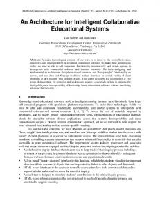
3 Mermaid simulation environment The simulation environment of Mermaid, which is depicted in Figure 1, is layered rather intuitively. The top layer, referred to as the application level, contains high-
Stochastic appl. descriptions
Annotated applications
Stochastic generator
Annotation translator
Application level
Architecture level
Machine parameters Architecture X
Simulation models
Visualization and analysis tools
Architecture Y
Figure 1. Simulation environment.
level descriptions of the behaviour of application workloads. These descriptions are either stochastic representations of application behaviour, or they consist of the sources of real programs that have been instrumented with annotations describing the exact execution behaviour. Application descriptions may range from full-blown parallel programs to small benchmarks used to tune and validate the machine parameters of the simulation models. Note that we explicitly use the term description since the workloads do not require to be executable at this level. Furthermore, the application descriptions are independent of the underlying architecture. This means that they only have to be made once, after which they can be used to evaluate a wide range of architectures. To drive the architecture simulation models, traces of events, called operations, are generated from the workload descriptions at the application level. An operation represents either processor activity, memory I/O, or messagepassing. The generation of the operation traces is performed by one of two tools, called the stochastic generator and the annotation translator. These trace generators realize the interface between the application and architecture levels. The stochastic generator uses a probabilistic application description to produce “realistic” synthetic traces of operations. This technique represents the behaviour of (a class of) applications with modest accuracy, which can be useful when fast-prototyping new architectures. Moreover, it offers the flexibility to adjust the application loads easily. The annotation translator is a library that is linked together with the instrumented applications, while the annotations simply are calls to the library. By executing the instrumented program, the annotations are dynamically translated into the appropriate trace of operations. Evidently, this tool can model application behaviour significantly more accurately than the stochastic generator at the cost of decreased flexibility. The architecture level consists of the architecture simulation models. Every model has a set of machine parameters that is calibrated with published information or by benchmarking. Furthermore, a suite of tools is provided in order to visualize and analyze the simulation output. Visualiza-
tion of simulation data can be performed both at run-time and post-mortem.
To produce the multiple operation traces that are needed for simulation, both trace generators model concurrent execution by means of threads. This implies that, for example, an instrumented application (using the annotation translator) is a threaded program. Each thread accounts for the behaviour of one processor (or node) within the parallel machine. Whenever a thread encounters a global event, it is suspended until explicitly resumed by the simulator (depicted by the broken arrows in Figure 1). Subsequently, the simulation does not resume a thread until all other threads have reached the same point in simulated time as the suspended thread. When this has happened, no other events can affect the global event within the suspended thread anymore. Therefore, the suspended thread can be safely resumed again. This thread-scheduling scheme, under the control of the simulator, guarantees the validity of the multiprocessor traces at all times.
Communication operations
Computational operations
Computational model
Feedback
3.1 Multiprocessor traces
Application workload
Computational tasks
Communication model
Figure 2. The computational and communication models.
using the communication model might be sufficient. In that case, the task-level operation traces must be directly produced by the trace generator.
3.3 Operations 3.2 Computation versus communication Many applications, and especially scientific applications, running on distributed memory MIMD platforms contain coarse-grained computations alternated with periods of communication. Because these computation and communication phases typically are distinct, we decided to split the simulation of application behaviour into two different models: a computational model and a communication model. This is depicted in Figure 2. Each model operates at a different level of detail, and thus defines its own set of operations. The computational model simulates the application’s computational behaviour. It models the incoming computational operations at a level of abstract machine instructions. Communication operations are not simulated by this model, but are directly forwarded to the communication model. Subsequently, the communication model accounts for the application’s communication behaviour. To address the issues of synchronization and load-balancing properly, it models the computational delays found in between communication requests at the task level. A parallel workload for this model therefore resembles a graph containing computational tasks and global events (communication operations). The computational tasks are derived from the computational model, which constructs them by measuring the simulated time between two consecutive communication operations. This approach results in a hybrid model, which allows for simulation at different abstraction levels. If accuracy is required, then the complete hybrid model can be used. However, if there is only the need for fast prototyping, then just
Both the computational and the communication operations are listed in Table 1. The computational operations, being abstract machine instructions, are based on a load-store architecture. The current set of computational operations can, however, easily be extended or used as a building block for more powerful operations in order to support the modelling of alternative types of architectures. The computational operations are divided into three categories of which the first category consists of operations for transferring data between registers and the memory hierarchy. The second category consists of arithmetic functions that solely operate on registers. Finally, the third category of operations is associated with instruction fetching. As memory values are not considered by the operations, the simulator is not aware of loops and branches. Therefore, the trace generator evaluates loop and branch-conditions, and produces the operation trace for the invocated control flow. This implies that every invocation of a loop body is individually traced and leads to recurring addresses of instruction fetches. Using this kind of abstract machine instructions has several consequences. As the operations abstract from the processors’ instruction sets, the simulators do not have to be adapted each time a processor with a different instruction set is simulated. Moreover, simulation at the level of operations rather than interpreting real instructions yields higher simulation performance at the cost of a small loss of accuracy. On the other hand, the loss of information, such as the lack of register specifications in the operations, prohibits a cycle-
Links
Computational operations load(mem-type, address) store(mem-type, address) load([f]constant) add(type) sub(type) mul(type) div(type) ... ifetch(address) branch(address) call(address) ret(address)
Description Accessing memory
In
CPU
Bus
Performing arithmetic
Out
Cache hierarchy
In Out
Abstract processor
Router In Out
Memory In Out
Instruction fetching
Communication operations send(message-size, destination) recv(source) asend(message-size, destination) arecv(source) compute(duration)
(a)
(b)
Figure 3. The template architecture models. Description Synchronous communication Asynchronous communication Computation
Table 1. Trace events or operations.
accurate simulation of, for example, the processor pipelines. This means that Mermaid is only of limited use for purposes like application debugging or compiler testing. The operations that act as input for the communication model are based on straightforward message passing. Both synchronous (blocking) and asynchronous (non-blocking) communication are supported. Computation performed within the communication model is simulated at task level by means of the compute operation.
4 Architecture modelling The architecture model accounting for computational behaviour involves a single node of the multicomputer, whereas communication behaviour is modelled by a multinode model. Both models are implemented in the objectoriented simulation language Pearl [9]. This language was especially designed for easily and flexibly implementing simulation models of computer architectures.
4.1 Single-node computational model The single-node computational template model allows for simulating the processors and memory hierarchy of a MIMD node. It can be parameterized to represent a wide range of node architectures. Figure 3(a) depicts the computational template model. The CPU component simulates a microprocessor within the node architecture. It supports the operation set described in section 3.3. The cache hierarchy component models the first level cache and, if available, the higher level caches of the memory hierarchy. It supports a setup of multiple processors using a common cache hierarchy. To guarantee
cache coherency in such a configuration, the caches provide a snoopy bus protocol. However, other strategies, like directory schemes, can be added with relative ease. To connect the processors and the cache hierarchy to the memory, the template model defines a bus component. It is a simple forwarding mechanism, carrying out arbitration upon multiple accesses. Changing the bus to a more complex structure, such as a multistage network, can be done without too much remodelling effort. In that case, only a new Pearl module needs to be written, replacing the bus component within the template model. Finally, the memory component simulates a simple DRAM memory.
4.2 Multi-node communication model The communication template model has multiple nodes of which a node is constructed from an abstract processor, a router and multiple communication links. This is shown in Figure 3(b). The nodes are connected in a topology reflecting the physical interconnect of the multicomputer. Each abstract processor component within the multinode model reads an incoming operation trace, processes the compute operations and dispatches the communication requests to a router component. After this point, the router is responsible for further handling the transmission. This may include splitting up messages into multiple packets. Furthermore, the router component routes the resulting and all other incoming messages (packets) through the communication network. For this purpose, it uses a configurable routing and switching strategy. Detailed simulation of a distributed memory multicomputer requires that the single-node computational model is replicated for each of the MIMD nodes taking part in the simulation. Each instance of the single-node model is then assigned to a node within the communication model in order to feed it with the computational tasks and communication operations.
4.3 Shared memory or hybrid architectures The multi-node communication model, with its message passing, intrinsically suggests that the system under inves-
tigation should belong to the class of distributed memory architectures. But, by only using the computational model and configuring it with multiple processors, a shared memory multiprocessor can be simulated. A disadvantage of this approach however, is that simulation can only be performed at the level of computational operations, being the highest level of detail. Subsequently, hybrid architectures can be modelled by both defining multiple processors on a node and using the communication model to interconnect the clusters of shared memory multiprocessors in a message-passing network.
5 Application modelling Simulation of a computer architecture and its consequent evaluation cannot be performed without a realistic application load driving the simulation. As it is the case in architecture modelling, modelling an application load can also be done at various abstraction levels and with different degrees of accuracy. Figure 4 illustrates the workload modelling framework of Mermaid. A workload is either based on a real application, like instrumented programs, or it is synthetic and produced by some stochastic process. Furthermore, both real and synthetic workloads can model computation either at the level of abstract machine instructions or at the level of tasks. Computation at the instruction level is simulated by the single-node architecture model, whereas task level operations are simulated by the multi-node model. Currently, only the generation of reality-based, abstract instruction-level operations is operational, as depicted by the shaded area in Figure 4. We will therefore only focus on application modelling through program instrumentation.
5.1 Program annotations At the application level, the applications are instrumented with annotations that follow the control flow of the program and represent the program’s memory and computational behaviour. Because the description of application behaviour should be architecture independent, the instrumentation of programs takes place at the (user) source level. The annotations are translated into a representation of operations by the annotation translator library. Every variable used in the application has an entry in the so-called variable descriptor table. This table determines whether a variable is global, local, or a function argument. It further contains information on the addresses of variables, whether they are placed in a register or not and the types of the variables. When, for example, an annotation indicates that a variable should be loaded, the generator uses this information to translate the annotation into the appropriate instruction fetch and memory operations. The annotation translator
Application model
Reality based
Stochastic
Instruction level operations
Task level operations
Single-node model
Multi-node model
Architecture level
Figure 4. Application modelling within Mermaid. The large shaded area indicates the modelling path currently supported.
can thus be regarded as a kind of generic compiler. It performs the translation of annotations according to the runtime model and addressing capabilities of the target processor. Annotations describing communication behaviour at the application level directly map onto the operations listed in Table 1. As the associated source and destination parameters of these operations are based on the platform’s physical topology, the modelling of communication still reflects the underlying hardware characteristics. Ideally, such architectural details are not visible at the application level. For this reason, we will use a virtual shared memory model in the future to hide all explicit communication [10]. The instrumentation of applications and the creation of the variable descriptor table are performed automatically for C source programs. The tool which is taking care of these tasks also provides some support for converting singlethreaded programs into multi-threaded programs necessary for the trace generation. For SPMD-like applications, this conversion is fully automated. For other classes of applications, manual tuning of the obtained threaded code is still necessary.
6 Simulation performance To give an indication of the simulation performance of Mermaid, we measured the slowdown for several simulations. The slowdown is defined by the number of cycles it takes for the host computer to simulate one cycle of the target architecture. An exact value for the slowdown cannot be given since it depends on the type of application and architecture that are being modelled. Therefore, a typical value will be used. To determine the slowdown per simulated processor, we examined a simulation model of a multicomputer consisting of T805 transputers and a single-node model of a
Motorola PowerPC 601 using two levels of cache. For a mix of application loads, we measured a typical slowdown of about 750 to 4,000 per processor. So an Ultra Sparc processor running at 143Mhz roughly simulates between 30,000 and 200,000 cycles per second. This is slower than the performance of most direct execution simulators, which typically obtain a slowdown of between 2 and a few hundred [2, 3]. We believe, however, that the simulation efficiency can still be enhanced considerably, making Mermaid more competitive performance-wise. For example, the Pearl simulation language in which the architecture models are written, generates only moderately efficient code. The choice of another modelling language might therefore improve the simulation performance significantly. If fast prototyping of a multicomputer is the primary goal, then the communication model can be used directly. The slowdown of this type of simulation depends heavily on the amount of computation and communication present within the application. Computation can be simulated extremely fast since it is modelled at the level of tasks, whereas communication is simulated in more detail and is thus less efficient. Our measurements indicate that simulation at this level of abstraction results in a typical slowdown of between 0.5 and 4 per processor. This means that an entire multicomputer can be simulated with only a minor slowdown. Another important aspect of multicomputer simulation is the memory usage. Simulators that consume a lot of memory may encounter problems when scaling the simulation to a large number of nodes. Since Mermaid does not interpret machine instructions, it is not necessary to store large quantities of state information during simulation runs. For example, the contents of the memory does not have to be modelled and simulated caches only need to hold addresses (tags), not data. As a consequence, the simulation of parallel platforms is only constrained by the memory consumption of the (threaded) trace-generating applications.
7 Summary In this paper, we presented the Mermaid framework for the performance evaluation of MIMD multicomputer architectures. The simulation environment allows for study of the interaction between software and hardware at different levels, ranging from the application level to the runtime system level. Moreover, architecture simulation is supported at various abstraction levels. If, for example, only fast prototyping is required, then simulation can be performed at a high level of abstraction. If accuracy is required, however, then the simulation environment is capable of simulating at a lower, but less efficient, level of abstraction. Mermaid strives to support the evaluation of a wide range of architectural design options. To allow a high degree of parameterization while warranting a reasonable simulation
performance, detailed simulation is performed at the level of abstract machine instructions, rather than at the level of real instructions. For this purpose, we use a simulation technique that is a combination of execution-driven and tracedriven simulation. The traces driving the simulators consist of events, called operations, which represent processor activity, memory I/O or message-passing communication. To guarantee the validity of these multiprocessor traces, the trace generator is interleaved with the architecture simulator. Because of space limitations, we did not discuss the validation of the simulation models in this paper. Validation results for Mermaid’s accurate mode of simulation can however be found in [10]. The task-level mode of simulation has not yet been validated as it is not yet fully operational.
References [1] R. C. Bedichek. Talisman: Fast and accurate multicomputer simulation. In Proceedings of the 1995 ACM SIGMETRICS Conference, pages 14–24, May 1995. [2] B. Boothe. Fast accurate simulation of large shared memory multiprocessors. Tech. Rep. CSD 92/682, Comp. Science Div. (EECS), Univ. of California at Berkeley, June 1993. [3] E. A. Brewer, C. N. Dellarocas, A. Colbrook, and W. E. Weihl. P ROTEUS: A high-performance parallel-architecture simulator. Tech. Rep. MIT/LCS/TR-516, MIT Laboratory for Computer Science, Sept. 1991. [4] R. G. Covington, S. Dwarkadas, J. R. Jump, J. B. Sinclair, and S. Madala. The efficient simulation of parallel computer systems. Int. Journal in Comp. Simulation, 1:31–58, 1991. [5] H. Davis, S. R. Goldschmidt, and J. Hennessy. Multiprocessor simulation and tracing using Tango. In Proc. of the 1993 Int. Conf. in Parallel Processing, pages 99–107, Aug. 1991. [6] M. Dubois, F. A. Briggs, I. Patil, and M. Balakrishnan. Trace-driven simulations of parallel and distributed algorithms in multiprocessors. In Proc. of the 1986 Int. Conference in Parallel Processing, pages 909–915, Aug. 1986. [7] S. Goldschmidt and J. Hennessy. The accuracy of tracedriven simulations of multiprocessors. In Proc. of the 1993 ACM SIGMETRICS Conference, pages 146–157, May 1993. [8] M. A. Holliday and C. S. Ellis. Accuracy of memory reference traces of parallel computations in trace-driven simulation. IEEE Transactions on Parallel and Distributed Systems, 3(1):97–109, Jan. 1992. [9] H. L. Muller. Simulating computer architectures. PhD thesis, Dept. of Comp. Sys, Univ. of Amsterdam, Feb. 1993. [10] A. D. Pimentel and L. O. Hertzberger. The Mermaid architecture-workbench for multicomputers. Tech. Rep. CS96-04, Dept. of Comp. Sys, Univ. of Amsterdam, Nov. 1996. [11] A. D. Pimentel, J. van Brummen, T. Papathanassiadis, P. M. A. Sloot, and L. O. Hertzberger. Mermaid: Modelling and Evaluation Research in M IMD ArchItecture Design. In Proc. of the High Performance Computing and Networking Conference, LNCS, pages 335–340, May 1995. [12] S. K. Reinhardt, M. D. Hill, J. R. Larus, A. R. Lebeck, J. C. Lewis, and D. A. Wood. The Wisconsin Wind Tunnel: Virtual prototyping of parallel computers. In Proc. of the 1993 ACM SIGMETRICS Conference, pages 48–60, May 1993.