JOURNAL OF ADVANCES IN INFORMATION TECHNOLOGY, VOL. 4, NO. 2, MAY 2013
61
An Artificial Neural Network Based Power Control strategy of Low-Speed Induction Machine Flywheel Energy Storage System Mohamed I. Daoud1, Ayman S. Abdel-Khalik2, A. Elserougi2, A. Massoud1, S. Ahmed3, Nabil H. Abbasy2 1 Qatar University, Qatar,
[email protected] 2 Alexandria University, Egypt 3 Texas A&M University at Qatar, Qatar
Abstract—This study introduces a power control strategy of a flywheel energy storage system (FESS) based on an artificial neural network (ANN) as a current decoupling network to charge/discharge the flywheel for grid connected applications such as grid frequency support/control, power conditioning and UPS applications. The proposed system is a large-capacity low-speed FESS based on a field oriented controlled (FOC) squirrel cage induction machine. The controller is designed to avoid machine overloading while the flywheel is charged/discharged. Additionally, it avoids using the required outer power loop or a hysteresis power controller, hence, simplifies the overall control algorithm. The validity of the developed control system is investigated via computer simulations using MATLAB/Simulink as well as experimental results. The proposed system is also compared with conventional power control strategy with an additional outer power control loop to highlight their equivalence. Index Terms—Flywheel energy storage, artificial neural network, instantaneous power control, indirect field orientation.
I.
INTRODUCTION
Due to the proliferation of non-linear loads, the utility becomes more vulnerable to disturbances such as voltage sags, unbalanced power flow and frequency fluctuations. Therefore, energy storage systems have become an essential part of electrical power utilities as they provide a higher level of power quality and stability. Flywheels as energy storage devices exhibit high performance with grid connected applications such as power conditioning, frequency regulation and voltage sag compensation due to their capability of storing energy in form of kinetic energy depending on the rotating speed and their moment of inertia according to (1);
This work was supported by a National Priorities Research Program (NPRP) grant from the Qatar National Research Fund (QNRF). M. I. Daoud (e-mail:
[email protected]), A. Massoud are with Qatar University at Qatar, Doha, Qatar (e-mail:
[email protected]). A. S. Abdel-Khalik is with the Department of Electrical Engineering, Faculty of Engineering, Alexandria University, Alexandria 21544, Egypt (e-mail:
[email protected]). S. Ahmed is with Texas A&M University at Qatar, Doha, Qatar (email:
[email protected]).
© 2013 ACADEMY PUBLISHER doi:10.4304/jait.4.2.61-68
E=
1 2 2 J (ω max − ω min ) 2
(1),
where E is the amount of storage energy, J is the flywheel moment of inertia and ωmax and ωmin are the maximum and minimum rotating speeds [1]. For instance, when there is an excess or lack in the generated power, the system frequency will be increased or decreased; meanwhile when a fault occurs on the network or a sudden pulsed load is connected, voltage sag will take place [2]-[3]. Therefore, when there is an excess in the generated power compared to demanded power, the difference is stored in the flywheel energy storage system (FESS) through the electric machine which utilizes as a motor. Conversely, when there is an unbalance in the power system, the process is reversed and the flywheel discharges its energy and the machine utilizes as a generator [4] supporting the grid. FESSs have several advantages over other energy storage systems including simple structure with very high efficiency, higher power and energy density with high dynamics and fast response, and longer lifetime with low maintenance requirements [5]-[6]. FESS merely consists of a flywheel, electric machine, power conversion system and bearings [7]-[8] as shown in Fig. 1. The flywheel is the mass in which the kinetic energy is stored and driven via the electric machine; it works as a motor while charging and works as a generator while discharging. Permanent magnet machines are normally employed with high speed flywheels [9]-[10] but induction machines are better economical alternatives for low speed flywheels [11]-[15]. A power conversion system matches the grid with the FESS and it mainly consists of power electronics devices (back-to-back converter). Bearings are used to hold the flywheel (rotor) free to rotate in a certain balanced position. There are two types of bearing, conventional mechanical bearings and magnetic bearings, and the usage of each depends mainly on the desired operating speed and the cost. In case of low speed flywheels, conventional bearings can be used while in case of high speed flywheels, magnetic bearings should be used to reduce friction and losses but their cost is much higher than conventional bearings [16].
62
JOURNAL OF ADVANCES IN INFORMATION TECHNOLOGY, VOL. 4, NO. 2, MAY 2013
The value of ids* can be calculated based on the relation [21]:
Lg
λ m = L m i ds ≈ Fig. 1. Basic scheme of FESS
Controlling the power flow between the FESS and the grid is the main concern of this paper. There are two main power control strategies of the FESS based on the field orientation of the induction machines; the conventional instantaneous power control (IPC) and the direct power control (DPC). The instantaneous power control using a double-closed-loop approach depends on using an outer proportional integral (PI) power controller in cascade with the synchronous frame PI current regulators [17]. This strategy is simple, but the tuning of PI controllers depends on small signal analysis based on the non-linear relation between power and stator current. This leads to a complicated overall control design over the flywheel wide speed range while being charged/discharged. The direct torque/power control approach is supposed to solve this problem [18]-[19]. However, there are always significant torque/power ripples. Increasing the switching frequency reduces the ripple magnitude but with a corresponding increase in inverter losses, which is not appropriate for large power applications. In addition, the converter switching frequency depends on the operating conditions; thus the controller performance may deteriorate during the machine starting and low-speed operation [20]. In this paper, a power control strategy based on artificial neural networks (ANN) is proposed to provide a simple power control strategy which avoids tuning and switching problems. The ANN is employed to develop the reference stator current component based on the grid power level and the flywheel rotating speed. This strategy is compared to the conventional power control strategy. Therefore a simulation study on a 2.2 kW induction machine using MATLAB/Simulink is presented and experimental results are obtained for further investigation. II.
FESS CONTROL STRATEGIES
The main concept of the control strategy depends on charging the IM (flywheel) when there is an excess grid power and discharging it when a certain power is demanded. A back-to-back converter is used, as shown in Fig. 1, to match the power from/to the flywheel with the grid allowing bi-directional power flow. It is required to control the total injected power into the grid and charged to the flywheel for a certain period which depends on the maximum and minimum permissible speeds of the flywheel as stated in (1) and its inertia. The main concern is estimating the stator quadrature current reference component that represents the desired stator power. The three phase currents are referred to the d-q frame; iqs* and ids* are the quadrature and direct current reference values related to torque and flux commands. © 2013 ACADEMY PUBLISHER
V
ωe
(2),
where λm is the magnetizing flux, Lm is the magnetizing inductance, V is the rated phase voltage and ωe is the stator angular frequency. These values are compared to the actual fed back current values iqs and ids and the error signals are applied to current regulators as shown in Fig. 2. Two different strategies based on induction field orientation will be applied on the IM studying the behavior and response of each. There are two types of field oriented control, direct FOC and indirect FOC. The indirect FOC depends on measuring the rotor position while direct FOC depends on estimating the rotor position via flux measurement [17], [22]-[25]. The proposed control strategy based on indirect FOC system supplemented by an ANN-based current decoupling network used to develop the required stator current components based on the required grid power level and flywheel instantaneous speed. This strategy is compared with the conventional instantaneous power control strategy where quadature stator current component is derived based on the instantaneous power error through a PI controller. The machine is controlled via maintaining the flux command ids* constant while the reference iqs* is used to control the machine torque and hence the output power. III. INSTANTANEOUS POWER CONTROL (IPC) The conventional instantaneous power control strategy will be applied to the machine side converter based on the IFOC. The instantaneous stator active power is measured, via measuring the machine voltages and currents according to (3) [21], then compared to the desired value supposed to be supplied by the flywheel which depend on the state of the grid, and the errors in both powers will be applied to power regulators; then the outputs represents the current commands which are applied to the current regulators.
3 3 3 2 2 2 Ps = (vdsids + vqsiqs ) = rs (iqs + ids ) + rriqr +T mωm 2 2 2
(3)
This technique will add an external power control loop outside the current regulation loop applied in the indirect field oriented control which increases the stability of the system and its robustness to external disturbances. This strategy has more accurate response as the control is performed on the instantaneous power values but it increases the controller effort and tuning problems, therefore a proposed control strategy based on ANNs will be compared to the IPC performance. The general block diagram for the current decoupling network is depicted in Fig. 3. IV. PROPOSED POWER CONTROLLER VIA ANN The power control via ANN aims to estimate the stator quadrature current without extra control loops.
JOURNAL OF ADVANCES IN INFORMATION TECHNOLOGY, VOL. 4, NO. 2, MAY 2013
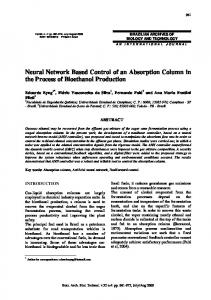
A current decoupling network based on ANN is proposed to generate the quadrature stator current component based on (3). A multilayer feed forward ANN [26]-[27] is employed as a nonlinear function approximator to generate this value based on the flywheel rotational speed and the required grid power level which is limited by charging and discharging power limits. These limits are mainly dependent on the instantaneous flywheel speed. A 2-20-1 ANN controller is used where the number of neurons in the hidden layer is chosen by trial and error method. Hyperbolic tan (tan-sigmoid) and linear activation functions are used in the hidden and output layers respectively. The steady state equation given in (3) is used to generate the training data for the ANN for certain ranges of machine speed and grid power. A 73731 input/output pattern is obtained, where 51611 samples are used to train the proposed ANN and 11060 samples for validating and testing the ANN. The training is performed off-line with the ANN toolbox under MATLAB using the Levenberg– Marquardt training algorithm. The training stops when the mean squared error (MSE) between targets and network outputs decays to a satisfactory level of 5.8 × 10¹³ , as shown in Fig. 5a. Also, the difference between the target and the ANN output for different samples is shown in Fig. 5c; it is clear that the error corresponding to all
i ds
*
samples is within accepted limits ±1 × 10⁻⁵. ANNs give a fast execution speed due to their parallel processing feature; in addition they will decrease the number of controllers, hence reducing the controller effort and the tuning problems. To deliver the grid power, the grid side converter is controlled via controlling the DC link voltage to be constant. The grid voltages and currents are transformed into the d-q frame. The desired DC link voltage is compared to its actual value and the error is applied to voltage regulators providing the active power reference. The grid reactive power is set to zero for a unity power factor operation. The grid angle is measured via phase locked loop (PLL). A block diagram for the proposed control system is shown in Fig. 4. V.
SIMULATION RESULTS
In this section, a simulation case study of FESS control strategies is proposed. The simulation results of both control strategies are presented using MATLAB/Simulink; the results are shown in Fig. 6. The applied IM ratings and parameters are available in the appendix. A three phase grid which is emulated by a three phase supply of 400 V and a DC link of 600 V which are
e ds
i ds
v ds v qs dq → abc
i qs
63
v sabc
v gabc
}
abc ← dq
θg
*
iqs
isdq
θs
ωe
1 p
v qg eqg
Vdc
θs
eqs
θs
igdq
i s −3φ
dq ← abc
iqg
Lg
ωr d dt
v dg edg
θr
ig −3φ
ω slip
θg
isdq
idg * iqg
v g −3φ
θg
* idg =0
Vdc
Vdc Vdc*
Lr / rr
Fig. 2. Indirect field oriented control
i sdq
Qs
v sdq
Ps
i ds
* s
P
Fig. 3. Power control via ANN
© 2013 ACADEMY PUBLISHER
Ps
*
i qs
*
i ds
*
Ps*
ωm
i qs
*
Fig. 4. Instantaneous power control
64
JOURNAL OF ADVANCES IN INFORMATION TECHNOLOGY, VOL. 4, NO. 2, MAY 2013
applied to the FESS which is driven by a three phase wye connected squirrel cage induction machine. The system is
employed to support 500 W to the grid via a back-to-back converter.
(a)
(b)
Fig. 5. ANN analysis (a) MSE variation under training (b) error for different samples
1000
7
800
6 ANN IPC Ref.
600
ANN IPC
5 Current (A)
Power (W)
400 200 0
4 3
-200
2
-400
1
-600 -800
5
6
7
8
9 10 11 Time (sec)
12
13
14
0 5
15
6
7
8
9
12
13
14
15
(b)
(a) 2
ANN IPC
1400
1.5
1300
1
ANN IPC
0.5
1200
Current(A)
Flywheel Speed (rpm)
10 11 Time (sec)
1100
0 -0.5 -1
1000
-1.5
900 800
-2 -2.5
5
6
7
8
9 10 11 Time (sec)
(c)
12
13
14
15
5
6
7
8
9
10 11 Time (sec)
12
13
(d)
Fig. 6. Simulation Results: IPC vs. ANN (a) stator power, (b) stator direct current, (c) flywheel speed, (d) stator quadrature current.
© 2013 ACADEMY PUBLISHER
14
15
JOURNAL OF ADVANCES IN INFORMATION TECHNOLOGY, VOL. 4, NO. 2, MAY 2013
8
1500 IPC ANN
IPC ANN
7
1000
D ire c t C u rre n t(A )
6 5
500
P o w e r(W )
65
4
0
3 2
-500
1 -1000 15
20
25
30
35
40 45 Time(sec)
50
55
60
65
0 15
20
25
30
35
(a)
40 45 Time(sec)
50
55
60
65
(b)
900
4
IPC ANN
F ly w h e e l S p e e d (rp m )
700 600 500
IPC ANN
3 Q u a d ra tu re C u rre n t(A )
800
2 1 0
-1
400
-2
300
-3
200 15
20
25
30
35
40 45 Time(sec)
50
55
60
65
(c)
-4 15
20
25
30
35
40 45 Time(sec)
50
55
60
65
(d)
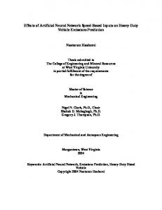
Fig. 7. Experimental results: IPC vs. ANN (a) stator actual power, (b) stator direct current, (c) flywheel speed, (c) stator quadrature current.
Simulation results shown in Fig. 6 illustrate that there are no major differences between both of control strategies; where the FESS exhibits good response while charging and discharging of the flywheel. When the flywheel is charged to a certain speed and a stator power is required to be extracted, the controller starts to decelerate the machine speed discharging the flywheel as shown in Fig. 6c; the machine starts to supply the required power to the grid via the back-to-back converter as shown in Fig. 6a. After supplying the required power, the controller starts to charge the flywheel to a certain speed storing energy in the FESS. The charging and discharging processes are based on the stator power reference. The machine quadrature current is negative during discharging and positive during charging as shown in Fig. 6d. The direct current component shown in Fig. 6b illustrates that the ANN based strategy has a better response during transients under power variation between charging and discharging. The instantaneous power control strategy exhibits better response during steady state with better dynamics. The steady state error of the required power is almost eliminated. Generally, the addition of an external power control loop increases the stability of the system and its robustness to external disturbances during steady state conditions. VI. EXPERIMENTAL RESULTS © 2013 ACADEMY PUBLISHER
Experimental results for both instantaneous power and ANN based power control are obtained to verify the simulation results; they are shown in Fig. 7. A specific profile of desired power is applied to the control system of both of control techniques and the response of the ANN based power control strategy is evaluated comparing to the instantaneous power control strategy. The ANN is trained on the values obtained based on (3). The grid side is emulated via a DC supply connected in parallel with a high power variable resistance to absorb the discharged power of the flywheel in case of discharging. Fig. 8 shows the experimental setup. Fig. 7 shows the control system behavior for both instantaneous power control and ANN based power control strategies with respect to the reference power. For both control strategies, the actual power tracks the reference power as shown in Fig. 7a. The quadrature current is the main control quantity that determines the output speed and power and it is an indication for the torque scheme. Fig. 7b illustrates the direct current component for both strategies; it is obvious that they are identical. Fig. 7c shows the quadrature current for both control strategies. The quadrature current reaches the maximum allowable value during charging of 3.5 A; then with the speed increase on constant power, the current decreases gradually based on the opposite relation between torque and speed.
66
JOURNAL OF ADVANCES IN INFORMATION TECHNOLOGY, VOL. 4, NO. 2, MAY 2013
Gate Drives & VSI
control strategy for flywheel energy storage applications due to its simplicity and less tuning problems and controller effort.
High Frequency Filter Capacitor DC Link Capacitor
Induction Machine
APPENDIX MACHINE RATINGS AND PARAMETERS TABLE I IM RATINGS
Current Sensors Flywheel eZdsp F28335
CAN Device
Flexible Coupling
Host PC High Power Variable Resistance Speed Sensor
Fig. 8. Experimental setup
When the power reference turns to zero, the quadrature current is ideally supposed to be zero and the speed is supposed to be kept constant, but there are machine losses (friction and core) which appear experimentally. When the power is discharged, the direction of the quadrature current is reversed to apply negative torque. The dips appear in the charging power and quadrature current in the ANN strategy at the 22nd second shown in Fig. 7a and Fig. 7c are caused due to an improper calculation at this moment of the ANN which gives a stray value of the output quadrature current which affects consequently on the output power. Fig. 7d depicts the flywheel speed profile during charging and discharging periods. It is obvious that the speed increases with positive power and decreases with negative power. During the zero power periods, the speed continues the deceleration instead of being constant to overcome the friction and core losses. Thus, there are some verifications can be extracted based on the experimental results; the ANN based system gives the same performance of the instantaneous power control strategy with the advantages that it reduces the controller effort due to the elimination of the outer loop controller and hence eliminating the tuning problems of the outer loops. VII. CONCLUSION A developed power control strategy using artificial neural networks (ANNs) for flywheel energy storage system is proposed and compared to the conventional power control strategy. A simulation case study is presented for both control strategies. The simulation results illustrate the competitive performance of the developed ANN based power control strategy. Then it is verified experimentally that the ANN based power control strategy provides high accurate response as well as the response obtained from the instantaneous power control strategy. Therefore the ANN based control strategy can be considered competitive to the instantaneous power
© 2013 ACADEMY PUBLISHER
Rated phase voltage (V) Rated power (KW) Rated frequency (Hz) Full-load current (A) Rated speed (rpm)
230 2 50 4.7 1410
TABLE II IM PARAMETERS
Stator resistance Stator leakage reactance Rotor referred resistance Rotor referred reactance Magnetizing reactance No. of poles Inertia constant H (sec) Flywheel inertia J (kg.m2)
3.335 2.48 6.395 2.48 55.6 4 3.08 3.93
ACKNOWLEDGMENT This publication was made possible by NPRP grant 091001-2-391 from the Qatar National Research Fund (a member of Qatar Foundation). The statements made herein are solely the responsibility of the authors. REFERENCES [1] Ribeiro, P.F.; Johnson, B.K.; Crow, M.L.; Arsoy, A.; Liu, Y.; "Energy storage systems for advanced power applications," Proceedings of the IEEE, vol.89, no.12, pp.1744-1756, Dec 2001.H. Simpson, Dumb Robots, 3rd ed., Springfield: UOS Press, 2004, pp.6-9. [2] Zhang Jiancheng; Huang Lipei; Chen Zhiye; Wu Su; "Research on flywheel energy storage system for power quality," Power System Technology, 2002. Proceedings. PowerCon 2002. International Conference on, vol.1, no., pp. 496- 499 vol.1, 13-17 Oct 2002. [3] Hak-in Lee; Ki-hyun Ji; Eun-Ju Yoo; Young-Woo Park; Noh, M.D.; , "Design of a micro flywheel energy storage system including power converter," TENCON 2009 - 2009 IEEE Region 10 Conference , vol., no., pp.1-6, 23-26 Jan. 2009. [4] Lazarewicz, M.L.; Rojas, A.; "Grid frequency regulation by recycling electrical energy in flywheels," Power Engineering Society General Meeting, 2004. IEEE, vol., no., pp.2038-2042 Vol.2, 10-10 June 2004. [5] Zhongwei Chen; Xudong Zou; Shanxu Duan; Huarong Wei; , "Power conditioning system of Flywheel Energy Storage," Power Electronics and ECCE Asia (ICPE & ECCE), 2011 IEEE 8th International Conference on , vol., no., pp.2763-2768, May 30 2011-June 3 2011. [6] Meng, Y.M.; Li, T.C.; Wang, L.; "Simulation of controlling methods to flywheel energy storage on charge section," Electric Utility Deregulation and Restructuring and Power Technologies, 2008. DRPT 2008. Third International Conference on , vol., no., pp.2598-2602, 6-9 April 2008.
JOURNAL OF ADVANCES IN INFORMATION TECHNOLOGY, VOL. 4, NO. 2, MAY 2013
[7] Jiancheng Zhang; , "Research on Flywheel Energy Storage System Using in Power Network," Power Electronics and Drives Systems, 2005. PEDS 2005. International Conference on , vol.2, no., pp. 1344- 1347, 28-01 Nov. 2005. [8] Sough, M.L.; Depernet, D.; Dubas, F.; Boualem, B.; Espanet, C.; "PMSM and inverter sizing compromise applied to flywheel for railway application," Vehicle Power and Propulsion Conference (VPPC), 2010 IEEE, vol., no., pp.1-5, 1-3 Sept. 2010. [9] R. Okou, A. Sebitosi, M. Khan, P. Barendse, P. Pillay, Design and analysis of an electromechanical battery for rural electrification in sub-Saharan Africa, IEEE Transactions on Energy Conversion 26 (December (4)) (2011) 1198–1209. [10] T. Nguyen, K. Tseng, S. Zhang, H. Nguyen, A novel axial flux permanent-magnet machine for flywheel energy storage system: design and analysis, IEEE Transactions on Industrial Electronics 58 (September (9)) (2011) 3784– 3794. [11] S. Hahn, W. Kim, J. Kim, C. Koh, S. Hahn, Low speed FES with induction motor and generator, IEEE Transactions on Applied Superconductivity 12 (1) (2002) 746–749. [12] D. Eisenhaure, J. Kirtley Jr., L. Lesster, Uninterruptible power supply system using a slip-ring, wound-rotor-type induction machine and a method for flywheel energy storage, U.S. Patent 7,071,581 (2002). [13] H. Akagi, H. Sato, Control and performance of a flywheel energy storage system based on a doubly-fed induction generator-motor for power conditioning, in: Conf. PESC 99, vol. 1, 1999, pp. 32–39. [14] H. Akagi, H. Sato, Control and performance of a doubly fed induction machine intended for a flywheel energy storage system, IEEE Transactions on Power Electronics 17 (January (1)) (2002) 109–116. [15] L. Wang, J. Yu, Y. Chen, Dynamic stability improvement of an integrated offshore wind and marine-current farm using a flywheel energy-storage system, IET Renewable Power Generation 5 (September (5)) (2011) 387–396. [16] Jiancheng Zhang; Zhiye Chen; Lijun Cai; Yuhua Zhao; , "Flywheel energy storage system design for distribution network," Power Engineering Society Winter Meeting, 2000. IEEE , vol.4, no., pp.2619-2623 vol.4, 2000. [17] Cimuca, G.; Breban, S.; Radulescu, M.M.; Saudemont, C.; Robyns, B.; "Design and Control Strategies of an Induction-Machine-Based Flywheel Energy Storage System Associated to a Variable-Speed Wind Generator,"Energy Conversion, IEEE Transactions on , vol.25, no.2, pp.526-534, June 2010. [18] E. Tremblay, S. Atayde, A. Chandra, Comparative study of control strategies for the doubly fed induction generator in wind energy conversion systems: a DSPbased implementation approach, IEEE Transactions on Sustainable Energy 2 (July (3)) (2011) 288–299. [19] H. Nian, Y. Song, P. Zhou, Y. He, Improved direct power control of a wind turbine driven doubly fed induction generator during transient grid voltage unbalance, IEEE Transactions on Energy Conversion 26 (September (3)) (2011) 976–986. [20] M. Mohseni, S.M. Islam, M.A.S. Masoum, Enhanced hysteresis-based current regulators in vector control of DFIG wind turbines, IEEE Transactions on Power Electronics 26 (January (1)) (2011) 223–234. [21] Novotny, D. W. and T. A. Lipo (1996). Vector Control and Dynamics of Ac Drives, Clarendon Press.
© 2013 ACADEMY PUBLISHER
67
[22] Samineni, S.; Johnson, B.K.; Hess, H.L.; Law, J.D.; , "Modeling and analysis of a flywheel energy storage system for Voltage sag correction," Industry Applications, IEEE Transactions on , vol.42, no.1, pp. 42- 52, Jan.-Feb. 2006. [23] Satish Samineni, Brian K Johnson, Herbert L Hess and Joseph D Law "Modeling and Analysis of a Flywheel Energy Storage System with a Power Converter Interface", International Conference on Power Systems TransientsIPST 2003 in New Orleans, USA. [24] Cardenas, R.; Pena, R.; Asher, G.; Clare, J.; , "Control strategies for energy recovery from a flywheel using a vector controlled induction machine," Power Electronics Specialists Conference, 2000. PESC 00. 2000 IEEE 31st Annual , vol.1, no., pp.454-459 vol.1, 2000. [25] Cardenas, R.; Pena, R.; Asher, G.M.; Clare, J.; BlascoGimenez, R.; , "Control strategies for power smoothing using a flywheel driven by a sensorless vector-controlled induction machine operating in a wide speed range,"Industrial Electronics, IEEE Transactions on , vol.51, no.3, pp. 603- 614, June 2004. [26] Abdel-Khalik, A.S.; Elserougi, A.; Massoud, A.; Ahmed, S.; ''Control of Doubly-Fed Induction Machine Storage System for Constant Charging/Discharging Grid Power Using Artificial Neural Network'', in a conference PEMD 2012, Power Electronics, Machines and Drives Conference. [27] P. Vas, Artificial-Intelligence-Based Electrical Machines and Drives— Application of Fuzzy, Neural, Fuzzy-Neural and Genetic Algorithm Based Techniques, Oxford University Press, New York, 1999.
BIOGRAPHIES Mohamed I. Daoud was born in Alexandria-Egypt in November 1987. He received his B.Sc, degree in Electrical Engineering from Alexandria University, Egypt in 2009. His research interests are solid-state power conversion, electric machines, electric machine simulation and energy storage systems. Ayman S. Abdel-Khalik was born in Alexandria-Egypt in July 1979. He received his B.Sc, and M.Sc. degrees in Electrical Engineering from Alexandria University, Egypt in 2001 and 2004 respectively. He received his Ph.D degree in May 2009 under a dual channel program between Alexandria University and Strathclyde University, Glasgow, UK. His research interests are electrical machine design, electric machine simulation, mathematical modeling and electric drives. Ahmed A. Elserougi received the B.Sc. , M.Sc. and Ph.D. degrees in electrical engineering from the Faculty of Engineering, Alexandria University, Egypt, in 2004, 2006 and 2011, respectively. He is currently a lecturer at the Electrical Department, Faculty of Engineering, Alexandria University, Egypt. His research interests include Power Quality, HVDC and FACTS, Renewable Energy and Electric power utility. Ahmed Massoud received the B.Sc. (first-class honors) and M.Sc. degrees from The Faculty of Engineering, Alexandria University, Alexandria, Egypt, in 1997 and 2000, respectively, and the Ph.D. degree in electrical engineering from the Department of Computing and Electrical Engineering, Heriot– Watt University, Edinburgh, U.K., in 2004. His research interests include power quality, active power filtering, distributed generation, and multilevel converters.
68
JOURNAL OF ADVANCES IN INFORMATION TECHNOLOGY, VOL. 4, NO. 2, MAY 2013
Shehab Ahmed was born in Kuwait City, Kuwait in July 1976. He received the B.Sc. degree in Electrical Engineering from Alexandria University, Alexandria, Egypt, in 1999; the M.Sc. and Ph.D. degrees from the Department of Electrical & Computer Engineering, Texas A&M University, College Station, TX in 2000 and 2007, respectively. His research interests include mechatronics, solid-state power conversion, electric machines, and drives. Nabil H. Abbasy was born 1956. He received the B.Sc. (Hons.) and M.Sc. degrees from the University of Alexandria, Alexandria, Egypt, in 1979 and 1983, respectively, and the Ph.D. degree from Illinois Institute of Technology, Chicago, in 1988. . His research interests include power systems operation, dynamics, and transients.
© 2013 ACADEMY PUBLISHER