with the operating room (O/R) team through live audio and video, and view ..... A second, smaller window provides live video from a bird's eye view of the.
An Integrated Remote Neurosurgical System B. Sean Graves, Joe Tullio, Minyan Shi, J. Hunter Downs III �sgraves,tullio,mys2b,downs]@virginia.edu Neurovisualization Lab, University of Virginia, Charlottesville, VA 22903, USA
Abstract
The Neurovisualization Lab at the University of Virginia is developing the Integrated Remote Neurosurgical System (IRNS) to allow mentoring of neurosurgical procedures in remote locations. The system allows a remote neurosurgeon to control a robotic microscope through the use of a 3-D input device, communicate with the operating room (O/R) team through live audio and video, and view presurgical imagery. The surgical team in the O/R will have access to the same images and communication facilities. The system will serve as a training tool through the use of a complete robotic simulation we have developed. We have also instituted safety precautions in the form of restriction of robot motion, monitoring, and protocols of system use. We have developed a registration system to assist in the implementation of these guidelines. A task analysis has led to the development of a prototype user interface, and the preliminary integration of available components has been completed. We report on the current state of the system and ongoing development with respect to the user interface and experimentation.
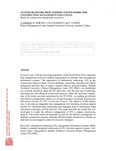
1 Introduction New computer and communications technologies, coupled with advances in microscope and manipulator design, have made it possible to extend the capabilities of neurosurgeons into previously inaccessible locations, such as under-served rural and inner city environments or battle�eld situations. We are constructing the Integrated Remote Neurosurgical System (IRNS), a remotely-operated neurosurgical microscope with high-speed communications and a surgeon-accessible user interface. The IRNS will allow high-quality bidirectional mentoring in the neurosurgical suite. Our research goals are twofold: to �rst provide an integrated training environment and subsequently to develop a clinical system allowing a remote neurosurgeon to lend expertise to the O/R-based neurosurgical team. The IRNS uses a generic microscope/transport model, allowing a wide range of operating room equipment to be controlled. In our case, the equipment will be the Carl Zeiss 1] MKM surgical microscope/transport, currently in use at the University of Virginia Health Sciences Center. See Figure 1 (right). Translation from generic commands to hardware-speci�c transport commands is performed by SuMIT (the Surgical Manipulator Interface Translator). A SuMIT interface has been developed for the Robotics Research 1607 2] industrial robot arm for testing purposes until the MKM becomes available. See Figure 1 (left).
Fig. 1.
Robotics Research 1607 with Puma 260 inset (left), Zeiss MKM (right)
To the remote surgeon, the most important aspect of the IRNS is the Remote Planning and Navigation Workstation. The workstation incorporates surgical planning capabilities and can display real-time video from both the microscope and an overhead video camera. It also incorporates the ability to remotely position the microscope head. The remote workstation includes a small desktop robot that the surgeon positions to e�ect analogous changes in the position of the microscope. See Figure 1 (left inset). Bidirectional audio and image archiving are also available. The training goals of our research are also embodied in the remote workstation. Real-time simulation of the microscope transport is provided by the commercially available simulation package Telegrip from Deneb Robotics 3]. Telegrip is used to produce a realistic view of the microscope and its transport given parameters such as position and velocity. It can provide simulated views from either the microscope or a vantage point in the virtual O/R. Most importantly, it permits pre-surgical simulation, post-surgical critique, and training for surgeons without access to an actual microscope transport system. The components of the IRNS are currently integrated using TCP/IP networking. Guidelines have been devised to ensure safe system operation both during normal operation (i.e. transport control hando�, collision avoidance) and under error conditions (i.e. loss of communication, transport failure, O/R emergencies). A registration system has been developed to ensure precise monitoring
of the patient and microscope. The IRNS provides an opportunity to assess the bene�ts of remote surgical mentoring. By integrating high performance workstations and microscope carriers, the system demonstrates the usefulness of communications and computing resources in improving access to specialized surgical facilities. This research, along with the more sophisticated systems that will follow, will serve as a foundation and testing platform for extending the surgeon's skills without regard to time zone or geographic boundaries. This document will describe the IRNS in its current state, including the system architecture, communications architecture, safety guidelines, user interface, and hardware. We will then discuss the future research and development goals for the IRNS.
2 IRNS System Architecture 2.1 Overview
The IRNS consists of two worksites, the operating room and the remote workstation. They are connected via a TCP/IP network. Each worksite hosts several architectural elements, such as workstations and cameras. Locally, these elements are interconnected by Ethernet or RS-232 connections, and are ultimately linked by a site workstation. A TCP/IP link is responsible for carrying all video, audio, and control data. Since the MKM is frequently in use at the UVa Health Sciences Center O/R, the system is currently simulating the MKM in Telegrip and using a Robotics Research 1607 7 degree-of-freedom robot arm instead. The network, room camera software, audio communications, optical registration system, and user interface are all present.
2.2 Communications Design
Live video is transmitted between the remote and local sites over a TCP/IP network. The video is captured using the JPEG compression/decompression capabilities of Parallax Graphics 4] video hardware installed on each workstation. Audio communication is currently provided by an innovative networking scheme called the MBONE 5], a virtual network built on top of the Internet. MBONE routers transmit multicast (e.g., audio/video) packets which are wrapped with IP headers for transmission through intervening Internet routers. The actual audio tool, vat 6], is freely available software that uses the MBONE. For transmission of image data and control/feedback information, both locally and remotely, we use TelRIP 7], a general purpose data exchange system for use with TCP/IP networks. TelRIP uses a data-centered approach to modularity, meaning that programs communicate with one another by specifying the types of data they wish to send or receive. An advantage is that our processes can continue to run without knowing the state of other processes on the network. This approach also allows us to standardize the interfaces to devices and controls without predetermining the exact implementation of each interface.
2.3 O/R Worksite The O/R worksite consists of the following components:
{ { { {
A surgical stereomicroscope mounted on a robotic transport, One or more `bird's eye' view cameras on pan/tilt heads, An optical registration system, and A workstation to display and annotate pre-surgical and inter-operative medical imagery.
Live video from both the stereomicroscope and the O/R view camera(s) is routed through JPEG compression hardware before transmission across the TCP/IP link and is subsequently decompressed, again in hardware, at the remote location. The O/R \bird's eye" view cameras were included to give the remote surgeon feedback on the situation in the O/R. This type of feedback is known to improve the interactivity of collaborative systems 8] by giving the remote user a sense of presence at the local site (in this case, the O/R). The optical registration system, Image Guided Technologies' Flashpoint 5000
9], is also interfaced to the overall system via the O/R workstation. This component is used to calculate the relative positions of the robot base and patient by sensing targets which are placed on them. Locations of these objects are represented internally as a series of coordinate systems. These locations facilitate monitoring of the patient's position relative to the microscope. A simulated version of this system is also available for training purposes. The workstation can display views from the stereomicroscope, pre-surgical MR and CT images, and 3D surgical planning images. Users in the O/R can interactively slice through patient data, zoom in on images, and view a rendered volume of the brain. In addition, verbal communication between the O/R and the remote site is provided through microphones, speakers, and MBONE transmission of audio.
2.4 Remote Worksite The remote worksite consists of a graphics workstation providing:
{ Robotic transport control, { Video from the microscope and O/R view cameras, and { Surgical planning facilities. Microscope transport positioning control can be performed in three ways:
{ Graphically - The surgeon can manipulate the graphical user interface (GUI) to translate the microscope. { Analogically - The surgeon can position a desktop robot arm to e�ect an analogous orientation of the microscope.
{ Verbally - The surgeon can issue commands to the microscope by speaking.
Facilities on the layout of the GUI allow the surgeon to pan the microscope using arrow buttons. These buttons can be activated either by using the mouse or by pressing the touchscreen. The system uses a small 6 degree-of-freedom robotic arm which �ts on a desktop. This arm, the Puma 260 from Unimation 10], is �tted with a handgrip that the surgeon can hold to move the arm. The joint angles and positions are then used to create an analogous position for the microscope transport. This new position is sent over the TCP/IP network to the O/R, where it is received by the transport. This type of controller gives the surgeon an intuitive way to guide the microscope transport, simply by pushing or pulling on the handgrip. It also provides �exibility for future improvements such as force re�ection, dexterity enhancement 11], and the capability of returning to previous positions. In addition, verbal commands to the system's speech recognition software, Speech Systems Phonetic Engine 500 12] allow the remote surgeon to control translation of the microscope simply by speaking commands such as \pan left" or \pan up". Feedback from the O/R is provided in video and audio forms. The remote surgeon is presented with live video from both the microscope and the O/R camera views. A graphical simulation of the microscope transport's current position is also shown to give the surgeon a better feel for the spatial con�guration of the patient, microscope, and transport. Snapshots of the view through the microscope can be taken and saved along with the positioning information necessary to return the transport to the snapshot view. Annotations provided through the system's whiteboarding facility are also saved. To return the microscope to the position from which snapshots were taken, commands may be issued via the graphical user interface or by verbal command. The surgical planning and audio facilities are identical to those on the O/R workstation.
3 Safety Precautions The responsibility of overall system safety is divided between four di�erent methods: { Restriction of Robot Motion - The robot's motion is limited to a speci�ed safety envelope. { Registration of Critical Objects - The precise locations of the patient and microscope must be known at all times. { Implementation of an Operation Protocol - Users must follow a rigid set of procedures during the system's use. { Installation of Safety Hardware - A set of safety processors ensure that the robot is functioning normally. To avoid collisions, the robot's motion is restricted �rst to a working volume, the set of all points which can be physically reached by the robot. The Telegrip package can graphically display this work volume. On a second, smaller level, the working volume must be constrained by the patient and the operating
area. Generally speaking, motion will be constrained within a spherical safety envelope above the operating area. More detailed speci�cations on the MKM are being acquired to accurately calculate this envelope. Registration becomes necessary in order to calculate the safety envelope and monitor the locations of both patient and robot. We have developed both simulated and physical versions of the registration system. The registration system consists of two components: the optical registration system in the O/R and the user interface at the remote site. While the optical system measures both the locations of the patient and the robot base, the user interface provides the surgeon's intended location of the microscope relative to the patient. These coordinate systems are then combined to provide a measurement of the location of the robot with respect to the patient. Motion commands from the user interface will be checked at the O/R for safety limitations based on this registration to ensure that the robot does not move outside of its safety envelope. SuMIT then performs the low-level translations necessary to convert positions in these internal coordinate systems into robot-speci�c motions. Another important problem in maintaining the safety of the robot's motion is the avoidance of singularities. These are con�gurations of the robot arm where certain directions of motion may be unattainable. They often correspond to points on the boundary of the robot's workspace, out of its maximum reach. The key to avoiding singularities is to keep the working volume of the robot within its dextrous workspace, which is the set of all points that the robot can reach with an arbitrary orientation of the tool. Singularities are determined by the structure and parameters of a particular robot. They can be calculated and shown on a package such as Telegrip. The IRNS software is designed to recognize singularities and provide feedback to the surgeon should the robot approach one. This feedback is currently given by color-coding the a�ected joints in Telegrip, but can be provided later through force feedback in the remote surgeon's input device (the desktop robot arm). Both the O/R and remote sites can control the robot, although not at the same time. Hando� of control between the two sites will be negotiated between the remote surgeon and the team in the O/R site. A single \dead man's switch" interface ensures that only one party has control of the microscope at any given time. The robot is in a stopped state upon startup and shutdown of the system. Should communication between the remote and local parties be severed, aborted commands are retried until they are timed out. The local team in the O/R always has the option to assume sole control of the robot. In short, the local team is able to continue the procedure should communication with the remote surgeon be lost. The MKM system is equipped with a number of safety processors which monitor the robotic arm for failures such as excessive velocity and range limits. Procedures for recovery from failures related to these safety processors will be followed in accordance with the MKM manuals 13]. The Robotics Research arm in our prototype, however, is equipped with no such circuitry. Safety routines pertaining to this arm will consequently be handled in software.
4 Graphical User Interface Design
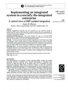
Fig. 2.
Layout of remote workstation interface
4.1 Task Analysis Feedback from surgeons and residents has been sought throughout the project's development. Observations of surgeons using robotic microscopes have been conducted at the University of Virginia hospital, and have also been reviewed on video logs. In addition, our lab has assisted in training surgeons and residents on the use of the MKM. Our observations are critical in determining the current de�ciencies in the usability of the surgical microscope as well as the interaction style to which the surgeons have become accustomed. Our system can correct some of the observed problems (operating table movement, jerky motion of the microscope) because of the increased �exibility a�orded by its remote interface and registration system. Interviews were also conducted to determine what major functions are desired by surgeons. Features which came out of this process include speech recognition capabilities, a simulated view of the microscope (through Telegrip), and an image archiving facility.
In addition to the design criteria speci�ed by the task, current research concepts from the areas of robotic control paradigms and human-computer interaction were included in the design. The selection of input devices and the graphical user interface layout (Figure 2) and interaction style were in�uenced in part by previous research 14] 11].
4.2 Interface Design A layout for the remote console (see Figure 2) has been designed to conform to the needs of the surgeon. It represents the result of feedback received from surgeons and lay users as well as from our ongoing task analysis. The GUI currently includes:
{ A large window which displays live video from the microscope. This window
is surrounded by arrow buttons which allow translation of the microscope on two axes. This control serves as a limited backup to the desktop input device. { A second, smaller window provides live video from a bird's eye view of the operating room. Controls on the window allow the surgeon to pan the camera in 4 directions as well as zoom. The window is also equipped with a \point and click" interface 15]. If the surgeon clicks (or touches) any point on the O/R video, the camera will automatically center that point. The surgeon can specify a region to zoom to by sweeping out a box on the O/R video window using the mouse or touchscreen. { Two more windows provide views of the patient's MRI data and a rendered image of a segmented volume of this data. The surgeon can easily zoom and slice through the data using thumbwheel-style widgets beneath the windows. { A \snapshot" facility allows the surgeon to record still images from the microscope camera and store them. A separate window normally displays the most recent snapshot, but a history menu of thumbnail images lets the user select an older snapshot to display. Annotations made to the images through whiteboarding are saved with the snapshots. The state of the microscope is also saved with each snapshot. This a�ords the capability of returning the microscope transport to the position from which a snapshot was taken. All video displays in the GUI are capable of displaying computer graphics over the video stream. This facilitates a simple whiteboarding facility whereby the surgeon can annotate the display using a mouse or touchscreen. As the surgeon draws on the display, the notations are simultaneously transmitted to the O/R and displayed on the local GUI. These notations can be saved along with video snapshots from the microscope to provide a record of the procedure. A touchscreen from Trident Systems 16] is present at both the remote and local sites. It provides a simple interface in that the remote surgeon or O/R team can directly interact with GUI elements instead of using a mouse to indirectly position the cursor. Combined with the GUI layout, the touchscreen eliminates the need for a mouse or keyboard when operating the basic functions of the
interface. This is important because desktop space in an O/R is very limited. The touchscreen is also more conducive to sterilization. A speech recognition system has been integrated into this prototype for use in issuing verbal commands. Most of the GUI functions now have verbal equivalents, such as panning the microscope and taking snapshots of the current microscope view. Response has been positive from our primary consulting surgeon and casual visitors to our lab, so this means of interaction is being enhanced to include more commands. Currently, the user interface is connected to the Telegrip robot simulation package through the use of the TelRIP networking software mentioned above. It is also capable of issuing commands to the Robotics Research arm.
4.3 Robot Simulation Models of both the MKM robotic microscope transport and the Robotics Research 1607 arm were developed in Telegrip so that robot behavior could be simulated when they were not actually available. The simulations are complete, with closed-form inverse kinematics linked into Telegrip through a shared library. The closed-form solutions are more rapid than the iterative ones and, more importantly, are capable of determining the singular positions within the workspace of the microscope transports. The models can be manipulated locally through the Telegrip UI and remotely through any TCP/IP link. Various other components of the O/R have also been modeled in this simulation including the camera, optical tracking system and patient.
5 Ongoing Work The transmission of live video over standard TCP/IP networks is not an ideal method due to high latency. Video frame rates can be diminished, resulting in a poor environment for surgical mentoring. We are currently implementing ATMbased networking to provide audio and video communication. Asynchronous Transfer Mode (ATM) networking is an emerging communications technology in which �xed-length \cells" of data are transferred at speeds of over 2.3 Gbits/sec
17]. The primary advantage of ATM is that it was speci�cally designed for simultaneous data, voice and video transmission - precisely the characteristics required for telemedicine. As stated before, the desktop robot arm provides the capability of force re�ection and dexterity enhancement. We plan to use force feedback to indicate boundaries outside of which the remote surgeon may not move the microscope. The hand controller could also be combined with another tool to allow twohanded interaction that has been shown to improve user performance 18]. In addition, the whiteboarding capabilities in the microscope view will be extended to the snapshot facility and possibly to other areas of the display. The ability to overlay graphics onto our video streams also opens the way for more complex
enhancements such as overlaying of segmented images and augmented reality elements 19]. Because the IRNS is still under development, we have not conducted any formal experiments. When we have a complete prototype implementation we plan to conduct trials with our consulting surgeons in order to take measurements on network loading, operational e�cacy, learning time, and positional accuracy. We have a working prototype which substitutes the industrial Robotics Research arm for the MKM. We expect to have the MKM fully integrated by the summer of 1997.
6 Acknowledgments This work is funded, in part, by the DARPA Grant DAMD17-95-1-5060.
References 1. 2. 3. 4. 5. 6. 7.
Carl Zeiss, Inc. (914) 681-7300. Robotics Research Corp. (513) 831-9570. Deneb Robotics, Inc. (810) 377-6900. Parallax Graphics, Inc. (303) 447-0248. MBone Information Web. http://www.mbone.com. Vat audio tool. Available via anonymous ftp: ftp.ee.lbl.gov/conferencing/vat. J. D. Wise and L. Ciscon, \TelRIP distributed applications environment operating manual," Tech. Rep. 9103, Rice University, Houston, TX, 1992. 8. W. Buxton, \Telepresence: Integrating shared task and person spaces," in Proceedings of Graphics Interface '92, 1992. 9. Image Guided Technologies, Inc. (303) 447-0248. 10. Staubli Unimation, Inc. (803) 443-1980. 11. P. S. Schenker, E. D. Barlow, C. D. Boswell, H. Das, S. Lee, T. R. Ohm, E. D. Paljug, and G. Rodriguez, \Development of a telemanipulator for dexterity enhanced microsurgery," in Proceedings of Medical Robotics and Computer-Assisted Surgery '95, 1995. 12. Speech Systems, Inc. (303) 938-1110. 13. Carl Zeiss, Inc., MKM System: Instructions for Use, 1995. 14. S. Zhai and P. Milgram, \A telerobotic virtual control system," in Proceedings of SPIE, Volume 1612, Cooperative Intelligent Robotics in Space II, 1991. 15. K. Yamaashi, J. Cooperstock, T. Narine, and W. Buxton, \Beating the limitations of camera-monitor mediated telepresence with extra eyes," in Proc. ACM CHI'96 Conference on Human Factors in Computing Systems, pp. 50{57, 1996. 16. Trident Systems, Inc. http://www.tridsys.com/. 17. Newbridge Networks Corporation, (613) 591-3600, ATM and SONET: The Guide to Emerging Broadband Technologies, 1995. 18. W. Buxton and B. Myers, \A study in two-handed input," in ACM CHI '86 Conference on Human Factors in Computing Systems, 1986. 19. P. Milgram, A. Rastogi, and J. J. Grodski, \Telerobotic control using augmented reality," in Proceedings 4th IEEE International Workshop on Robot and Human Communication, 1995. This article was processed using the LATEX macro package with LLNCS style