1028
IEEE TRANSACTIONS ON CIRCUITS AND SYSTEMS—II: EXPRESS BRIEFS, VOL. 62, NO. 11, NOVEMBER 2015
An Ultra-Low-Power RF Energy-Harvesting Transceiver for Multiple-Node Sensor Application Young-Joon Kim, Student Member, IEEE, Hansraj S. Bhamra, Student Member, IEEE, Jithin Joseph, and Pedro P. Irazoqui, Senior Member, IEEE
Abstract—An ultra-low-power wirelessly powered radiofrequency (RF) transceiver for wireless sensor network is implemented using 180-nm CMOS technology. We propose a 98-μW 457.5-MHz transmitter with output radiation power of −22 dBm. This transmitter utilizes 915-MHz wirelessly powering RF signal by frequency division using a true-single-phase-clock divider to generate the carrier frequency with very low power consumption and small die area. The transmitter can support up to 5-Mb/s data rate. The telemetry system uses an eight-stage Cockcroft–Walton rectifier to convert RF to dc voltage for energy harvesting. The bandgap reference and linear regulators provide stable dc voltage throughout the system. The receiver recovers data from the modulated wireless powering RF signal to perform time-division multiple access (TMDA) for the multiple-node system. Power consumption of the TDMA receiver is less than 15 μW. Our proposed transmitter and receiver each occupies 0.0018 and 0.0135 mm2 of active die area, respectively. Index Terms—Energy harvest, low-power wireless transceiver, time-division multiple access (TMDA), wireless sensor network.
I. I NTRODUCTION
R
ECENT advances in low-power transceiver design opened up a new generation of biomedical wireless sensor network application for health monitoring and rehabilitation. However, challenges still remain in realizing miniature size of the device, batteryless operation, and multiple-node accessibility. Federal Communications Commission regulation on radio frequency (RF) exposure to people [1] places a tight constraint on delivering energy, demanding a low-power device design. Moreover, a multiple-node system is required in applications such as targeted muscle reinnervation (TMR) [2], [3], but it is overlooked in many prior works due to a limited power budget. Conventionally, the TMR sensor nodes are attached to the patient’s upper chest and wired to the prosthetic arm. A major bottleneck in the current sensor technology is the use of wired sensors [4] and batteries that limit operation time. The wired surface electrodes suffer from low spatial resolution [5] and require frequent replacements. To overcome these issues, implantable devices have been developed to record the myoelectric activity [6], [7]. Since these devices are implanted, the
Manuscript received April 18, 2015; revised June 12, 2015; accepted July 6, 2015. Date of publication July 16, 2015; date of current version October 30, 2015. This work was supported by the U.S. Department of Defense under Grant N66001-12-1-4029. This brief was recommended by Associate Editor G. Wang. Y.-J. Kim, H. S. Bhamra, and J. Joseph are with the School of Electrical and Computer Engineering, Purdue University, West Lafayette, IN 47907 USA (e-mail:
[email protected];
[email protected];
[email protected]). P. P. Irazoqui is with the Weldon School of Biomedical Engineering, Purdue University, West Lafayette, IN 47906 USA (e-mail:
[email protected]). Color versions of one or more of the figures in this brief are available online at http://ieeexplore.ieee.org. Digital Object Identifier 10.1109/TCSII.2015.2456511
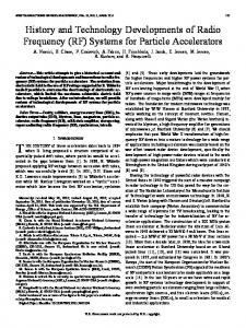
Fig. 1. Proposed sensor network in a (a) wireless sensor network application and (b) TMR.
use of batteries is not desirable because of their bulky size, and replacing a battery leads to a surgical procedure that can cause infections. To eliminate the use of battery, there are various techniques to scavenge ambient energy such as electromagnetic (EM), inductive, thermoelectric, solar, and motion energy [6], [8]–[10]. Unfortunately, inductive energy has very limited link distance, and delivering uniform power to multiple nodes is still a challenge [11]. Thermoelectric energy, solar energy, and motion energy are not applicable in TMR and most medical implant application because such energy sources are beyond user’s control. Thus, the EM energy transfer is considered in this brief for its link distance and controllability. Electromyography (EMG) data requires more than 2 kb/s of sampling rate [2], [3], forcing the transmitter to be active more than other high-duty-cycled sensor nodes [8], [10], which increases the required power of the transmitter. To minimize the power consumption of the transmitter, some have used the passive RF identification technology for data transmission [12], [13]. However, the reader design becomes complicated because it needs to detect weak backscattered signals at the same frequency of power transmission. Additionally, multiple-node operation is another issue that arises in EMG data recording application. There are numerous multiple-access techniques, but due to the complexity and power consumption, time-division multiple access (TDMA) is considered in this application. Multiple-node operation is a problem that is overlooked in most of the literature, and some overcome this by implementing a conventional receiver [8], [14] or changing the strength of the powering signal [15], which leads to a significant overhead in power consumption or loss in available power. To solve the aforementioned issues, we developed an RF energy-harvesting ultra-low-power wireless telemetry system (see Fig. 1) for TMR application that enables new possibilities for the upper-limb prostheses [4]. We introduce an energy-harvesting telemetry system utilizing an RF transceiver with ultra-low-power consumption. A TDMA logic circuit is
1549-7747 © 2015 IEEE. Personal use is permitted, but republication/redistribution requires IEEE permission. See http://www.ieee.org/publications_standards/publications/rights/index.html for more information.
KIM et al.: RF ENERGY-HARVESTING TRANSCEIVER FOR MULTIPLE-NODE SENSOR APPLICATION
1029
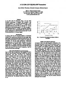
Fig. 2. Proposed system architecture and block diagram.
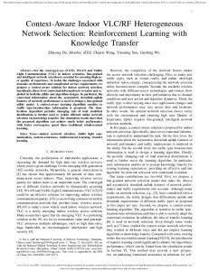
Fig. 3. Schematic of the transmitter.
included in the design to realize multiple-node synchronization with simple and robust operation requiring very little power overhead. The proposed design also consists of an RF rectifier, bandgap reference (BGR), and regulators for energy harvesting and power management. II. P ROPOSED A RCHITECTURE AND C IRCUIT D ESIGN Fig. 2 describes the system architecture in a block diagram. The base station delivers RF energy in the ISM band (915 MHz) to the device. The RF energy has three purposes in this system: power, reference frequency, and multiple-node synchronization. Power is distributed to the energy harvester block where it supplies stable dc supply to the internal device. The frequency of the powering signal is taken to the transmitter where it is halved to avoid self-jamming. The divided frequency is used as the transmission carrier frequency and on–off keying (OOK) modulation is utilized for its simple and power efficient performance. Short off-pulses in the RF powering signal serve as the indicator for multiple-node synchronization. A. Transmitter Fig. 3 shows the schematic of the proposed transmitter. The current-reused and limiting amplifier is used to convert the incident RF signal to a rail-to-rail signal for the frequency divider. A feedback shunt resistor Rf sustains the transistor in saturation, and the stacked transistor structure increases transconductance for the same bias current. The size of M11 and M12 is kept small due to limited power budget and bandwidth degradation from Miller effect associated with (CGSN +CGSP ). A limiting amplifier is formed with a chain of minimumsized inverters. The purpose of this block is to ensure a digitallike signal and reduce the loading effect for the frequency divider to increase the robustness.
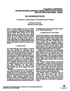
Fig. 4. (a) Types of TSPC dividers and (b) simulation results of maximum achievable frequency and power consumption of the structures at 915 MHz.
A true-single-phase-clock (TSPC) divider is chosen to perform the frequency division for its low power consumption at sub-Gigahertz. Generally, in TSPC frequency dividers, ratioless logic has lower power consumption compared with ratioed logic because, ideally, a direct path from the supply to the ground never happens, and power consumption is determined exclusively by the dynamic switching. However, at the same time, ratioed logic has faster switching time with smaller gate capacitance (CL ) at the cost of robustness [16]. To minimize power consumption at a target frequency, combinations of ratioless logic and ratioed logic are investigated. The simulation results are shown in Fig. 4. Type A has the lowest power consumption, but the speed is below our requirement under the reduced power supply and load introduced by subsequent blocks. Thus, type B is chosen for the lowest power consumption. High-Vt devices were used for the TSPC divider to reduce the leakage current. A power-efficient switching amplifier is used for the power amplifier (PA). For power reduction, a dc voltage of 0.5 V supplies the amplifier. The matching network is implemented with off-chip components. Because the capacitors have higher Q-factor compared with inductors, a tapped-capacitor network has been used to avoid inductors. B. Receiver The receiver (see Fig. 5) is designed to detect very short offpulses of the RF power source with small power consumption
1030
IEEE TRANSACTIONS ON CIRCUITS AND SYSTEMS—II: EXPRESS BRIEFS, VOL. 62, NO. 11, NOVEMBER 2015
Fig. 5. Schematic of the receiver.
because modulation in the RF power source can be considered an overhead in total available power. The amplifier stage is implemented on-chip, which is the same amplifier stage shared with the transmitter to reduce power consumption. The offpulses are demodulated by using an envelope detector that is composed of inverters driving two different RC time constants: one serving as the envelope detector (VENV ) and the other one with a long time constant to give an average of the envelope (VREF1 ). A comparator then digitizes the voltage levels of the two RC circuits for demodulation. The comparator is formed of two differential amplifier pairs with input-referred offset voltage simulated to be less than 10 mV. A Schmitt-trigger inverter stage is cascaded to the comparator to ensure that a reliable rail-to-rail digital signal is present at the output. From the demodulated data, a TDMA logic circuit performs the node synchronization. The transient measurement shown in Fig. 10 explains the operation. When five RF off-pulses are detected within 8 μs of time period, an “event” is triggered. By counting the number of “events,” a “node enable” signal is presented when the event counter matches a preprogrammed number in each device. Each device node also has a preprogrammed cycle number where the “event” counter resets. The maximum number of nodes for synchronization is defined by the number of bits assigned for the preprogrammed number, which is 16 in this design. C. Energy Harvester and Power Management The RF energy harvester block (see Fig. 6) is comprised of an RF rectifier, BGR, and a low dropout (LDO) regulator. An eight-stage Cockcroft–Walton voltage multiplier rectifies and boosts the voltage to a sufficient level with low input signal [17]. Native devices were used in this design for their low voltage drop and tolerable back leakage. We employed two LDO regulators to supply the PA and elsewhere. An off-chip capacitor of 4.7 μF with effective series resistance of 1 Ω is used for stability. The line regulation is measured within 0.1% of its nominal values. The bandgap reference generates a process, voltage, and temperature independent reference for the system [18]. The PMOS current sources of the BGR are cascaded to improve the power-supply rejection ratio.
Fig. 6. Schematic of the energy harvester and power management.
Fig. 7. (a) Die micrograph. (b) Chip assembled with external components.
Fig. 8. (a) Measured transmitter efficiency. (b) Transmitter output spectrum measured at ON-state.
III. E XPERIMENTAL R ESULTS The application-specific integrated circuit was fabricated through 180-nm CMOS process technology [see Fig. 7(a)]. The total area of the test structure, including the pads, is 1.3 mm × 0.7 mm. The assembled transceiver is shown in Fig. 7(b). Off-chip surface-mount device components were used to implement the matching network for the transmitter. The power consumption for the transmitter is measured to be 98 μW while delivering −22 dBm (Agilent E4404B) to the load (Fig. 8(b) and Table I shows the detailed power consumption breakdown). The minimum power required for the input to generate a stable 457.5-MHz carrier is −10 dBm, and the maximum data rate of the transmitter is 5 Mb/s, i.e., 15 pJ/b (see Fig. 9). The startup time of the transmitter is 60 ns, which is fast enough for the proposed receiver and TDMA method. The transmitter occupies die area of 0.0018 mm2 . The receiver shows sensitivity of −10 dBm with power consumption less than 10 μW. The overall power consumption
KIM et al.: RF ENERGY-HARVESTING TRANSCEIVER FOR MULTIPLE-NODE SENSOR APPLICATION
1031
TABLE I P OWER C ONSUMPTION B REAKDOWN FOR T RANSMITTER
Fig. 11. Measurement of (a) VRECT and (b) efficiency respect to input power under various load condition.
Fig. 9. (a) Spectrum measured with modulated input at 1 and 5 Mb/s. (b) Transient waveform of the transmitter with pseudorandom input at 5 Mb/s.
Fig. 12. Experiment setup.
Fig. 10. Transient waveform of the RF input and TDMA operation.
of the TDMA logic circuit consumes 5 μW. The receiver can detect pulses as short as 0.5 μs in the current TDMA operation mode, giving efficiency of 5 pJ/b. Fig. 10 shows the measured TDMA operation. A waveform generator is used to create the trigger pulses for the RF signal generator. To make sure the receiver and the digital block detects an “event,” the input RF signal is configured to have seven off-pulses in 8-μs period. The measurement was taken on a four-node system with three nodes measured due to the limited number of probes in the oscilloscope. It can be seen that the “node enable” signal rises after five off-pulses. In this measurement example, the penalty on the total available power caused by modulating the RF powering signal is less than 7%, which is much lower than other reported work [15]. The entire receiver including the logic circuits occupy 0.0135 mm2 of chip area. Fig. 11 shows voltage measurement at the rectifier under different load conditions. External resistance represents the various loading of the system. The diode connected transistors in the rectifier has a nonlinear behavior, and it is difficult to
optimize the matching network at a wide load range. Thus, a specific load condition that would represent a clinical application is chosen [19]. The overall energy efficiency is over 10% throughout the input power range. The total current consumption of the bandgap reference and voltage regulator is 3 μA. The functionality of the energy harvest, node synchronization, and data transmission was verified under the experimental setup shown in Fig. 12. The experiment was performed in a laboratory environment. The RF energy is delivered by using a signal generator, external PA and a horn antenna. Commercial whip antenna (ANT-916-CW-RCS, Linx Tech) and chip antenna (ANT1204LL05R0915A, Yageo) were used for receiving power where the TDMA synchronization operates flawlessly up to 2.8 and 2.2 m, respectively. Three transceiver nodes were used at the same time for TDMA verification. Transmitter was tested under the same environment with a commercial chip antenna (7488910043, Wurth Elec). A data input pin is connected to a pseudorandom code generator to and the external base station receives and demodulates the signal. The data rate was tested up to 1 Mb/s due to the limitation on the base station. (USRP N210, Ettus) The bit error rate (BER) is measured to be below 0.1% up to 6 m. For in vivo experiments,the work in [20] provides an estimation on how much RF energy can be received in an implant. It is shown that when the transceiver is placed between the adipose and muscle, the maximum achievable distance between the transceiver and the base station can be estimated to be more than 30 cm.
1032
IEEE TRANSACTIONS ON CIRCUITS AND SYSTEMS—II: EXPRESS BRIEFS, VOL. 62, NO. 11, NOVEMBER 2015
TABLE II P ERFORMANCE C OMPARISON OF THE P ROPOSED T RANSCEIVER AND C URRENT T ECHNOLOGY
Table II summarizes the performance of the proposed transceiver with few works that have recently been published. At −10-dBm input power, the transceiver consumes 110 μW while constantly delivering Pout of −22 dBm to the transmit antenna. IV. C ONCLUSION We have presented a low-power wireless telemetry system, powered by an RF energy harvester, for a multiple-node TMR sensor application. The transmitter is designed to have a low power consumption for a batteryless sensor application. The overall system has a stable carrier frequency, high data rate for transmission, and robust TDMA performance while consuming only 110 μW, which is the lowest power level for an active multiple-node telemetry system that has been reported to date. Based on the proposed transceiver, a sensor node system can be designed [21]. For future improvement, an antenna decoupling technique [22] can be included to reduce the system size. The sensitivity of the receiver can be improved by adding a separate gain stage or method introduced in [13]. R EFERENCES [1] “Evaluating Compliance with FCC-Specified Guidelines for Human Exposure To Radio Frequency Radiation,” US Federal Commun. Commission, Washington, DC, USA, OET Bulletin 65, ed., Aug. 1997. [2] M. Patel and W. Jianfeng, “Applications, challenges, and prospective in emerging body area networking technologies,” IEEE Wireless Commun., vol. 17, no. 1, pp. 80–88, Feb. 2010. [3] M. R. Yuce, “Implementation of wireless body area networks for healthcare systems,” Sens. Actuators A, Phys., vol. 162, no. 1, pp. 116–129, Jul. 2010. [4] T. A. Kuiken et al., “Targeted muscle reinnervation for real-time myoelectric control of multifunction artificial arms,” J. Amer. Med. Assoc., vol. 301, no. 6, pp. 619–628, Feb. 2009. [5] M. M. Lowery, N. S. Stoykov, and T. A. Kuiken, “Independence of myoelectric control signals examined using a surface EMG model,” IEEE Trans. Biomed. Eng., vol. 50, no. 6, pp. 789–793, Jun. 2003. [6] D. McDonnall, S. Hiatt, C. Smith, and K. S. Guillory, “Implantable multichannel wireless electromyography for prosthesis control,” in Proc. Annu. Int. Conf. IEEE EMBC, 2012, pp. 1350–1353. [7] R. A. Bercich et al., “Implantable device for intramuscular myoelectric signal recording,” in Proc. 34th Annu. Int. Conf. IEEE Eng. Med. Biol. Soc., 2012, pp. 360–363. [8] J. Jang, D. F. Berdy, J. Lee, D. Peroulis, and B. Jung, “A wireless condition monitoring system powered by a sub-100 μW vibration energy harvester,” IEEE Trans. Circuits Syst. I, Reg. Papers, vol. 60, no. 4, pp. 1082–1093, Apr. 2013.
[9] N. J. Guilar, R. Amirtharajah, and P. J. Hurst, “A full-wave rectifier with integrated peak selection for multiple electrode piezoelectric energy harvesters,” IEEE J. Solid-State Circuits, vol. 44, no. 1, pp. 240–246, Jan. 2009. [10] G. Chen et al., “Millimeter-scale nearly perpetual sensor system with stacked battery and solar cells,” in Proc. IEEE ISSCC, 2010, pp. 288–289. [11] K. E. Koh, T. C. Beh, T. Imura, and Y. Hori, “Impedance matching and power division using impedance inverter for wireless power transfer via magnetic resonant coupling,” IEEE Trans. Ind. Appl., vol. 50, no. 3, pp. 2061–2070, May/Jun. 2014. [12] J. Yin et al., “A system-on-chip EPC Gen-2 passive UHF RFID tag with embedded temperature sensor,” IEEE J. Solid-State Circuits, vol. 45, no. 11, pp. 2404–2420, Nov. 2010. [13] C.-Y. Yao and W.-C. Hsia, “A -21. 2-dBm dual-channel UHF passive CMOS RFID tag design,” IEEE Trans. Circuits Syst. I, Reg. Papers, vol. 61, no. 4, pp. 1269–1279, Apr. 2014. [14] G. Papotto, F. Carrara, A. Finocchiaro, and G. Palmisano, “A 90-nm CMOS 5-Mbps crystal-less RF-powered transceiver for wireless sensor network nodes,” IEEE J. Solid-State Circuits, vol. 49, no. 2, pp. 335–346, Feb. 2014. [15] L. Xia, J. Cheng, N. E. Glover, and P. Chiang, “0. 56 V, −20 dBm RFpowered, multi-node wireless body area network system-on-a-chip with harvesting-efficiency tracking loop,” IEEE J. Solid-State Circuits, vol. 49, no. 6, pp. 1345–1355, Jun. 2014. [16] D. Zhiming and A. M. Niknejad, “The speed-power trade-off in the design of CMOS true-single-phase-clock dividers,” IEEE J. Solid-State Circuits, vol. 45, no. 11, pp. 2457–2465, Nov. 2010. [17] X. Sun, C. Zhang, Y. Li, Z. Wang, and H. Chen, “Design of several key circuits of UHF passive RFID tag,” China Integr. Circuit, vol. 16, 2007, pp. 1–16. [18] H. Banba et al., “A CMOS bandgap reference circuit with sub-1-V operation,” IEEE J. Solid-State Circuits, vol. 34, no. 5, pp. 670–674, May 1999. [19] A. P. Chandrakasan, N. Verma, and D. C. Daly, “Ultralow-power electronics for biomedical applications,” Annu. Rev. Biomed. Eng., vol. 10, pp. 247–274, 2008. [20] R. A. Bercich, D. R. Duffy, and P. P. Irazoqui, “Far-field RF powering of implantable devices: Safety considerations,” IEEE Trans. Biomed. Eng., vol. 60, pp. no. 8, pp. 2107–2112, Aug. 2013. [21] H. S. Bhamra et al., “A 24 μW, Batteryless, Crystal-Free, Multi-Node Synchronized SoC “Bionode” for Wireless Prosthesis Control,” submitted for publication. [22] J. Masuch, M. Delgado-Restituto, D. Milosevic, and P. Baltus, “Cointegration of an RF energy harvester into a 2. 4 GHz transceiver,” IEEE J. Solid-State Circuits, vol. 48, no. 7, pp. 1565–1574, Jul. 2013. [23] F. Zhang, M. A. Stoneback, and B. P. Otis, “A 23 μA RF-powered transmitter for biomedical applications,” in Proc. IEEE RFIC, 2011, pp. 1–4. [24] E. Y. Chow, S. Chakraborty, W. J. Chappell, and P. P. Irazoqui, “Mixedsignal integrated circuits for self-contained sub-cubic millimeter biomedical implants,” in Proc. IEEE ISSCC, 2010, pp. 236–237. [25] J. Mao, Z. Zou, and L.-R. Zheng, “A subgigaherz UWB transmitter with wireless clock harvesting for RF-powered applications,” IEEE Trans. Circuits Syst. II: Exp. Briefs, vol. 61, no. 5, pp. 314–318, May 2014.