Journal of Electrical Engineering www.jee.ro
ARTIFICIAL NEURAL NETWORK BASED DIRECT TORQUE CONTROL OF DOUBLY FED INDUCTION GENERATOR Y. DJERIRI*, A. MEROUFEL, and A. MASSOUM Department of Electrical Engineering, University Djillali Liabes of Sidi Bel Abbes, Algeria, 22000 Intelligent Control and Electrical Power Systems –ICEPS- Laboratory *
[email protected] Abstract: Direct Torque Control (DTC), without inner current control loops, is capable of simplifying the structure of control system and improving its dynamic performance when applied to the Doubly Fed Induction Generator (DFIG) based wind power generation system. However, the most significant drawback of the Conventional Direct Torque Control (C-DTC) strategy is the variable switching frequency which mainly depends on the sampling frequency, the lookup table structure, hysteresis bands, and the converter switching status. This paper proposes an improved DTC strategy by using an approach intelligent artificial technique such as Artificial Neural Networks (ANN), applied in switching select voltage vector; in this way, the ripple in current and torque can be reduced. The Levenberg- Marquardt back-propagation algorithm has been used to train the neural network and the simple structure network facilitates a short training and processing times. Finally, simulation results show that the proposed ANN-DTC strategy effectively reduces the torque and flux ripples at low switching frequency, even under variable speed operation conditions. Key words: Doubly fed induction generator, direct torque control, neural networks, wind energy.
Nomenclature s, r : Rotor and stator indices d, q : Synchronous reference frame indexes α, β : Fixed stator reference frame indexes V, I, ψ : Voltage, current and flux Rs, Rr : Stator and rotor resistances Ls, Lr and Lm: Stator, rotor and mutual inductances Pt, Ps and Qs : Turbine, active and reactive powers Tt, Tem : Turbine and electromagnetic torques Ωr : Rotor speed ωs,ωr: Stator and rotor pulsations
1. Introduction The most important advantages of variable speed wind turbines as compared with conventional constant speed system are the improved dynamic behavior, resulting in the reduction of the drive train mechanical stress and electrical power fluctuation, and also the increase of power capture [1]. One of the generation systems commercially available in the wind energy market currently is the Doubly Fed Induction Generator (DFIG) with its stator winding directly connected to the grid and with its rotor winding connected to the grid through a frequency converter. This arrangement provides flexibility of operation in
subsynchronous and supersynchronous speeds in both generating and motoring modes (±30% around the synchronous speed). The power inverter needs to handle a fraction (25-30%) of the total power to achieve full control of the generator, the fraction depending on the permissible sub-and supersynchronous speed range [1]. Direct torque control (DTC) was proposed in 1980s and then it was well developed in power electronics and drives application for its excellent steady state and transient performance [2-3]. Compared to field oriented control (FOC) technique [4], DTC system is very simple and robust because current regulators and complicate coordinate transformation are eliminated. However, due to the fixed sampling frequency and limited minimum hysteresis bands, both torque and flux exceed the bands imposed by the hysteresis comparators, which lead to undesired torque and flux ripples. Another reason for large torque and flux ripples is that the selected voltage vector based on the classic DTC table is not necessarily the most suitable one. On the other hand, the slopes of the electromagnetic torque and flux vary according to different operating conditions and time interval, variable switching frequency behavior is unavoidable. These two main drawbacks of conventional DTC (CDTC) have become the obstacle for high power application such as wind power generation. To overcome these difficulties lots of papers have been published in the last few years on solving DTC drawbacks. Some of these papers are combined the DTC with Space Vector Modulation (SVM) technique (SVM-DTC) [5-6], or with Discrete Space Vector Modulation (DSVM) technique (DSVM-DTC) [7-8], other papers fuzzified the DTC system inputs and improve its characteristics [9-10], some else tried to improve the torque and flux estimators [11]. In this paper, a neuronal controller is used to replace the switching table, where the inputs are the error of the flux, of the electromagnetic torque plus the position angle of rotor flux, and the output is the impulses allowing the control of the inverter switches [12-1314]. in order to generate this neuronal controller by Matlab / Simulink, we selected three linear feedforward layers with thirty five neurons at the hidden layer, and three neurons at the output layer, with the
1
Journal of Electrical Engineering www.jee.ro
activation tasks respectively of type 'tansig' and 'purelin'. Finally, simulation results show that the proposed ANN-DTC strategy effectively reduces the torque and flux ripples at low switching frequency compared to the conventional DTC strategy.
of the stator resistance can be neglected and the stator flux can be held constant as the stator is connected to the grid. Consequently [15]: (8) ψ ds = ψ s and ψ qs = 0
2. Modeling of the DFIG In the synchronous d-q reference frame rotating at ωs speed, the model of the DFIG is given by the following equations: Stator voltage components: d V = Rs I ds + ψ ds − ωsψ qs ds dt (1) d V = R I + ψ + ω ψ s qs qs s ds qs dt Fig. 1. Field oriented control technique.
Rotor components: d V = Rr I dr + ψ dr − (ω s − ωr )ψ qr dr dt V = R I + d ψ + (ω − ω )ψ r qr qr s r dr qr dt
(2)
ψ s = Ls I ds + Lm I dr 0 = Ls I qs + Lm I qr
Stator flux components: ψ ds = Ls I ds + Lm I dr ψ qs = Ls I qs + Lm I qr
(3)
Rotor flux components: ψ dr = Lr I dr + Lm I ds ψ qr = Lr I qr + Lm I qs
(4)
DFIG electromagnetic torque: Tem = −
3 Lm (ψ ds I qr −ψ qs I dr ) p 2 Lr
Mechanical equation: dΩ r Tt = Tem + J + fr Ωr dt
Vds = 0 Vqs = Vs = ωs .ψ s
(5)
(6)
Generator active and reactive powers at the stator side are given by the expressions: 3 P = (V I + Vqs I qs ) s 2 ds ds (7) 3 Q = (V I − V I ) ds qs s 2 qs ds 3. The simplified model of DFIG The rotor-side converter is controlled in a synchronously rotating d-q axis frame, with the d-axis oriented along the stator flux vector position (Fig. 1). In this approach, decoupled control between the stator active and reactive powers is obtained. The influence
ψ s Lm I ds = L − L I dr s r L I = − m I qs qr Ls 3 Ps = 2 Vs I qs Q = 3 V I s 2 s ds
(9) (10)
(11)
(3)
(12)
Replacing the stator currents by their expressions given in (11), the equations below are expressed: 3 Lm Ps = − 2 L Vs I qr s (13) V L 3 s m Q = V − I s 2 s Ls .ω s Ls dr The electromagnetic torque is as follows: 3 L Tem = − p m ψ s I qr 2 Ls
(14)
4. Direct torque control principle Fig. 2 shows the schematic of Direct Torque Control of doubly fed induction generator. Stator winding of DFIG is connected directly to the grid and the rotor is fed by converter that is also connected to the grid. The main goal of the DTC is directly control the rotor flux and the electromagnetic torque of the
2
Journal of Electrical Engineering www.jee.ro
DFIG with choosing the best voltage vector.
Depending on the operation conditions of the machine and the position of the rotor and stator flux space vectors expressed in the rotor reference frame (αr-βr), the rotor voltage vectors affect the torque in a different manner [16-17]. As the stator winding of DFIG is connected to power grid, by ignoring the voltage drop of stator winding resistance and the fluctuation of supply voltage, one can appropriately consider the magnitude of the stator flux vector ψ to be constant and rotate at s synchronous speed ω [16]: s
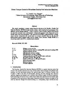
Fig. 2. The diagram of the DFIG direct torque control system. As shown in Fig. 3, the position of the rotor flux is divided into six sectors. There are also 8 voltage vectors which correspond to possible inverter states. These vectors are shown in Fig. 3. There are also six active vectors V1, V2,…, V6 and two zero vectors V0 and V7. (a)
ψs =
Vs
ωs
(15)
The torque of DFIG can be represented as a function of the angle δ between the stator and the rotor fluxes space vectors as follows: Tem = −
L 3 p m ψ s ψ r sin δ 2 σLs Lr
(16)
2 Where σ = 1 − Lm is the leakage coefficient. Ls Lr
Differentiating (16) results in the following equation: d (ψ r sin δ ) dTem 3 L = − p m ψs dt 2 σLs Lr dt
(17)
Therefore, according to (17), we know that the torque control of wound rotor doubly fed machines can be realized through adjusting the rotor flux vector. Where the amplitude of the rotor flux vector can be expressed by: (b)
ψ r = ψ α2r + ψ β2r With: 2 Lm L I αr + m ψ s = L − ψ αr r L Ls s 2 L Lr − m I βr ψ = β r Ls
Fig. 3. Flux space vectors in the rotor reference frame, in motor and generator modes. (a) Motor mode, (b) Generator mode.
(18)
(19)
Furthermore, in the case that the rotor flux ψ r has a circular trajectory (Fig. 4). The electromagnetic torque Tem becomes the function of phase angle δ. Tem increase as δ increase. Conversely, Tem decrease as δ decrease. Therefore, the control of the torque can be realized through adjusting the phase angle δ.
3
Journal of Electrical Engineering www.jee.ro
variable HT what must limit the torque to a value such as Tem* − Tem ≤ ∆Tem .
Fig. 4. Trajectory representation of rotor flux space vector with different voltage vector. A. Hysteresis controllers choice The DTC technique selects the required rotor vector directly from the rotor flux and electromagnetic torque errors, using hysteresis controllers. The flux controller is based on a two level hysteresis comparator with HF hysteresis band, while the torque controller uses a three level hysteresis comparator with HT hysteresis band. At the zero level of this controller, the zero voltage vector is selected in order reduce the torque ripple. Flux vector control: So as to obtain very good dynamic performances, the choice of the hysteresis controller with two levels seems to be the simplest solution and best adapted to the studied control (Fig. 5). Indeed, with this type of controller, one can easily control and maintain the end of the vector flux Ψr in a circular ring. The exit of the comparator represented by the variables HF (= -1 or 1) must indicate if the module of flux must decrease (HF=1) or increase (HF=1) by such kind to always maintain ψ r* − ψ r ≤ ∆ψ r .
Fig. 5. Tow level hysteresis controller. Torque vector control: The hysteresis controller on 3 levels, he makes it possible to control the device in the two directions of rotation that is to say for a positive or negative torque (Fig. 6). The exit of the comparator represented by the
Fig. 6. Three level hysteresis controllers. B. Rotor voltage vector selection The output of both hysteresis controllers that show flux and torque should be increase or decrease. The voltage vectors are selected from the hysteresis controllers’ outputs and the sector where the rotor flux space vector is located. Then the selection of rotor voltage vector is carried out according to Table 1, deduced from Fig. 4: Table 1 Switching table with zero voltage vectors
2 3 4 5
HF HT (330°, 30°) (30°, 90°) (90°, 150°) (150°, 210°) (210°, 270°)
1 V6 V1 V2 V3 V4
1 0 V0 V7 V0 V7 V0
-1 V2 V3 V4 V5 V6
6
(270°, 330°) V5
V7
V1 V4 V0 V2
Hysteresis bands Sector 1 versus Rotor Flux Angle
1 V5 V6 V1 V2 V3
-1 0 V7 V0 V7 V0 V7
-1 V3 V4 V5 V6 V1
As an example, if the rotor flux is located in the first sector, the application of voltages vectors V5 and V6 results in an increase in the torque (HT=1) whereas, the application of vectors V2 and V3 would decrease it (HT=-1). In the other hand, the application of V2 and V6 would increase the rotor flux (HF=1), while V3 and V5 would decrease it (HF=-1). As a generalization it can therefore, be said that if the rotor flux resides in the kth sector, where k = 1, 2, …6, the application of voltage vectors Vk+1 and Vk+2 would decrease the electromagnetic torque, while the vectors Vk-1 and Vk-2 would increase it. Moreover, the application of Vk+2 and Vk-2 would decrease rotor flux, while Vk+1 and Vk-1 would increase it. In this case, for each sector only four active vectors are permitted (Vk-2, Vk-1, Vk+2, Vk+1) and the zero vectors (V0, V7).
4
Journal of Electrical Engineering www.jee.ro
The choice of the zero vectors produces a smaller torque and flux variations compared with the active vectors. Then, the zero vectors are not really needed to keep the torque and flux controlled; however, it is used to reduce the torque and flux ripples at steady state operation. For almost every application of DTC, it is advantageous if the torque and flux ripples are minimized as much as possible [17]. 5. Artificial Neural Network Based Voltage Vector Selection ANN has a very significant role in the field of artificial intelligence. The artificial neurons learn from the data fed to them and keep on decreasing the error during training time and once trained properly, their results are very much same to the results required from them, thus referred to as universal approximators [18]. The most popular neural network used by researchers are the multilayer feed forward neural network trained by the back propagation algorithm [19] .There are different kinds of neural networks classified according to operations they perform or the way of interconnection of neurons. Some approaches use neural networks for parameters estimation of electrical machines in feedback control of their speeds [20]. Here we have used a feed forward neural network to select the voltage vector which replaces the lookup table in the case of C-DTC strategy [12-13-21-22]. In the case presented in this paper the DTC control strategy shown on Table 1 has been implemented. Neural network has been devised having as inputs the torque error, the rotor flux error and the position of the flux sector and as output the rotor voltage space vector to be generate by the inverter [22]. The ANN block then replaces the switching table selector block of Fig. 2; this is illustrated in the Fig. 7.
Levenberg-Marquardt (LVM) back propagation [2324], it updates weights and bias values according to Levenberg-Marquardt optimization algorithm. As soon as the training procedure is over, the neural network gives almost the same output pattern for the same or nearby values of input. This tendency of the neural networks which approximates the output for new input data is the reason for which they are used as intelligent systems. In Matlab command we generate the Simulink block ANN of switching table by “gensim (net35)” given this model shown in Fig. 8.
1
x{1}
1
y {1}
x{1}
y{1}
Neural Network
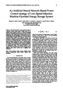
Fig. 8. ANN model switching table. The block ANN content two layer 1 and 2: 1
x p
x{1}
Process Input 1
p{1}
a{1}
Layer 1
a{1}
a{1}
a{2}
Layer 2
a{1}
ay
1
Process Output 1
y{1}
Fig. 9. Neural Network Block. Where the Layer 1 and Layer 2 are show in Fig. 9. 1
TDL
weight
p{1}
Delays 1
IW{1,1} bias
1 netsum
tansig
a{1}
netsum1
purelin
a{2}
b{1} 2
TDL
weight
a{1}
Delays 2
LW{2,1} bias
2
b{2}
Fig. 10. Block Layer 1 and Layer 2. Fig. 7. DTC neural networks controller scheme. The network taken in this study is a 3-35-3 feedforward network with first layer of log sigmoid transfer function, second layer of hyperbolic tangent sigmoid transfer function and third layer of linear transfer function. Training method used was again backpropagation. All the three neural networks were trained to performance 0.01 msec. The back-propagation algorithm is used to train the neural networks. The training function used is
6. Simulation results and comparison Simulations of the proposed direct torque and reactive power control approach are carried out using Matlab/ Simulink. The simulated DFIG is based on the parameters available in the appendix. The simulation results of torque control and rotor flux for both C-DTC strategy and the proposed strategy (ANN-DTC) are presented in Fig. 11 and Fig. 12 respectively
5
Journal of Electrical Engineering www.jee.ro
(a)
(a)
(b)
(b)
(c)
(c)
(d)
(d)
(e)
(e)
(f)
(f)
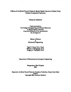
Fig. 11. C-DTC strategy responses.
Fig. 12. ANN-DTC strategy responses.
6
Journal of Electrical Engineering www.jee.ro
The Sampling period of the system is 100µs, the torque and flux references used in the simulation results of the both strategies are (-5kN.m in 0s (generator mode), +5kN.m in 0.4s (motor mode), and again -5kN.m in 0.7s) and 1.1Wb respectively. The machine is driven at supersynchronous speed (1700rpm). All simulation results are show in Fig. 10 and Fig. 11. From top to bottom, the curves are rotor rotating speed, electromagnetic torque, rotor flux, rotor currents, stator currents, and stator current wave form with THD rate. Fig. 10-(a) and Fig .11-(a) show the rotor speed range of operating of the doubly fed induction machine, the machine is running from the subsynchronous speed (1000rpm) until the supersynchronous speed (2000rpm) by crossing the synchronous speed (1500rpm) in 0.55s. The electromagnetic torque follows the reference value quickly in both cases, this is illustrated in Fig. 10-(b) and Fig. 11-(b); it can be seen that the torque’s ripples with ANN-DTC strategy in steady state is significantly reduced (±50N.m) compared to the C-DTC strategy (±150N.m). Fig. 10-(c) and Fig. 11-(c) are showing the rotor flux magnitude responses of C-DTC and ANN-DTC strategy respectively. Note that the rotor flux is maintained constant (1.1Wb) while torque changes, it certify that the decoupled control of rotor flux and torque is achieved. It is also remarkable that the ripple in steady state is reduced in the case of ANN-DTC strategy compared with C-DTC strategy. The rotor flux fluctuating ranges are nearly ±0.12Wb for C-DTC and only ±0.06Wb for ANN-DTC. The simulation results in Fig.10-(d and e) and Fig.11-(d and e) show the response of rotor and stator currents of C-DTC strategy and ANN-DTC strategy respectively. The changeover from subsynchronous to supersynchronous speed crossing the synchronous speed in 0.55s is observed to be smooth without any transients in the rotor current waveform. On the other hand, the FFT analysis (evaluated for five cycles starting at t=0.1s) of the stator current waveform of phase (a) show that the total harmonic distortion (THD) of the stator currents with ANN-DTC [Fig. 11-(f)] is much smaller than that of the stator currents with C-DTC [Fig. 10-(f)]. In the case of CDTC strategy the THD rate is nearly 2.10%, while in the case of ANN-DTC is only 0.51%. Then, we can say that the ANN-DTC strategy has a negligible ripple in stator current and a nearly sinusoidal wave form compared to the C-DTC strategy. 7. Conclusion This paper presents an improved direct torque control strategy for DFIG based wind energy conversion systems. The torque and flux ripples can be reduced significantly and low constant switching
frequency is achieved with the proposed ANN-DTC strategy while the simplicity and robustness of the CDTC is inherited at the most. Simulation results show that the C-DTC strategy presents a fast and good dynamic torque in steady state behavior. However this strategy because of the variable switching frequency presents the drawback to having a high frequency of switching which present a high harmonic distortion of currents, high ripples of electromagnetic torque, and warming-up of the silicon switchers. The proposed ANN-DTC strategy constitutes a viable alternative to the conventional control strategy and it has many features and advantages such as: - It has good performances; - Fast flux and torque responses; - Fixed and low switching frequency; - Reduced torque and current ripples. - It offers sinusoidal line currents. Appendix Table 2 Wind turbine parameters Blade radius, R Number of blades Gearbox ratio, G Moment of inertia, J Viscous friction coefficient, fr Cut-in wind speed Cut-out wind speed Nominal wind speed, v
35.25 m 3 90 1000 Kg.m2 0.0024 N.m.s-1 4 m/s 25 m/s 16 m/s
Table 3 Doubly fed induction generator parameters Rated power, Pn Stator rated voltage, Vs Rated current, In Rated DC-Link voltage UDC Stator rated frequency, f Stator inductance, Ls Rotor inductance, Lr Mutual inductance, Lm Stator resistance, Rs Rotor resistance, Rr Number of pair of poles, p
1.5 MW 398/690 V 1900 A 1200 V 50 Hz 0.0137 H 0.0136 H 0.0135 H 0.012 Ω 0.021 Ω 2
References 1. A. Petersson, “Analysis, modeling and control of doubly fed induction generators for wind turbines”, PhD thesis, Champers University of Technology, Sweden, 2005. 2. I. Takahashi and T. Noguchi, “A new quick-response and high-efficiency control strategy of an induction motor”, IEEE Trans. Ind. Appl., vol. IA-22, no. 5, October 1986, pp. 820-827.
7
Journal of Electrical Engineering www.jee.ro
3. M. Depenbrock, “Direct self control of inverter fed induction machines”, IEEE Trans. Power Electron., vol. 3, 1988, pp. 420-429. 4. F. Blaschke, “A new method for the structural decoupling of AC induction machines”, in Conf. Rec. IFAC, Dussesrdorf, Germany, Oct.1971. 5. T.G. Habetler, F. Profumo, M. Pastorelli, L.M. Tolbert, “Direct torque control of induction machines using space vector modulation”, IEEE Trans. Ind. Appl., vol. 28, no. 5, 1992, pp. 1045-1053. 6. Y.S. Lai, J.H. Chen, “A new approach to direct torque control of induction motor drives for constant inverter switching frequency and torque ripple reduction”, IEEE Trans. Energy Convers., vol. 16, no. 3, 2001, pp. 220-227. 7. D. Casadei, G. Serra, A. Tani, “Improvement of direct torque control performance by using a discrete SVM technique”, in: Proceedings of the 29th IEEE Power Electronics Specialists Conference (PESC), vol. 2, 1998, pp. 997-1003. 8. D. Casadei, G. Serra, A. Tani, “Implementation of a direct control algorithm for induction motors based on discrete space vector modulation”, IEEE Trans. Power Electron., vol. 15, no. 4, 2000, pp. 769-777. 9. Y. Xia, W. Oghanna, “Fuzzy direct torque control of induction motor with stator flux estimation compensation”, in: Proceedings of the 23rd International Conference on Industrial Electronics, Control and Instrumentation (IECON), vol. 2, 1997, pp. 505-510. 10. F. Bacha, R. Dhifaoui, H. Buyse, “Real-time implementation of direct torque control of an induction machine by fuzzy logic controller”, in: Proceedings of the International Conference on Electrical Machines and Systems (ICEMS), vol. 2, 2001, pp. 1244-1249. 11. S. Mir, M.E. Elbuluk, D.S. Zinger, “PI and fuzzy estimators for tuning the stator resistance in direct torque control of induction machines”, IEEE Trans. Power Electron., vol. 13, no. 2, 1998, pp. 279-287. 12. Luis A. Cabrera, Malik E. Elbuluk, and Donald S.Zinger, “Learning Techniques to Train Neural Networks as a State Selector for Inverter-Fed Induction Machines Using Direct Torque Control”, IEEE-PE, Vol. 12, No. 5, Sept. 1997, pp 788-799. 13. X. Wu and L. Huang, “Direct torque control of three level inverter using neural networks as switching vector selector”, Industry Applications Conference. Thirty-Sixth IAS Annual Meeting. Conference Record of the IEEE, vol. 2, 2001, pp. 939-944. 14. Y.V. Siva Reddy, M. Vijayakumar, and T. Brahmananda Reddy, “Direct torque control of induction motor using sophisticated lookup tables based on neural network”, AIML Journal, vol.7, issue 1, June 2007. 15. B. Hopfensperger, D. J. Atkinson, and R. Lakin, “Stator-flux-oriented control of a doubly fed induction machine with and without position encoder”, IEE Proc.-Electr. Power Applications, vol. 147, no. 4, July 2000, pp. 241-250. 16. G. Abad and all, “Doubly fed induction machine: modeling and control for wind energy generation”, Institute of Electrical and Electronic Engineers, Inc. Published by John Wiley & Sons, Inc, 2011.
17. G. Abad, “Predictive direct control techniques of the doubly fed induction machine for wind energy generation applications”, PhD thesis, Mondragon University, Arrasate, Spain, 2008. 18. Hornik, M. Stinchcombe and H. White, “Multilayer feed forward networks are universal approximators”, Neural Networks, vol. 2, 1989, pp. 359-366. 19. P. Werbos, “Beyond regression: new tools for prediction and analysis in the behavioral sciences”, PhD thesis, Cambridge, MA: Harvard University Committee on Applied Mathematics, 1974. 20. D. Kukolj, F. Kulic and E. Levi, “Design of speed controller for sensorless electric drives based on ai techniques: a comparative study”, Artificial Intelligence in Engineering, vol. 14, 2000, pp. 165174. 21. R. Kumar, R. A. Gupta, S.V. Bhangale, and H. Gothwal, “Artificial neural network based direct torque control of induction motor drives”, IETECH Journal of Electrical Analysis, vol. 2, no. 3, IETECH Publications 2008, pp.159-165. 22. Cirrincione, M.C. Lu, and M. Pucci, “Direct torque control of induction motors by use of the GMR neural network”, International Joint Conference on Neural Networks, vol. 3, 2003, pp. 2106-2111. 23. J.J. Moré, “The Levenberg-Marquardt Algorithm: Implementation and Theory”, Numerical Analysis, ed. G. A. Watson, Lecture Notes in Mathematics 630, 1977, Springer Verlag, pp.105-116. 24. M.T. Hagan, M. Menhaj, “Training feedforward networks with the Marquardt algorithm”, IEEE Trans, Neural Networks, vol. 5, no. 6, 1994, pp .989993.
8