Modern Applied Science
Vol. 2, No. 6
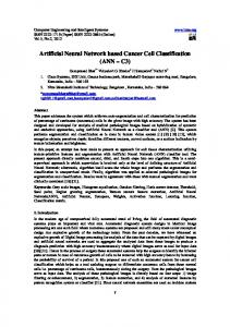
Artificial Neural Network Based Rotor Position Estimation for Switched Reluctance Motor L.Jessi Sahaya Shanthi(Corresponding Author) Department of Electrical and Electronics Engineering Thiagarajar College of Engineering, Madurai-625 015, India E-mail:
[email protected] R.Arumugam Department of Electrical and Electronics Engineering SSN College of Engineering, Chennai, India Y.K.Taly Head,Control Instrumentation Division of Bhabha Atomic Research Centre (BARC),Mumbai, India S.B.Nandha Kumar Department of Electrical and Electronics Engineering Thiagarajar College of Engineering, Madurai-625 015, India Abstract
Switched Reluctance Motor (SRM) is becoming popular as a variable speed industrial drive. But the requirement of position sensor to synchronize the rotor position with phase currents makes the SRM drive circuit complex and unreliable. With the advent of high speed digital signal processors, it is possible to implement algorithms to estimate the rotor position based on the electrical signals in motor windings. In addition to this, the latest graphical user interface software aids to reduce the time for the development of control algorithms. This paper presents the simulation study of an artificial neural network(ANN) based algorithm for rotor position estimation from phase voltage and current of a four phase SRM using VISSIM version 6.0B software. Based on the simulation results, a particular artificial neural network (ANN) is selected and checked for real time implementation. Keywords: Switched reluctance motor, Rotor position estimation, Artificial neural network, VISSIM version 6.0B 1. Introduction
The Switched Reluctance Motor (SRM) drives have been receiving attention as variable speed industrial drives due to its simple construction, low manufacturing cost, fault tolerance, absence of magnets, rotor conductors and brushes, reduced maintenance requirements, rugged behavior, and large torque output over very wide speed range. The SRM drives can also deliver servo-drive performance equivalent to dc brushed motors. During the twenty years, the study of Switched Reluctance Motor (SRM) has made rapid progress. It has many fine features, such as simple and robust structure with no windings on the rotor, maximum operating speed and the ability of operating at high rotor temperatures.The simple power electronic converter requirement, the fault tolerant capability and the high torque per inertia ratio are the very specific advantages of SRM drives. The primary disadvantages of SRM drives are the rotor position sensing requirements and the higher torque ripple compared to other machines [1]-[10]. In aerospace applications, the design engineers of motor drive system for the fuel delivery system are concentrating on SRM drives because of the basic need of designing a compact and minimum weight system [9]. However, rotor position sensing plays a vital role in SRM drives, as commutation signals for the converter are derived from the position sensor signals. The position sensor unit adds to the system cost and dimensions and impair the drive reliability. To design a reliable and compact controller for SRM drives, the position sensor unit should be eliminated. Implementing the sensorless scheme using the fast acting digital signal processors makes the overall system reliable, compact and accurate [10]. 148
Modern Applied Science
November, 2008
2. Rotor Position Estimation Methods
Several sensorless rotor position estimation methods have been patented and published for sensorless control of SRM drives. All of these methods use the instantaneous phase inductance variation information in some way to detect the rotor position indirectly. As the flux linkage - rotor position - current characteristics vary significantly between the aligned and unaligned positions of the doubly salient stator and rotor poles, it is possible to estimate the rotor position indirectly in SRM drives [5] - [8]. The methods can be broadly classified into two categories: (i)Non-intrusive methods, where position information is obtained from terminal measurements of voltages and currents and associated computations, and (ii) Intrusive (Active probing) methods, where low level high-frequency signals are injected into an idle phase to determine the position dependent, unsaturated phase inductance characteristics. The Non-intrusive methods rely on the machine characteristics for estimating the rotor position. The following are the various Non-intrusive methods: (i) The model based estimator technique (ii) The flux linkage/current method and (iii) The mutual voltage method [7]. For these methods the terminal measurements of phase voltage or mutual voltage and current are used as inputs for an estimator to obtain the rotor position. In model based estimator technique, the feedback gains of the observer are dependent on the input variables, i.e. phase current and voltage measurements. The rotor position is obtained as an estimated state variable from the observer [6]. In the flux linkage -current method, the terminal measurements are applied in the following equation to obtain the phase flux linkage,
ψ = ³ (v − R ∗ i ) ⋅ dt
(1)
Where Ψ is phase winding flux linkage, v is voltage across the phase winding, R is phase winding The various sensorless rotor position estimation methods suggested in the resistance and i is phase current. literature have their own merits and demerits depending on their principle of operation. Ideally, it is desirable to have a sensorless scheme, which uses only terminal measurements and does not require additional hardware [7]. Recently a number of papers have been published in the area of artificial neural network for motion control. Application of artificial neural network for position estimation in SRM drives is also studied by many researchers. In an earlier ANN based non intrusive rotor position estimation work, the estimation error is usually bounded on [ − 5 ° , + 5 ° ] [1].And the method deserves consideration as a candidate for integration in to practical SRM drive systems. Based on the works in [1] and [2] the simulation study of an artificial neural network(ANN) based algorithm for rotor position estimation from phase voltage and current of a four phase SRM using VISSIM version 6.0B software is done and the results are shown. In this paper, the nonlinear characteristics of SRM are discussed. Different architectures of artificial neural network are tuned for phase flux linkage and phase current waveforms as input and rotor position as output. The different ANN structures are trained for the same data. The trained ANN structure with minimum error is verified experimentally. 3. The Nonlinearised dynamic model of SRM
The switched reluctance machine is a doubly salient machine with unequal number of rotor and stator poles.Windings of diametrically opposite stator poles are connected in series to form one phase of the machine. As the switched reluctance machine is a doubly salient machine, its electromagnetism characteristic has high saturation effect [2]. This makes the model highly nonlinear and the simulation work includes more nonlinear functions. The SRM’s voltage balance equation is, Vk = Rk * i k +
d ψ k ( ik , θ ) dt
Where Vk is the applied voltage to the kth phase, Rk is the phase resistance, the kth phase and ψk (ik ,θ ) is the flux linkage at the kth phase.
(2)
ik is the stator current passing through
The SRM’s mechanical equation is Te = J
d 2θ dθ +D + TL dt dt 2
(3)
Where Te is the total electro mechanical torque produced, J is the moment of inertia of the drive, D is the viscous friction coefficient and TL is the load torque. Then,
ψ k = ψ k (i k , θ ) vk = Rk ik +
∂ȥk dik ∂ȥk dș . . + ∂ik dt ∂ș dt
(4) (5)
149
Modern Applied Science
Vol. 2, No. 6 ∂Lk · dik ∂Lk dθ § = Rk .ik + ¨ Lk + ik + ik ¸ ∂ i dt ∂θ dt k © ¹
∂Lk ∂Lk · dik § .ω + ik = Rk .ik + ¨ Lk + ik ¸ ∂θ ∂ik ¹ dt ©
(6)
From equation no.(6),ik can be expressed
ik = ³
dik dt
Vk − Rkik − ikω . .dt = ³
∂Lk ∂θ
∂L º ª L +i . «¬ ∂i » ¼
(7)
dt
k
k
k
k
In the above equations (6) and (7) inductance related terms are substituted in terms of Lk=L0 + P(ș) .Q(ik)
(8)
P(ș) = a0+ ar sin(brș - Ɏr),
(9)
Where n r=1 Q(i) =[(1-c1ik )/ c2] sin( ik-c3)
(10)
The wave shaping constants ar, br and Ɏr are chosen according to the inductance profile of an 8/6 motor with respect to rotor position at constant current. The constants c1, c2 and c3 are chosen according to the nonlinear relation of phase inductance with current. And L0 is the minimum unaligned inductance which is dependent on rotor pole height. Torque can be expressed as, ∂wk ∂θ
Tek =
ik = Cons tan t
Where wk is the magnetic co-energy of winding. ik
=
∂ ³ψ k (θ , i k ) di k 0
∂θ
i1 ∂ ³ Lk (θ , ik ).ik.dik Tek = 0 ∂θ
(11)
4
Te = ¦ Tek k =1
Hence torque output can also be got in terms of inductance as in equation (11). Figure.1 VISSIM based model of SRM and flux estimator The four phase, 8/6 pole SRM is modeled based on the equations (1) – (11). The VISSIM based SRM model and its output waveforms are shown in Fig.1.The individual phase models are grouped to get the over all model. The flux linkage estimation algorithm is simulated for the four phases. The simulation study enhances the analysis of flux linkage estimation for different excitation patterns. The results shown are for turn on degree of 7.5 degree mechanical with respect to unaligned position of phase A and turn off degree 0f 22.5 degree mechanical. 4. Simulation model of ANN based rotor position estimator
The Vissim block diagram for ANN based rotor position estimation is shown in Fig.2. The flux linkage and current values for four phases are collected in the flux-current.dat file for one electrical cycle. It is equivalent to 60 degree mechanical. The flux linkage- current - rotor position for the four phases are the ANN training data.The various ANN structures are trained for the same data. By trial and error method, it is found that the ANN with one hidden layer and twenty neurons per layer provided minimum error. The neural network setup in VISSIM is shown in Fig.3 and Fig.4.The learning method used is back propagation with momentum.The learn rate selected is 0.8 and momentum selected is 0.8.The various ANN structures are run in parallal and errors are compared. Figure.2 ANN based rotor position estimation using VISSIM 150
Modern Applied Science
November, 2008
5. Simulation Results
The different ANN structures are trained for the same set of flux linkage-current-rotor position data. The different structures are the following, Case 1: Number of hidden layers=2, Number of neurons per layer = 10, Method=Back Propagation, Learn rate=0.5 and weight=0.5. Case 2: Number of hidden layers=1, Number of neurons per layer = 30, Method=Back Propagation, Learn rate=0.5 and weight=0.5. Case 3: Number of hidden layers=1, Number of neurons per layer = 20, Method=Back Propagation with momentum, Momentum=0.7, Learn rate=0.7 and weight=0.5. Case 4: Number of hidden layers=1, Number of neurons per layer = 20, Method=Back Propagation with momentum, Momentum=0.5, Learn rate=0.5 and weight=0.8. Case 5: Number of hidden layers=1, Number of neurons per layer = 20, Method=Back Propagation with momentum, Momentum=0.8, Learn rate=0.8 and weight=0.8. Figure.3 Neural net setup information for Case 4 Figure.4 Neural net setup information for case 5 From the simulation results, ANN structure with case 5 is the best for training the flux linkage-current-rotor position data. The position estimation error using this ANN structure is bounded on [ − 2 . 4 ° , + 1 . 2 ° ] mechanical. In Fig.5 the rotor position estimation results for two different ANNs (case 4 and case 5) are shown. In Fig.6 the rotor position estimation error results for two different ANNs (case 4 and case 5) are shown for comparison. From the SRM model designed, the flux linkage and current of four phases are studied and verified for different commutation angles. The results shown are for turn on degree of 7.5 degree mechanical with respect to unaligned position of phase A and turn off degree of 22.5 degree mechanical. The model has simulation step time limitation. The maximum value of simulation step time is 0.001seconds. Figure.5 Rotor Position vs Time for two different ANNs (case 4 and case 5) Figure.6 Error vs Time for two different ANNs (case 4 and case 5) 6. Experimental Setup and results
The following Fig.7 shows the experimental setup of power circuits to drive the 8/6 SRM and Fig.8 shows the reflective type position sensor setup used to produce the commutation signals for the control of SRM with position sensor. The online information of flux linkage-current-position is collected through Vissim-GUI working environment with position sensor setup. The Texas Instruments Digital Signal Processor TMS320F2812 is used with Vissim-GUI working environment. The hall effect voltage and current sensors are used with signal conditioner circuits to feed the phase voltage-current information to ADC of DSP. Based on the values of phase voltage-current data, the phase flux linkages are calculated based on equation (1). The flux linkage-current-position data is collected in .dat files. The different neural networks can be trained with the collected data through .dat files. The errors can be compared. In this paper, comparision between only two ANNs are prouced. The network with minimum error can be selected for real time application. The ANN with minimum error is checked for real time application. It is working for only low speeds. Fig.7 Experimental setup of 8/6 SRM Converter circuits(left) and voltage-current sensors setup(right) Fig.8 Reflective type sensors used to produce commutation signals 7. Conclusion
The results obtained from the VISSIM based ANN rotor position estimator are compared with the actual rotor position. The minimum estimation error is bounded on [ − 2 . 4 ° , + 1 . 2 ° ] for the ANN structure with case 5.The simulation work is very much useful in the analysis of flux linkage – current for different turn on, turn off angles and to select the structure of ANN. Using the ramp generator block in VISSIM the different commutation signals can be generated. The reset integrator block is used to evaluate flux linkage from phase voltage and phase currents. The flux linkage - current - rotor position data is tuned in the neural network. This paper provides enough research material for analyzing the nonlinearised model and to estimate rotor position with various ANN structures using VISSIM. The structure with minimum error can be selected for real time application. The results obtained are experimentally checked only for low speed position sensorless control of SRM. Acknowledgement
With out the blessings of Almighty, the support of management and staff members of Thiagarajar College of 151
Modern Applied Science
Vol. 2, No. 6
Engineering this research work is not possible. The research work is supported by Bhabha Atomic Research Centre, Mumbai, India. The motor used in this research is from Bhabha Atomic Research Centre, Mumbai, India. The encouragement from Broad of Research in Nuclear Sciences (BRNS), Department of Atomic Energy, India is gratefully acknowledged. References
Arthur V.Radun, “High Power Density Switched Reluctance Motor Drive for Aerospace Applications”, IEEE trans. Ind. Applicat., vol.28,No.1,January/February 1992. Erkan Mese and David A.Torrey, “An Approach for Sensorless Position Estimation for Switched Reluctance Motors Using Artificial Neural Networks”, IEEE Transactions on Power Electronics, vol.17, no.1, January 2002. Fabio Filicori, Corrado Guarino LoBianco, Alberto Tonielli, “Modeling and Control strategies for a Variable Reluctance Direct-Drive Motor”, IEEE Transactions on Industrial Electronics, Vol. 40, No.1, February 1993. G.Suresh, B.Fahimi, K.M.Rahman, M.Ehsani “Analysis of Amplitude Modulation Methods for Sensorless SRM Drives”, IEEE PESC Conference Records,1998. G.Suresh, B.Fahimi, K.M.Rahman, M.Ehsani “Inductance Based Position Encoding IEEE Proc. Pp.832-837Apr 1999.
for sensorless SRM drives”
Khwaja M.Rahman, Steven E.Schulz, “High Performance Fully Digital Switched Reluctance Motor Controller for Vehicle Propulsion”, IEEE Trans. Ind. Applicat., vol.38, No.4, July/August 2002. MStiebler andke Liu, “An Analytical Model of Switched Reluctance Machines” IEEE Transactions on Energy Conversion, Vol.14, December 1999. Tom Perl, Iqbal Husain, Malik Elbuluk, “Design Trends and Trade offs for Sensorless Operation of Switched Reluctance Motor Drives”, IEEE Conference Records, 1995. Wenzhe Lu, AliKeyhani, “Sensorless Control of Switched ReluctanceMotors Using Sliding Mode Observers”, IEEE Proc.pp.69- 72 2001. YulongCui, XiangWang, Chaoying Liu, Jiaomin Liu, “The Simulation Study Of Switched Reluctance Motor’s Non Linearized Model”, Proc. of Second International Conference On Machine Learning And Cybernetics Page No 2720-2725, November 2003.
Figure 1. VISSIM based model of SRM and flux estimator
152
Modern Applied Science
November, 2008
Figure 2. ANN based rotor position estimation using VISSIM
Figure 3. Neural net setup information for Case 4
Figure 4. Neural net setup information for case 5 153
Vol. 2, No. 6
Modern Applied Science
Figure 5. Rotor Position vs Time for two different ANNs (case 4 and case 5)
Figure 6. Error vs Time for two different ANNs (case 4 and case 5)
Figure 7. Experimental setup of 8/6 SRM Converter circuits(left) and voltage-current sensors setup(right) 154
Modern Applied Science
November, 2008
Figure 8. Reflective type sensors used to produce commutation signals
155