Artificial Neural Network Modelling of ADS designed Double Pole Double Throw Switch 1
Shubhankar Majumdar1, Mohd. Zuhair2, and Dhrubes Biswas3
Advanced Technology Development Centre, IIT Kharagpur, Kharagpur, India Rajendra Mishra School of Engineering Entrepreneurship, IIT Kharagpur, Kharagpur, India 3 Department Dept. of Electronics and Electrical Communication Engineering, IIT Kharagpur, Kharagpur, India Email:
[email protected],
[email protected],
[email protected] 2
Abstract - An alternative approach for designing a DPDT switch and characterizing it with the help of ANN modelling is presented in this work. ANN is one of the options which can be implemented to model the output parameters obtained from the designed switch. As, it does not require any detailed physical models, only a few training points are required to accurately model the standards. In this work, the DPDT switch circuit has been designed using ADS through UMS 0.15 µm pHEMT process design kit. Neural network training has been done using Levenberg-Marqaurdt back propagation algorithm employed in the ANN toolbox of MATLAB software. The outcome of simulated results in an ADS designed switch indicates an isolation of -31 to -17 dB, an insertion loss of -1.15 to -0.8 dB, a noise figure of 0.4 to 0.38 and port return loss of 8.44 to -14.36 dB for a frequency level of 1 to 5 GHz. All the results obtained from ADS simulation have been validated using ANN modelling, and it shows a close agreement with a mean squared error of about 10-8. Index Terms - DPDT Switch; Artificial Neural Network; Isolation; Insertion Loss; Noise Figure; Port Return Loss.
I. INTRODUCTION DPDT switch consist of two SPDT switches, which can control two separate circuits, but are always switched together by a single actuator. It has six terminals and it operates in three different ways, they are Open (O), Closed (C), and Double Throw (DT) condition. When the switch is activated contacts control two circuits: one open contact and other closed contact with a common terminal [1]. Thus, the important parameter of this DPDT switch is isolation (when the control signal is off), insertion loss (IL) (when the control signal is on), port return loss (PRL) (reflection from the ports) and noise figure (NF). So, for proper functioning of the DPDT switch these parameters should be high [2, 3]. Thus, functioning and designing of DPDT switch is critical and therefore the research is focused on accurate modeling of DPDT switch. The modelling implemented in the area of circuits are (i) Physical or “physics-based” device models which are calibrated using data; (ii) Measurement-based models can be analytical models or Black box models or table-based models and (iii) ANN Models. Out of these ANN modelling techniques aim to characterize the microwave device efficiently and accurately [4]. These are accurate as "fine" model and as fast as "coarse" model. Fine model has higher accuracy but it is not feasible as the simulators needs long
978-1-4799-4006-6/14/$31.00 ©2014 IEEE
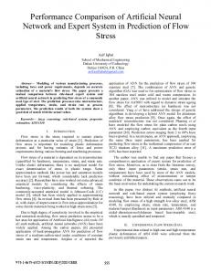
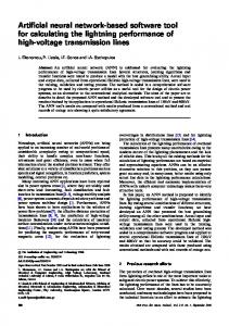
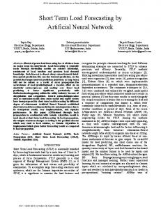
run. Coarse models are mathematical curve fitting techniques using data obtained from measurements and they are used to compute S-parameters, those can be integrated in simulators. Some advantages of ANN modeling are; (i) ANN do not require detailed physical models; (ii) also are more compact than large measurement data files; (iii) requires only few training points to accurately model the standards; and (iv) is more accurate than direct calibrations when limited calibration data are available[5]. ANN techniques have been used for a microwave application circuit design such as power amplifiers [6], [7]. ANN has also been used in calibration [8] and measurements [8, 9]. II. ANN MODELLING OF CIRCUIT A. Circuit Design The circuit design is done in the Agilent’s Advanced Design System (ADS) tool. The transistors and passive components used in the circuit is taken from United Monolithic Semiconductor (UMS) Process Development Kit (PDK) named PPH15. By the help of simulation in ADS Sparameters of the circuit are extracted. There are two input ports (port1 and port2), two output ports (port3 and port4) and two ports for control signals (which controls the functioning of the DPDT switch) in the circuit. The inputports are terminated through 50Ω load. B. Neural Network Structures Different ANN structures can be constructed by using different types of neurons and their different interconnections [10, 11]. A three layer architecture (1-15-6) shown in fig.1 frequency (Hz) is given as input to ANN which computes it internally using neurons and gives output. The outputs are (i) IL S(2,3) and S(1,4) (ii) IL S(1,3) and S(2,4) (iii) Isolation S(1,2) (iv) Isolation S(3,4) (v) PRL S(1,1), S(2,2), S(3,3) and S(4,4) (vi) NF.
Fig.1: Neural Network Architecture
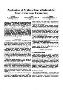
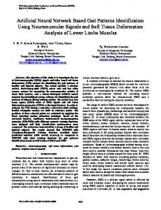
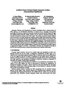
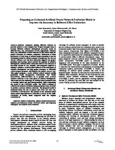
The training algorithm used for ANN is the LevenbergMarquardt (TRAINLM) III. RESULTS AND DISCUSSION A. Circuit analysis The circuit parameters which are calculated by ADS are shown in black line in the plot and red line corresponds to the ANN modeled plot. The parameters of DPDT switch like IL, PRL, NF, and isolation are shown in the fig.2.
IV. CONCLUSION The developed ANN model is used in designing of pHEMT DPDT switch for 1-5GHz operating frequency range. Essential parameters of switch such as IL (1.15 to 0.8), isolation (-31 to -17 dB), NF (0.4 to 0.38dB) and PRL (-8.44 to -14.36) are modeled by the help of multilayer feedforward neural network method. The results are verified by comparing them with ADS simulation results and which shows a close proximity with 2.5803e-8mse. Thus, it can be concluded that it is time consuming to complete a full-wave simulation during DPDT switch design in ADS but on other hand, ANN leads to an accurate, robust, easy and fast modeling technique for DPDT switch. Hence, ANN model can help to speed up the production of other RF module also ACKNOWLEDGMENT This work is done in the ATDC lab of IIT Kharagpur, W.B, India. Authors are thankful to the UMS Company for providing the process development kit (PPH15). REFERENCES [1]
Fig.2: Graph of IL between Antenna (port1) and output (port4) and Antenna (port2) and output (port3), IL between Antenna (port2) and output (port4) and Antenna (port1) and output (port3), Isolation between output (port3) and output (port4), Isolation between Antenna (port1) and Antenna (port2), PRL, NF.
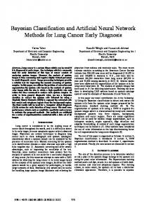
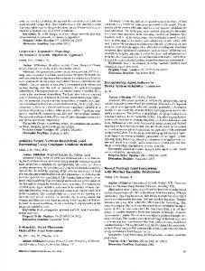
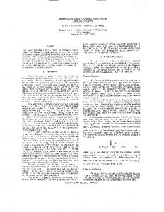
B. Neural Network Results The training of ANN has been done by using 200 data points and the comparison of the results has been shown in fig.2 which is similar to the output of simulated result of DPDT switch. Deviation shown in fig.2 depicts marginal deviation from actual output of ANN and the overall performance of neural network is depicted in fig.3. The best validation performance occurred at epochs-1000 with a mean square error (mse) of 2.5803e-8.
Fig. 3: Best Validation Performance of neural network is 2.5803e-8 at epoch 1000.
Analog Device, “0.4 Ω CMOS, Dual DPDT Switch in WLCSP/LFCSP/TSSOP Packages,” ADG888 datasheet, Jul 2005 [Revised Dec. 2006]. [2] M. J. Schindler, T. E. Kazior, "A high power 2-18 GHz T/R switch," Microwave and Millimeter-Wave Monolithic Circuits Symposium, 1990. Digest of Papers., IEEE 1990, vol., no., pp.119,122, 7-8 May 1990. doi: 10.1109/MCS.1990.110953. [3] S. Tamura, Y. Anda, M. Ishida, Y. Uemoto, T. Ueda, T. Tanaka, D.Ueda, "Recent Advances in GaN Power Switching Devices," Compound Semiconductor Integrated Circuit Symposium (CSICS), 2010 IEEE, vol., no., pp.1,4, 3-6 Oct. 2010. doi: 10.1109/CSICS.2010.5619659 [4] Humayun Kabir, Lei Zhang, Ming Yu, Peter H. Aaen, John Wood, and Qi-Jun Zhang, “Smart Modeling of Microwave Devices”, IEEE Microwave Magazine, pp.105-118,2010. [5] S. Haykin, Neural Networks - A Comprehensive Foundation. NJ, USA: Prentice-Hall, 1999. [6] Fang. Yonghua, M. C E Yagoub, Fang Wang, Qi-Jun Zhang, "A new macromodeling approach for nonlinear microwave circuits based on recurrent neural networks," Microwave Theory and Techniques, IEEE Transactions on, vol.48, no.12, pp.2335,2344, Dec 2000. doi: 10.1109/22.898982. [7] Xu Jianjun, M. C E Yagoub, Ding Runtao, Qi-Jun Zhang, "Neuralbased dynamic modeling of nonlinear microwave circuits," Microwave Theory and Techniques, IEEE Transactions on, vol.50, no.12, pp.2769,2780, Dec 2002. doi: 10.1109/TMTT.2002.805192. [8] Jeffrey A. Jargon, K. C. Gupta, Donald C. DeGroot, “Applications of Artificial Neural Networks to RF and Microwave Measurements,” John Wiley & Sons, Inc, 2002. [9] P. M. Watson, K. C. Gupta, and R. L. Mahajan, “Applications of Knowledge-Based Artificial Neural Network Modeling to Microwave Components," International Journal of RF and Microwave ComputerAided Engineering, vol. 9, no. 3, pp. 254-260, March, 1999. [10] Q.J. Zhangand, Lei Zhang,“ANN/DNN-Based Behavioral Modeling of RF/Microwave Components and Circuits” in Scientific Computing in Electrical Engineering (SCEE) 2008 Mathematics in Industry. Janne Roos, R.J. Luis Costa, Ed. Springer Berlin Heidelberg, 2010, pp.215-224. [11] M. Vai and S. Prasad, “Neural Networks in Microwave Circuit Design -Beyond Black Box Models," International Journal of RF and Microwave Computer-Aided Engineering, vol. 9, no. 3, pp. 187-197, May 1999.