Mar 13, 2014 - IT] 13 Mar 2014. ASPECTS OF FAVORABLE PROPAGATION IN MASSIVE MIMO. Hien Quoc Ngoâ, Erik G. Larssonâ, Thomas L. Marzettaâ .
ASPECTS OF FAVORABLE PROPAGATION IN MASSIVE MIMO Hien Quoc Ngo∗ , Erik G. Larsson∗, Thomas L. Marzetta† ∗
Department of Electrical Engineering (ISY), Link¨oping University, 581 83 Link¨oping, Sweden † Bell Laboratories, Alcatel-Lucent Murray Hill, NJ 07974, USA
arXiv:1403.3461v1 [cs.IT] 13 Mar 2014
ABSTRACT Favorable propagation, defined as mutual orthogonality among the vector-valued channels to the terminals, is one of the key properties of the radio channel that is exploited in Massive MIMO. However, there has been little work that studies this topic in detail. In this paper, we first show that favorable propagation offers the most desirable scenario in terms of maximizing the sum-capacity. One useful proxy for whether propagation is favorable or not is the channel condition number. However, this proxy is not good for the case where the norms of the channel vectors may not be equal. For this case, to evaluate how favorable the propagation offered by the channel is, we propose a “distance from favorable propagation” measure, which is the gap between the sumcapacity and the maximum capacity obtained under favorable propagation. Secondly, we examine how favorable the channels can be for two extreme scenarios: i.i.d. Rayleigh fading and uniform random line-of-sight (UR-LoS). Both environments offer (nearly) favorable propagation. Furthermore, to analyze the UR-LoS model, we propose an urns-and-balls model. This model is simple and explains the singular value spread characteristic of the UR-LoS model well. 1. INTRODUCTION Recently, there has been a great deal of interest in massive multiple-input multiple-output (MIMO) systems where a base station equipped with a few hundred antennas simultaneously serves several tens of terminals [1–3]. Such systems can deliver all the attractive benefits of traditional MIMO, but at a much larger scale. More precisely, massive MIMO systems can provide high throughput, communication reliability, and high power efficiency with linear processing [4]. One of the key assumptions exploited by massive MIMO is that the channel vectors between the base station and the terminals should be nearly orthogonal. This is called favorable propagation. With favorable propagation, linear processing can achieve optimal performance. More explicitly, on the uplink, with a simple linear detector such as the matched filter, noise and interference can be canceled out. On the downlink, with linear beamforming techniques, the base station The work of H. Q. Ngo and E. G. Larsson was supported in part by the Swedish Research Council (VR), the Swedish Foundation for Strategic Research (SSF), and ELLIIT.
can simultaneously beamform multiple data streams to multiple terminals without causing mutual interference. Favorable propagation of massive MIMO was discussed in the papers [4,5]. There, the condition number of the channel matrix was used as a proxy to evaluate how favorable the channel is. These papers only considered the case that the channels are i.i.d. Rayleigh fading. However, in practice, owing to the fact that the terminals have different locations, the norms of the channels are not identical. As we will see here, in this case, the condition number is not a good proxy for whether or not we have favorable propagation. In this paper, we investigate the favorable propagation condition of different channels. We first show that under favorable propagation, we maximize the sum-capacity under a power constraint. When the channel vectors are i.i.d., the singular value spread is a useful proxy to evaluate how favorable the propagation environment is. However, when the channel vectors have different norms, this is not so. We also ask whether or not practical scenarios will lead to favorable propagation. To this end, we consider two extreme scenarios: i.i.d. Rayleigh fading and uniform random line-of-sight (UR-LoS). We show that both scenarios offer substantially favorable propagation. We also propose a simple urns-and-balls model to analyze the UR-LoS case. For the sake of the argument, we will consider the uplink of a single-cell system. 2. SINGLE-CELL SYSTEM MODEL Consider the uplink of a single-cell system where K singleantenna terminals independently and simultaneously transmit data to the base station. The base station has M antennas and all K terminals share the same time-frequency resource. If the K terminals simultaneously transmit the K symbols � � x1 , . . . , xK , where E |xk |2 = 1, then the M × 1 received vector at the base station is K
y=
√ √ X ρ g k xk + w = ρGx + w,
(1)
k=1
where x = [x1 , . . . , xK ]T , G = [g 1 , . . . , g K ], g k ∈ CM×1 is the channel vector between the base station and the kth terminal, and w is a noise vector. We assume that the elements of w are i.i.d. CN (0, 1) RVs. With this assumption, ρ has the interpretation of normalized “transmit” signal-to-noise ratio (SNR). The channel vector g k incorporates the effects of
large-scale fading and small-scale fading. More precisely, the mth element of g k is modeled as: p gkm = βk hm k = 1, . . . , K, m = 1, . . . , M, (2) k , hm k
where is the small-scale fading and βk represents the large-scale fading which depends on k but not on m. 3. PRELIMINARIES OF FAVORABLE PROPAGATION In favorable propagation, we can obtain optimal performance with simple linear processing techniques. To have favorable propagation, the channel vectors {g k }, k = 1, . . . , K, should be pairwisely orthogonal. More precisely, we say that the channel offers favorable propagation if � 0, i, j = 1, . . . , K, i 6= j H gi gj = (3) kg k k2 6= 0, k = 1, . . . , K. In practice, the condition (3) will never be exactly satisfied, but (3) can be approximately achieved. For this case, we say that the channel offers approximately favorable propagation. Also, under some assumptions on the propagation environment, when M grows large and k 6= j, it holds that 1 H g g →0, M k j
M → ∞.
(4)
For this case, we say that the channel offers asymptotically favorable propagation. The favorable propagation condition (3) does not offer only the optimal performance with linear processing but also represents the most desirable scenario from the perspective of maximizing the information rate. See the following section. 3.1. Favorable Propagation and Capacity Consider the system model (1). We assume that the base station knows the channel G. The sum-capacity is given by C = log2 I + ρGH G . (5)
Next, we will show that, subject to a constraint on G, under favorable propagation conditions (3), C achieves its largest 2 possible value. Firstly, we assume {kg k k } are given. For this case, by using the Hadamard inequality, we have ! K Y H H C = log2 I + ρG G ≤ log2 [I + ρG G]k,k k=1
=
K X
k=1
K � � � X � log2 1+ρkg k k2 . (6) log2 [I +ρGH G]k,k = k=1
We can see that the equality of (6) holds if and only if GH G is diagonal, so that (3) is satisfied. This means that, given 2 a constraint on {kg k k }, the channel propagation with the condition (3) provides the maximum sum-capacity.
Secondly, we consider a more relaxed constraint on the 2 2 channel G: constraint kGkF instead of {kg k k }. From (6), by using Jensen’s inequality, we get K � � � � 1X 2 2 log2 1 + ρkg k k log2 1 + ρkg k k = K · K k=1 k=1 ! K � � X ρ ρ ≤Klog2 1+ kg k k2 = Klog2 1 + kGk2F , (7) K K
C≤
K X
k=1
where the equality in the first step holds when (3) satisfied, 2 and the equality in the second step holds when all kg k k are equal. So, for this case, C is maximized if (3) holds and {g k } have the same norm. The constraint on G that results in (7) is more relaxed than the constraint on G that results in (6), but the bound in (7) is only tight if all {g k } have the same norm. 3.2. Measures of Favorable Propagation Clearly, to check whether the channel can offer favorable propagation or not, we can check directly the condition (3) or (4). However, to do this, we have to check all (K − 1)K/2 possible pairs. This has computational complexity. Other simple methods to measure whether the channel offers favorable propagation is to consider the condition number, or the distance from favorable propagation (to be defined shortly). These measures will be discussed in more detail in the following subsections. 3.2.1. Condition Number Under the favorable propagation condition (3), we have 2
2
GH G = Diag{kg 1 k , · · ·, kg K k }.
(8)
We can see that if {g k } have the same norm, the condition number of the Gramian matrix GH G is equal to 1: σmax /σmin = 1,
(9)
where σmax and σmin are the maximal and minimal singular values of GH G. Similarly, if the channel offers asymptotically favorable propagation, then we have GH G → D,
M → ∞,
(10)
where D is a diagonal matrix whose kth diagonal element is βk . So, if all {βk } are equal, then the condition number is asymptotically equal to 1. Therefore, when the channel vectors have the same norm (the large scale fading coefficients are equal), we can use the condition number to determine how favorable the channel propagation is. Since the condition number is simple to evaluate, it has been used as a measure of how favorable the propagation offered by the channel G is, in the literature. However, it has two drawbacks: i) it only has a sound operational meaning when all {g k } have the same norm or all {βk } are equal; and ii) it disregards all other singular values than σmin and σmax .
3.2.2. Distance from Favorable Propagation As discussed above, when {g k } have different norms or {βk } are different, we cannot use the condition number to measure how favorable the propagation is. For this case, we propose to use the distance from favorable propagation which is defined as the relative gap between the capacity C obtained by this propagation and the upper bound in (6): � � PK 2 −log2 I +ρGH G k=1 log2 1+ρkg k k ∆C , . (11) log2 I + ρGH G
The distance from favorable propagation represents how far from favorable propagation the channel is. Of course, when ∆C =0, we have favorable propagation.
One of the key properties of Massive MIMO systems is that the channel under some conditions can offer asymptotically favorable propagation. The basic question is, under what conditions is the channel favorable? A more general question is what practical scenarios result in favorable propagation. In practice, the channel properties depends a lot on the propagation environment as well as the antenna configurations. Therefore, there are varieties of channel models such as Rayleigh fading, Rician, finite dimensional channels, keyhole channels, LoS, etc. In this section, we will consider two particular channel models: independent Rayleigh fading and uniform random line-of-sight (UR-LoS). These channels represent very different physical scenarios. We will study how favorable these channels are and compare the singular value spread. For simplicity, we set βk = 1 for all k in this section. 4.1. Independent Rayleigh Fading Consider the channel model (2) where {hm k } are i.i.d. CN (0, 1) RVs. By using the law of large numbers, we have M → ∞,
and
(12)
M → ∞,
k 6= j,
(13)
so we have asymptotically favorable propagation. In practice, M is large but finite. Equations (12)–(13) show the asymptotic results when M → ∞ goes to infinity. But, they do not give an account for how close to favorable propagation the channel is when � M is finite. To study this 1 H g k g j . For finite M , we have fact, we consider Var M Var
�
1 H g g M k j
�
=
1 . M
Equation (15) shows the convergence of the random quanti 2 ties { g H k g j } when M → ∞ which represents the asymptotical favorable propagation of the channel, and (16) shows the speed of the convergence. 4.2. Uniform Random Line-of-Sight
4. FAVORABLE PROPAGATION: RAYLEIGH FADING AND LINE-OF-SIGHT CHANNELS
1 kg k2 → 1, M k 1 H g g → 0, M k j
2 is Furthermore, in Massive MIMO, the quantity g H k gj of particular interest. For example, with matched filtering, the 4 power of the desired signal is proportional to kg k k , while the H 2 power of the interference is proportional to g k g j , where k 6= j. For k 6= j, we have that 1 H 2 |g g | → 0, (15) 2 k j � M � 1 H 2 M +2 1 Var |g g | = ≈ 2. (16) M2 k j M3 M
(14)
1 H We can see that, M g k g j is concentrated around 0 (for k 6= j or 1 (for k = j) with the variance is proportional to 1/M .
We consider a scenario with only free space non-fading line of sight propagation between the base station and the terminals. We assume that the antenna array is uniform and linear with antenna spacing d. Then in the far-field regime, the channel vector g k can be modelled as: iT h d d g k = 1 e−i2π λ sin(θk ) · · · e−i2π(M−1) λ sin(θk ) , (17)
where θk is the arrival angle from the kth terminal measured relative to the array boresight, and λ is the carrier wavelength. For any fixed and distinct angles {θk }, it is straightforward to show that 1 1 H 2 kg k = 1, and g g → 0, M → ∞, k 6= j, (18) M k M k j so we have asymptotically favorable propagation. Now assume that the K angles {θk } are randomly and independently chosen such that sin(θk ) is uniformly distributed in [−1, 1]. We refer to this case as uniformly random line-ofsight. In this case, and if additionally d = λ/2, then � � 1 1 1 H (19) g g = − 2. Var M k j M M Comparing (14) and (19), we see that the inner products between different channel vectors g k and g j converge to zero with the same rate for both i.i.d. Rayleigh fading and in URLoS. Interestingly, for finite M , the convergence is slightly faster in the UR-LoS case. 2 Now consider the quantity g H k g j . For the UR-LoS scenario, with k 6= j, we have 1 H 2 |g g | → 0, (20) 2 k j M � � (M −1)M (2M −1) 2 1 H 2 Var |g g | = ≈ . (21) M2 k j 3M 4 3M We next compare (16) and (21). While the convergence of the inner products between g k and g j has the same rate in both i.i.d. Rayleigh fading and UR-LoS, the convergence of H 2 g g j is considerably slower in the UR-LoS case. k
1,0
1,0
M = 100 K = 10
0,6
0,6
0,4
0,4
0,2 10 1,0
100
1000
M = 200 K = 20
0,8
0,2 10 1,0
0,6
0,4
0,4
0,2
0,2
100
1000
10
1000
100
1000
Singular Values (Sorted)
Singular Values (Sorted)
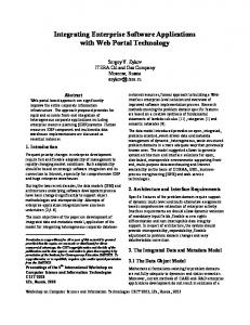
Fig. 1. Singular values of GH G for i.i.d. Rayleigh fading.
100
M = 200 K = 20
0,8
0,6
10
M = 100 K = 10
0,8
Cumulative Distribution
Cumulative Distribution
0,8
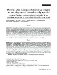
Fig. 2. Same as Figure 1, but for UR-LoS.
Here, (M = 100, K = 10) and (M = 200, K = 20). 4.3. Urns-and-Balls Model for UR-LoS In Section 4.2, we assumed that angles {θk } are fixed and distinct regardless of M . With this assumption, we have asymptotically favorable propagation. However, if there exist {θk } and {θj } such that sin(θk ) − sin(θj ) is in the order of 1/M , then we cannot have favorable propagation. To see this, assume that sin(θk ) − sin(θj ) = 1/M . Then 1 1 − eiπ(sin(θk )−sin(θj ))M 1 H 1 1 − eiπ gk gj = = M M 1 − eiπ(sin(θk )−sin(θj )) M 1 − eiπ/M 2i 6= 0, M → ∞. (22) → π In practice, M is finite. If the number of terminals K is in order of tens, then the probability that there exist {θk } and {θj } such that sin(θk ) − sin(θj ) ≤ 1/M cannot be neglected. This makes the channel unfavorable. This insight can be confirmed by the following examples. Let consider the singular values of the Gramian matrix GH G. Figures 1 and 2 show the cumulative probabilities of the singular values of GH G for i.i.d. Raleigh fading and UR-LoS channels, respectively. We can see that in i.i.d. Rayleigh fading, the singular values are uniformly spread out between σmin and σmax . However, for UR-LoS, two (for the case of M = 100, K = 10) or three (for the case of M = 200, K = 20) of the singular values are very small with a high probability. However, the rest are highly concentrated around their median. Therefore, in order to have favorable propagation, we must drop some terminals from service. In the above examples, we must drop two terminals for the case M = 100, K = 10 or three terminals for the case M = 200, K = 20, with high probability. To quantify approximately how many terminals that have to be dropped from service so that we have favorable propa-
gation with high probability in the UR-LoS case, we propose to use the following simplified model. The base station array can create M orthogonal beams with the angles {θm }: sin (θm ) = −1 +
2m − 1 , M
m = 1, 2, ..., M.
(23)
Suppose that each one of the K terminals is randomly and independently assigned to one of the M beams given in (23). To guarantee the channel is favorable, each beam must contain at most one terminal. Therefore, if there are two or more terminals in the same beam, all but one of those terminals must be dropped from service. Let N0 , M − K ≤ N0 < M , be the number of beams which have no terminal. Then, the number of terminals that have to be dropped from service is Ndrop = N0 − (M − K) .
(24)
By using a standard combinatorial result given in [6, Eq. (2.4)], we obtain the probability that n terminals, 0 ≤ n < K, are dropped as follows: P (Ndrop = n) = P (N0 −(M − K) = n) = P (N0 = n+M −K) � � M = n+M −K �K � �� K−n X n+M −K +k k K −n . (25) 1− (−1) × M k k=1
Therefore, the average number of terminals that must be dropped from service is ¯drop = N
K−1 X n=1
nP (Ndrop = n) .
(26)
Cumulative Distribution
1.0
computed by using (25). We can see that the probability that three terminals (for the case of M = 100, K = 10) and four terminals (for the case of M = 200, K = 20) must be dropped is less than 1%. This is in line with the result in Fig. 2 where three (for the case of M = 100, K = 10) or four (for the case of M = 200, K = 20) of the singular values are substantially smaller than the rest, with probability less than 1%. Note that, to guarantee favorable propagation, the number of terminals must be dropped is small (≈ 20%).
i.i.d. Rayleigh, exact i.i.d. Rayleigh, bound UR-LoS, exact UR-LoS, bound
0.8 0.6 0.4
ρ = -10 dB
ρ = 0 dB
0.2
2
4
6
8
6. CONCLUSION
bits/channel use/terminal
Fig. 3. Capacity per terminal for i.i.d. Rayleigh fading and
UR-LoS channels. Here M = 100 and K = 10.
P(Ndrop= n)
10 10 10 10 10
0
M =100, K =10 M =200, K =20
-1
-2
-3
-4
0
2
4
6
8
10
Number of Terminals Dropped from the Service (n)
Fig. 4. The probability that n terminals must be dropped from
service, using urns-and-balls model for UR-LoS propagation. Remark 1 The result obtained in this subsection yields an important insight: for Rayleigh fading, terminal selection schemes will not substantially improve the performance since the singular values are uniformly spread out. By contrast, in UR-LoS, by dropping some selected terminals from service, we can improve the worst-user performance significantly. 5. EXAMPLES AND DISCUSSIONS Figure 3 shows the cumulative probability of the capacity per terminal for i.i.d. Rayleigh fading and UR-LoS channels, when M = 100 and K = 10. The “exact” curves are obtained by using (5), and the “bound” curves are obtained by using the upper bound (6) which is the maximum sum-capacity achieved under favorable propagation. For both Rayleigh fading and UR-LoS, the sum-capacity is very close to its upper bound with high probability. This validates our analysis: both independent Rayleigh fading and UR-LoS channels offer favorable propagation. Note that, despite the fact that the condition number for UR-LoS is large with high probability (see Fig. 1), we only need to drop a small number of terminals (2 terminals in this case) from service to have favorable propagation. As a result, the gap between capacity and its upper bound is very small with high probability. Figure 4 shows the probability that n terminals must be dropped from service, P (Ndrop = n), for two cases: M = 100, K = 10 and M = 200, K = 20. This probability is
Both i.i.d. Rayleigh fading and LoS with uniformly random angles-of-arrival offer asymptotically favorable propagation. In i.i.d. Rayleigh, the channel singular values are well spread out between the smallest and largest value. In UR-LoS, almost all singular values are concentrated around the maximum singular value, and a small number of singular values are very small. Hence, in UR-LoS, by dropping a few terminals, the propagation is approximately favorable. The i.i.d. Rayleigh and the UR-LoS scenarios represent two extreme cases: rich scattering, and no scattering. In practice, we are likely to have a scenario which lies in between of these two cases. Thus, it is reasonable to expect that in most practical environments, we have approximately favorable propagation. The observations made regarding the UR-LoS model also underscore the importance of performing user selection in massive MIMO. REFERENCES [1] T. L. Marzetta, “Noncooperative cellular wireless with unlimited numbers of base station antennas,” IEEE Trans. Wireless Commun., vol. 9, no. 11, pp. 3590–3600, Nov. 2010. [2] J. Hoydis, S. ten Brink, and M. Debbah, “Massive MIMO in the UL/DL of cellular networks: How many antennas do we need?” IEEE J. Sel. Areas Commun., vol. 31, no. 2, pp. 160–171, Feb. 2013. [3] E. G. Larsson, F. Tufvesson, O. Edfors, and T. L. Marzetta, “Massive MIMO for next generation wireless systems,” IEEE Commun. Mag., vol. 52, no. 2, pp. 186– 195, Feb. 2014. [4] H. Q. Ngo, E. G. Larsson, and T. L. Marzetta, “Energy and spectral efficiency of very large multiuser MIMO systems,” IEEE Trans. Commun., vol. 61, no. 4, pp. 1436–1449, Apr. 2013. [5] F. Rusek, D. Persson, B. K. Lau, E. G. Larsson, T. L. Marzetta, O. Edfors, and F. Tufvesson, “Scaling up MIMO: Opportunities and challenges with very large arrays,” IEEE Signal Process. Mag., vol. 30, no. 1, pp. 40– 60, Jan. 2013. [6] W. Feller, An Introduction to Probability Theory and Its Applications, 2nd ed. New York: Wiley, 1957, vol. 1.


![arXiv:1403.3173v1 [math.FA] 13 Mar 2014](https://m.moam.info/img/260x300/arxiv14033173v1-mathfa-13-mar-2014_5a32f84c1723ddf6ae3d486f.jpg)
![arXiv:1403.3401v1 [hep-ph] 13 Mar 2014](https://m.moam.info/img/260x300/arxiv14033401v1-hep-ph-13-mar-2014_5a32f5731723ddf4aec5f3c6.jpg)
![arXiv:1403.3288v1 [cond-mat.mes-hall] 13 Mar 2014](https://m.moam.info/img/260x300/arxiv14033288v1-cond-matmes-hall-13-mar-2014_5a32f8a11723ddf4aec5f3f8.jpg)


![0203124v1 [math.MG] 13 Mar 2002](https://m.moam.info/img/260x300/0203124v1-mathmg-13-mar-2002_5c653628097c475b5f8b45b2.jpg)
![0603296v1 [math.CO] 13 Mar 2006](https://m.moam.info/img/260x300/0603296v1-mathco-13-mar-2006_5c7285a5097c4783508b46c1.jpg)
![0703025v1 [nlin.SI] 13 Mar 2007](https://m.moam.info/img/260x300/0703025v1-nlinsi-13-mar-2007_5c9425a7097c474d0a8b46b1.jpg)