Section III reviews communication options for Smart Grid applications and .... communication vehicles acting as base stations during emergencies. This is.
Communication Networks for Smart Grid (IEEE SmartGridComm)
Assessing Communications Technology Options for Smart Grid Applications Amar Patel∗ , Juan Aparicio∗ , Nazif Tas∗ , Michael Loiacono† and Justinian Rosca∗ ∗ Siemens
Corporate Research 755 College Road East Princeton, NJ, 08540
† Siemens
Energy, Inc 7000 Siemens Rd. Wendell, NC, 27591
{amar-patel,juan.aparicio.ext,nazif.tas,michael.loiacono,justinian.rosca}@siemens.com
Abstract—Utilities are at a crossroads in addressing challenges to architect communication networks that can support a robust blend of smart grid applications while simultaneously meeting stringent financial and regulatory objectives. This paper discusses challenges in understanding the communication network choices when supporting applications such as Distribution Automation, Advanced Metering, Automated Demand Response and Electric Vehicle Charging. We also introduce the unique capabilities of a tool designed to evaluate different communications technology choices under specific application, network, topology, and geographical constraints.
I. I NTRODUCTION The utility industry is undergoing a major transformation that will enable demand management, reliability gains, resource efficiency, customer participation, and cleaner energy across the grid. This transformation is being facilitated via the deployment of so-called smart grid applications such as smart metering, demand response, and feeder automation. The common thread across such applications is that they must be enabled via sophisticated communications networks - particularly in the region from the distribution substation out to the meter, and into the home. This is an area where utilities have historically not deployed complex communication systems. Unfortunately, the deployment of evolved networks has not been a painless process for North American utilities. The present landscape of available technologies is vast, and the communication needs of each utility and each smart grid application are unique. This has led to scenarios of increased complexity (e.g. utilities deploy disparate communications networks for each individual application), increased OPEX, unexpected application behavior due to improper communication technology choices, and an overall uncertainty among utilities about the best use of their capital. Modernizing the power grid involves overlaying a robust information infrastructure over the traditional power systems infrastructure, and leveraging massive amounts of real-time data from a myriad of sensors and intelligent devices. The decisions utilities make around communications technology largely influence the degree of long-term success they achieve in their strategic objectives such as refueling the generation fleet, improving operational efficiency, improving consumer
978-1-4577-1702-4/11/$26.00 ©2011 IEEE
126
engagement, and integrating renewables [1]. This paper discusses the challenges in understanding Smart Grid communications technology choices, and presents a tool to facilitate optimal decision making. Our focus is on so-called field and neighborhood area networks, which cover the domain from the distribution substation to the customer premises, and support applications such as feeder automation and advanced metering. The information and communication infrastructure enables the scalable handling of large quantities of data and multidirectional exchange of control and management information. For instance, communications networks for feeder automation provide low latency, high capacity information exchange between distribution substations, protection relays, recloser controllers, and other intelligent electronic devices. A contrasting, but equally important example is Automated Metering Infrastructure, which requires highly-scalable, but latency-tolerant communications to acquire and backhaul meter data. Distribution automation networks provide capabilities to network substations and distribution automation endpoints. Advanced metering networks are needed to backhaul meter data [2]. The myriad of distribution devices have more stringent latency and bandwidth requirements for mission-critical operations in comparison to the meter data. The paper is organized as follows. Section II discusses data traffic models associated with popular smart grid applications. Section III reviews communication options for Smart Grid applications and highlights outstanding networking challenges: coverage, performance, availability of network, and scalability. We have developed a sophisticated communications modeling and simulation tool for studying the functional behavior of any combination of smart grid applications as a function of the underlying communications technologies, asset topologies and geographical terrain of a utilitys service area. Section IV introduces our Smart Grid Communications Assessment Tool (SG-CAT) that addresses these challenges, evaluates different communication network options and offers recommendations. Our preliminary results using SG-CAT are also presented in this section. Finally, Section V concludes the paper and highlights additional important challenges not included here, but worthy of seperate discussion.
Application AMI ADR FA EV MWM
Type of Transmission periodic or event-based, unicast periodic or event-based, unicast periodic and event based, multicast event-based, unicast evet- based, unicast
Requirements Bandwidth 10 kb/message/node
One/Two Way one/two
Frequency low
Latency high
Real-Time low
one/two
medium
medium-high
14-100 kbps/node
medium
two
high
low
50-200 kbps
high
two
event based
medium-high
9.6 - 56 kbps
medium-high
two
event based
low-medium
application dependant (up to 1500 kbps)
medium-high
TABLE I A PPLICATIONS AND COMMUNICATION REQUIREMENTS .
II. A PPLICATION R EQUIREMENTS We introduce common Smart Grid applications and elaborate on their specific communication needs. Detailed knowledge about these applications allows us to define realistic traffic models needed in large scale simulation experiments. Application characteristics are summarized in Table I. A. Advanced Metering Infrastructure (AMI) The foremost Smart Grid application that has been widely discussed is the Advanced Metering Infrastructure (AMI). In addition to the evident functionality of remote measurement readings, AMI might include capabilities such as remote meter management (i.e. disconnecting/reconnecting the customers [3]), recording and transferring the event logs and security logs [4] and outage reporting [5]. A typical AMI application requires infrequent uplink transfers with small packet sizes. However, as this operation has to be completed for a very large customer base spread over a large geographical area, the throughput and response time have to considered as important metrics at the network design phase [6]. Moreover, broadcasting and multicasting functionality should be supported in an AMI network in order to avoid sequential meter readings [3]. B. Automated Demand Response (ADR) Automatic Demand Response (ADR) is a means for utility companies and the customers to reduce the power consumption, save energy and utilize the capacity of the distribution system infrastructure through reducing or eliminating the need for building new lines and expanding the electrical system [7]. ADR applications offer benefits for both the utility companies and the customers. For instance, load reduction incentives offered by the utility companies to the customers (through mechanisms such as determining the maximum potential customer segments and adequate demand response policies [8]) allow the former to avoid peak energy consumption and unnecessary high costs invested in peak generation. Similarly, the customers can utilize the real-time pricing schedules in order to decide on electric consumption and shift their demand over time as necessary, resulting in better expense savings [9]. ADR applications require continuous, reliable, two-way communication with a diverse set of end-use strategies such as pre-cooling for ”day ahead” notification or near real-time communications to automation ”day of” control strategies [10].
127
C. Feeder Automation (FA) Automated supervision and control of substations allows overall coordination in case of emergencies and optimizations of operating costs. The communication system is a vital part of the wide area power system relaying and coordination. Relays isolate local failures in generation, transmission and distribution so that they do not spread to other parts of the grid. Distributed feeder automation refers to substation equipment for the detection, location, and isolation of faults, and a means to restore power to undamaged sections of line. This functionality is referred to as Fault Location, Isolation, and Supply Restoration (FLISR). A typical feeder system includes a circuit breaker and at least three of the following types of switching devices distributed along the line: reclosers, disconnect switches, sectionalizers, airbreak switches, and fuses [11]. Distributed feeder automation systems today employ wireless connectivity form a centralized master controller to various system components. [11] presents a DFA FLISR system using IEC61850 GOOSE messaging protocol over WiMAX. The system distributes logic amongst relays to implement a decentralized control system. D. Electric Vehicle Charging (EV) Different studies show that Electric Vehicles (EV) will have a penetration of 5% of the market by 2020 [12] and they will continue to grow even faster over the following years. This means that millions of vehicles need to be integrated into the power supply infrastructure. A large fleet of EVs needs to be managed in an intelligent way in order to optimize and control the charging of their batteries without generating uncontrollable load peaks. In this sense, a suitable, reliable and efficient communication infrastructure needs to be deployed. This communication network needs to be secure, with sufficient throughput, low latency and be cost-efficient. In order to achieve a trustworthy network, several challenges need to be solved: reliability, real-time behavior, scalability, and above all a common standard that regulates the communications involved in the charging process. [13] and [14] propose the use of the Session Initiation Protocol (SIP) for the communication messages between the EV and the Virtual Power Plant (VPP). SIP is a mature protocol and has proven to be reliable, secure and scalable. A different approach has been taken in [15] to demonstrate how the ISO/IEC V2G Communication Interface can fulfill the
requirements of the EV communications between the vehicle and the supply equipment (EVSE). For the integration into the smart grid and the communications between the EVSE and the VPP they propose the IEC 61850 protocol. E. Mobile Workflow Management (MWM) Smart Grid will reduce the necessity of field workers that go home by home collecting data readings. However, competent installation and repair of smart grid meters and other pieces of equipment is still necessary. In this sense, in-vehicle connectivity, fleet management and secure broadband connectivity are essential requirements for the future workforce. In addition, new applications will be developed, such as firmware update, configuration management, compatibility checking, etc. These applications will require high throughput, security measures, support for mobility and QoS. Table I summarizes the main communication requirements of these applications in terms of frequency of messaging, latency, bandwidth and real-time needs. The challenge is to simultaneously address a large subset of these applications. This will be done through assessing the choices for different communication technologies that allow the deployment of a reliable network. Next section introduces a description of the main communication technologies, underlying advantages and disadvantages when they fulfill the different Smart Grid application requirements. III. C OMMUNICATION O PTIONS The successful implementation of different Smart Grid applications hinges on the choice of communication technology. Widely ranging requirements and characteristics of each application, technology and deployment scenario make the planning of the communication infrastructure a nontrivial and cumbersome task. There is currently no silver bullet communications technology that fits all the needs of the Smart Grid. In the following sections, we summarize the communication technologies commonly deployed for the Smart Grid. A. Review of Smart Grid Communication Technologies 1) Cellular Networks: In recent years, cellular networks have experienced a constant evolution that has been translated in a dramatic increase in communication speed. We have evolved from the 56-115 Kbps of GPRS to the 2Mbps in 3G and recently to the 50-100 Mbps of 4G-LTE [16]. The high throughput and the extensive geographic coverage of cellular networks make this technology an attractive choice capable of meeting the Smart Grid data transmission requirements. Moreover, the pre-existence of the network allows for rapid deployment of additional applications. Furthermore, the wide spread support of LTE by large network carriers and chipsetdevice manufacturers is expected to lower the hardware prices. At the same time, in order to properly deal with data privacy and prioritization, carriers must be willing to offer flexible new Service Level Agreements to utilities. A possible solution to this problem can be the use of emergency communication vehicles acting as base stations during emergencies. This is the scenario studied in [17], where the authors demonstrate
128
that LTE technology can fully meet the data rate, error rate and delay requirements in an emergency situation. As another example, some applications like EV can be deployed using just the GSM network and SMS text messages [18]. 2) RF-Mesh: Radio Frequency Mesh (RF-Mesh) networks represent the concept of a collective, self-organizing communication infrastructure in which all the members of the network perform additional routing functionalities such as packet forwarding and route creation, in addition to the usual application-specific tasks. Through multi-hop communications, an RF-Mesh can achieve greater coverage areas with much lower transmission power, and provides other advantages such as robustness and reliable service coverage [19]. The self-organizing and self-healing capabilities of an RF Mesh promote a resilient network infrastructure which adapts to changing conditions automatically and autonomously, albeit often at the expense of reduced network capacity, increased latency, and complex network management. In today’s communication domain, many RF-Mesh choices exist for different network setups and requirements, such as IEEE 802.11s [20] for high-bandwidth applications and ZigBee [21] for low-power smart devices. The choice of technology heavily depends on application requirements, connectivity between the network members and user capabilities. 3) Other Outstanding Choices: WiMAX: The main characteristics of this technology are high throughput (40Mbps in IEEE 802.16j-2009 [22] and up to 300Mbps in the next release IEEE 802.16m), low latency (less than 100ms round trip [23]), multiple security standards (AES, AAA, etc.) and traffic management tools (traffic prioritization, QoS, etc.). In addition, developing a WiMAXbased architecture would require building a utility-proprietary network, which has advatages such as complete control over traffic management tools and network performance during both regular operations and emergencies; and disadvantages such as high cost to achieve ubiquitous coverage. Power Line Communication (PLC): PLCs transmit the data over the electric power conductors, which both represents advantage and disadvantages. On the positive side, hardware cost is reduced as the power grid is utilized for information transfer simultaneously with the electric power distribution. Conversely, PLC signals are killed by the MV/ LV transformers and can be induced with large amounts of noise from un-insulated power lines that act as antennas. To address this issue, the IEEE 1901.2 project is developing a standard that will sustain communications through the MV/LV transformer with data rates up to 500 kbps. Current research efforts in this technology make some authors optimistic about the use of PLCs for several Smart Grid applications [24]. Several proprietary options of Smart Grid communication technologies exist, such as the Tropos Private WiFi system and the point to point RF solution by Sensus. These examples highlight the fact that the choice of an optimal technology, as highlighted throughout this paper, depends on many factors such as different types of applications in use, the level of existent technology infrastructure, the geographical
60
5
Free Space Suburban Longley-Rice
50
4
40 30
Range (km)
SNR (dB)
Free Space Longley-Rice, AP-M Longley-Rice, M-M
20 10 0
3
2
1
-10 -20
Fig. 1.
0
2
4
6 Distance (km)
8
0
10
Path loss observations for three different propagation models.
characteristics of the deployment region, etc.
0
2
Fig. 2.
4
6 8 10 12 Transmit Power (dBm)
14
16
18
Terrain effect on the range for RF-Mesh.
be considered carefully during the network planning phase.
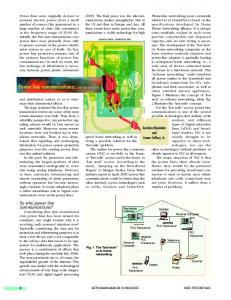
B. Communication Challenges Terrain information is important in large scale studies, as hilly regions offer different challenges compared to flat regions. When considering the signal attenuation of a transmitter as a function of distance, many pathloss models exist. Free space pathloss is not valid after some distance as foliage and obstacles begin to play a role. The Suburban pathloss model defined in [25] shows that wireless communication in an outdoor environment is affected by the amount of hilliness and tree density in the region. Such a empirical model provides better results then free space on average, as it accounts for signal attenuators in the region. However, even such models rely on a simple one-slope characterization of pathloss, which does not consider particular variations of the terrain. It is important to take the height of the antennas and the particular horizon seen by the antennas into account, since even connectivity might not be possible. Longley Rice [26] is one such model that considers freespace propagation, ground reflection, terrain diffraction, and, for long antenna distances, scattering. Figure 1 shows the pathloss for these three models. In an RF-Mesh deployment, the effective range of communication heavily depends on the absolute altitude and orientation of the transmitter and receiver. Access points and relays are typically mounted on pole tops or other high locations, whereas Smart Meters are more likely to be found closer to the ground. A meter-to-AP hop would be the final hop, a meterto-relay hop would be used to overcome the coverage gaps, and a meter-to-meter hop would be used to form a long range multi-hop mesh network. In a cellular deployment, the terrain profile between a meter and base station directly impacts whether connectivity can be established or not. Unlike an RFMesh deployment, a cellular network cannot use intermediate devices to relay information and keep connectivity. Regardless of technology in use, since all users share the same medium, the number of users in the network impacts the quality of service in terms of expected latency, delay jitter and achieved throughput. In extreme cases, it may even cause the network to collapse. Since each communication technology handles additional users differently, the network size should
129
IV. S MART G RID C OMMUNICATIONS A SSESSMENT T OOL We address the challenges aforementioned with the Smart Grid Communications Assessment Tool (SG-CAT), which is capable of simulating various Smart Grid applications under various geographical and asset topologies, user orientations and application configurations and specifications. Our tool models and evaluates the communication capabilities of a given Smart Grid deployment, develops a list of communication options to consider, and offers recommendations. A. SG-CAT Outline The simulations reported in this paper are based on our SGCAT tool that was developed on top of OPNET Modeler. OPNET Modeler is a powerful discrete event network simulator that provides high-fidelity modeling and detailed analysis for very large wired and wireless networks. The different OPNET Modeler solutions enable the users to model various kinds of networks using a broad range of wireless protocols and technologies in realistic scenarios which take the effects of the terrain, the mobility of the nodes and multiple pathloss models into consideration. SG-CAT enables the analysis of possible network topologies for diverse utility requirements and existing architectures, topology scale up, and analysis of end-to-end behavior of customized Smart Grid applications. Furthermore, it allows the users to tune up different network parameters and evaluate growth scenarios for performance studies. In addition, SGCAT provides the capability of incorporating power system components through co-simulation using Siemens’s PSS@E. Multiple co-simulation systems can run simultaneously and exchange information (boundary conditions, events, time steps, control signals, etc.) in a collaborative manner within the SGCAT environment, in order to perform hybrid complex Smart Grid simulations that let the users understand the interactions at the design and analysis stages. In the following sections, we report on some of our findings through the SG-CAT tool.
850
150 Mean (msec)
Elevation (m)
Terrain
800
RF Mesh Cellular
100
750 700 0
2
4
6
8
50 0
1 0
25
Out
0 0
2
4
6
Number of hops
D i s t a n c e
8
2 0
4 0
6 0
100
Delay (msec)
75 50
10 9 8 7 6 5 4 3 2 1 0
Standard Deviation (msec)
100
Connectivity Delay
In
1 0
( k m )
200
8 0
1 0 0
1 2 0
1 4 0
1 6 0
1 8 0
2 0 0
RF Mesh Cellular
50
0
0
20
40
60
80 100 120 140 160 180 200 Number of Users
Fig. 4. Multiuser delay observations for RF-Mesh and cellular technologies. 150
Delay (msec)
Network Coverage
0
100
0
2
4
6 Distance (km)
Number of hops Delay 8 10
50 0
Fig. 3. Coverage simulation results. top: The terrain profile of the simulation; middle: delay and coverage observations from the LTE network setup; bottom: delay and number of hops metric from the RF-Mesh setup.
B. Simulation Setup We have chosen the RF-Mesh and cellular technologies as the focus of our preliminary analysis. The RF-Mesh module, based on the IEEEs 802.15.4g SUN work group specifications, operates in the unlicensed 902-928MHz ISM band with QAM64 Modulation and 100 kbps. For testing the cellular technology, we use an LTE network configured for 10MHz Frequency Division Duplex. C. Results and Discussions 1) RF-Mesh Range: Figure 2 follows our discussions from Section III-B and reports observations about the effect of the deployment terrain on an important network performance metric, the transmission range. In this simulation, we consider two different antenna orientations: a) both the transmitter and the receiver antennas were placed at a height of 2 meters (labeled as M-M as it resembles the meter-to-meter setting), and b) the receiver antenna was kept at 2 meters whereas the transmitter antenna was elevated to 10 meters (labeled as AP-M as it resembles Access Point-to-meter setting). For varying RF-Mesh power levels, we observe that the terrain characteristics might reduce the effective transmission range as much as 50% compared to free space propagation. The results indicate that when the receiver is placed at a low height, a communication range of about 1 km is feasible. However, the range extends to about 1.5 km when the receiver is situated at a higher location. Note that these results depend on the terrain profile of the testing area, and the effective ranges are expected to vary in other terrain settings.
130
These results suggest that meter-to-meter hops (introduced in Section III-B) are possible over the range of hundreds of meters and high altitude relays can be used to further extend range in case of coverage gaps. 2) Coverage: For testing coverage areas, a receiver was placed at a fixed location, representing the takeout point. The resulting connectivity of the networks (RF-Mesh and LTE) is observed in a range of 11 km in one direction. In Figure 3, the terrain profile of the simulation, shown in the top graph, exhibits hills and valleys of about 20m in altitude. Such obstructions cause the mesh network to use short hops at certain locations. Yet, network connectivity is never lost because of the self-healing capability of RF-Mesh. A mesh path can always be constucted between intermediate devices, which utilize adjacent hops to avoid network disconnectivity. However, in the case of an LTE network, the transmitter must always have direct connection to the end receiver, so coverage gaps might not be avoided even though LTE links can support longer ranges than single RF-Mesh links. The terrain characteristics not only have an effect on connectivity, but also on the quality of service. An RF-Mesh experiences increased delay due to the necessity for additional hops; wheras in an LTE network, additional delay might come from bad channel conditions causing retransmissions and other link adaptation mechanisms inherent to LTE networks (i.e., a lowering of the MCS index). Note that these results only focus on the coverage in one direction, and the challenges are magnified when a 360 degree view is taken into consideration, since the terrain profile, and accordingly the obtained coverage will vary in each direction. 3) Network Size: In Figure 4, the impact of network size was studied by increasing the number of users that occupy a 4km distance from the takeout point. By observing the average delay experienced by all users, we see that RF-Mesh’s latency is heavily dependent on the number of users in the network. However, the users in LTE network, with its high bandwidth, experience a less severe affect on their latencies. At the same time, the increase in users cause a less reliable
100
0.1 packets/minute 0.2 packets/minute 0.4 packets/minute
Reception Rate (%)
80
60
40
20
0
0
20
40 60 Packet Size (KB)
80
100
Fig. 5. RF-Mesh packet size and transmission frequency effect on reception.
latency guarantee as can be seen in the standard deviation graph. As these results suggest, the network size has to be considered carefully during the planning phase of the network and necessary configuration should be done accordingly to ensure an adequate level of service (e.g. low latency and/or low jitter requirements of the applications should be addressed). 4) Multi-Application: The Smart Grid network is expected to handle multiple applications with diverse requirements (see Table I) concurrently. In our final simulation, we focus on two important communication parameters, the transmission packet size and the transmission frequency in order to assess the RF-Mesh network’s capability to satisfy different applications. Figure 5 shows that the packet size has a massive effect on the reception rate (the percentage of the packets that is received correctly by the intended receiver) and in case of higher frequency transmissions, the maximum packet size is further reduced. On the other hand, LTE cellular networks exhibit 100% reception rate for the same simulation setup. Hence, the application requirements have a direct effect on the choice of the network technology. V. C ONCLUSIONS Utilities face significant challenges to architect large scale smart grid communication networks today. The question of which technology fits one’s specific bill is multifaceted. At one end, requirements for a mix of business-grounded, still evolving applications are divergent. At the other end, specific technologies (of which RF-Mesh and LTE are contrasted in this paper) experience unique challenges in coverage, delay, and reliability due to real-world terrain constraints, details of real-world deployment, user density, and implementation details of the applications. This makes it complex to assess networks in the large. We have developed a tool, SG-CAT, to evaluate scale up for large coverage by considering all these details. While the paper has focused on describing these challenges, future work will evaluate large scale networks. R EFERENCES [1] J. McDonald, Electric power substations engineering, ser. Electric power engineering handbook. CRC Press, 2007. [2] M. Torchia, “Top 10 Considerat ions in Select ing a Dist r ibut ion Area Network for Smar t Gr ids,” 2011, tropos Networks White Paper.
131
[3] G. Deconinck, “An evaluation of two-way communication means for advanced metering in Flanders (Belgium),” in Instrumentation and Measurement Technology Conference Proceedings, 2008. IMTC 2008. IEEE, may 2008, pp. 900 –905. [4] R. Vaswani and E. Dresselhuys, “Implementing the right network for the Smart Grid: Critical infrastructure determines long-term strategy,” silver Spring Networks, White Paper. [5] D. Hart, “Using AMI to realize the Smart Grid,” in Power and Energy Society General Meeting - Conversion and Delivery of Electrical Energy in the 21st Century, 2008 IEEE, july 2008, pp. 1 –2. [6] S. Mak and D. Radford, “Design considerations for implementation of large scale automatic meter reading systems,” Power Delivery, IEEE Transactions on, vol. 10, no. 1, pp. 97 –103, jan 1995. [7] Q. Dam, S. Mohagheghi, and J. Stoupis, “Intelligent demand response scheme for customer side load management,” in Energy 2030 Conference, 2008. ENERGY 2008. IEEE, nov. 2008, pp. 1 –7. [8] S. Valero, M. Ortiz, C. Senabre, C. Alvarez, F. Franco, and A. Gabaldon, “Methods for customer and demand response policies selection in new electricity markets,” Generation, Transmission Distribution, IET, vol. 1, no. 1, pp. 104 –110, january 2007. [9] K. Spees and L. Lave, “Impacts of responsive load in pjm: load shifting and real time pricing,” The Energy Journal, 2008. [10] E. Koch and M. A. Piette, “Architecture concepts and technical issues for an open, interoperable automated demand response infrastructure,” Lawrence Berkeley National Laboratory, Tech. Rep., 2007. [11] A. Smit, “Distribution Feeder Automation using IEC61850 GOOSE Messaging over WIMAX Wireless Communications.” [12] “United States Department of Energy, Energy Information Administration, 2011 Energy Outlook.” [13] J. DiAdiamo, “SIP Open Communications for Smart Grid Devices,” Siemens, Position Paper, 2009. [14] B. Jansen, C. Binding, O. Sundstroo andm, and D. Gantenbein, “Architecture and communication of an electric vehicle virtual power plant,” in Smart Grid Communications (SmartGridComm), 2010 First IEEE International Conference on, oct. 2010, pp. 149 –154. [15] S. Ka andbisch, A. Schmitt, M. Winter, and J. Heuer, “Interconnections and communications of electric vehicles and smart grids,” in Smart Grid Communications (SmartGridComm), 2010 First IEEE International Conference on, oct. 2010, pp. 161 –166. [16] 3GPP, “Requirements for Evolved UTRA (E-UTRA) and Evolved UTRAN (E-UTRAN) (Release 9), 3GPP 25.913 V9.0.0,” 2009. [17] Z. Feng, L. Jianming, H. dan, and Z. Yuexia, “Study on the application of advanced broadband wireless mobile communication technology in smart grid,” in Power System Technology (POWERCON), 2010 International Conference on, oct. 2010, pp. 1 –6. [18] C. Hochgraf, R. Tripathi, and S. Herzberg, “Smart grid charger for electric vehicles using existing cellular networks and sms text messages,” in Smart Grid Communications (SmartGridComm), 2010 First IEEE International Conference on, oct. 2010, pp. 167 –172. [19] I. Akyildiz and X. Wang, “A survey on wireless mesh networks,” Communications Magazine, IEEE, vol. 43, no. 9, pp. S23 – S30, sept. 2005. [20] G. Hiertz, D. Denteneer, S. Max, R. Taori, J. Cardona, L. Berlemann, and B. Walke, “IEEE 802.11s: The WLAN Mesh Standard,” Wireless Communications, IEEE, vol. 17, no. 1, pp. 104 –111, february 2010. [21] A. Wheeler, “Commercial Applications of Wireless Sensor Networks Using ZigBee,” Communications Magazine, IEEE, vol. 45, no. 4, pp. 70–77, 2007. [22] “Ieee standard for local and metropolitan area networks part 16: Air interface for broadband wireless access systems amendment 1: Multiple relay specification,” IEEE Std 802.16j-2009 (Amendment to IEEE Std 802.16-2009), 12 2009. [23] “Empowering the smart grid with WiMAX,” SenzaFilling Consulting, Tech. Rep., 2010. [24] S. Galli, A. Scaglione, and Z. Wang, “For the grid and through the grid: The role of power line communications in the smart grid,” CoRR, vol. abs/1010.1973, 2010. [25] V. Erceg, “An empirically based path loss model for wireless channels in suburban environments,” IEEE JSAC,, vol. 17, no. 7, pp. 1205–1222, 1999. [26] A. G. Longley and P. Rice, “Prediction of tropospheric radio transmission loss over irregular terrain, a computer method-1968,” ESSA Technical Report ERL 79-ITS 67 Institute for Telecommunications Sciences, Tech. Rep., 1968.