Center-TRACON Automation System (CTAS), which comprises a set of automation tools for air traffic controllers [8]. A different kind of TS is also incorporated in ...
25TH INTERNATIONAL CONGRESS OF THE AERONAUTICAL SCIENCES
AUTOMATED CONFLICT RESOLUTION FOR AIR TRAFFIC CONTROL Heinz Erzberger Senior Scientist (retired), NASA Ames Research Center, Moffett Field, CA 94035 Professor (Adjunct) of Electrical Engineering University of California, Santa Cruz
Keywords: Air traffic management, separation assurance, conflict resolution
Abstract
1 Introduction
This paper describes a conflict resolution algorithm that can provide automated separation assurance for the next generation air traffic control system. The algorithm generates resolution trajectories that can be sent to the aircraft from a ground-based system via data link. The algorithm can also be installed on board aircraft. It handles the complete spectrum of conflict types encountered in en route airspace, including ascents and descents to arrival fixes. The resolution trajectories consist of amendments and changes to flight plans (route changes), altitude clearances, and descent speed profiles. The trajectories are similar to those that controllers customarily issue to pilots in resolving conflicts. The algorithm generates 4D resolution trajectories by evaluating successive alternative trial resolution maneuvers. Each conflict type determines a set of acceptable trial resolution maneuvers and what the preferred aircraft is to perform the maneuver. A trajectory engine generates a 4D trajectory for each trial maneuver, and an associated conflict detector checks it to ensure it is conflict free. If it is not, the algorithm selects an alternative maneuver. This iterative process continues until a successful resolution is found. The resolution algorithm has been implemented and evaluated in a non-real time simulation, and its performance in resolving conflicts for a range of traffic levels is presented in this paper. Results indicate that the algorithm has the potential to resolve conflicts efficiently at significantly higher than current traffic levels.
A reliable and efficient system for resolving conflicts automatically is believed to be an essential component of the next generation air traffic control system. While systems for conflict detection, such as Conflict Alert, have been used operationally by controllers for more than 20 years, systems for automated resolution have not been successfully developed for operational use. Past research on automated resolution often assumed predefined resolution types, primarily horizontal maneuvers [1]-[6]. Controllers, on the other hand, choose horizontal, altitude, or speed maneuvers to resolve conflicts, and adapt their choice based on the characteristics of the conflict encounter and on other factors. Furthermore, resolution algorithms have been derived on the assumption that both aircraft in conflict are flying at constant altitude and speed along straight-line paths. Analysis of actual operations shows, however, that such conflicts constitute less than half of all conflicts encountered in complex en route airspace. Another limitation of previously developed resolution methods is that they are based on simplified aircraft dynamics and trajectory models, making the resulting resolution trajectories difficult or impossible for aircraft to fly accurately. None of the techniques developed to date have been evaluated in realistic simulations to determine whether they can effectively resolve the full range of conflict that controllers handle routinely. The resolution algorithm described in this paper was designed for use in the Automated Airspace Concept (AAC) [7]. The AAC is 1
HEINZ ERZBERGER
intended to increase safety and airspace capacity and to accommodate user preferences in flight operations to the greatest extent possible. In this concept, a system on the ground generates resolution trajectories that it then sends to the aircraft via a data link. The ground-based system verifies that the resolution trajectories are safe before they are sent to the aircraft. Because controllers are not required to approve the trajectories, the workload for controllers is reduced, permitting traffic density to be increased substantially. The algorithm that generates the trajectories must take into account the performance characteristics of the aircraft and must be capable of resolving all types of conflicts without requiring a controller’s supervision and approval. Therefore, the algorithm must be capable of producing resolutions for the complete spectrum of conflict encounters that controllers are able to handle manually. Furthermore, in order to be acceptable to pilots, the resolution trajectories should be similar to the clearances, vectors, and flight plan amendments that controllers customarily issue to pilots in resolving conflicts. The algorithm described herein provides a general method for resolving conflicts of all types in en route airspace, including conflicts between descending aircraft converging at an arrival fix. Thus, it can be used to support any concept or system that requires automated resolution, including concepts for autonomous air to air resolution. 2 Overview of Algorithm The algorithm generates resolution trajectories in several steps that include iteration loops, as seen in Fig. 1. The input to the algorithm is data for a pair of aircraft that a conflict detection system predicts will lose separation within a time interval of interest. Besides the identity of the two aircraft in conflict, the detection system also details the characteristics of the conflict. This information includes the flight plans, coordinates, altitudes, and speeds for the conflict aircraft at the current time and for the predicted time that minimum required
Fig. 1. Flow chart of resolution algorithm separation will be lost between them. The time to first loss must also be provided. This time is a parameter of great importance to the resolution process. The time to first loss (TFL) is a relative time defined as the difference between the time when separation is predicted to be lost and the current time. TFL plays a crucial role in determining the priority of a conflict relative to other conflicts. It can also influence the resolution strategy. The detection system must also provide similarly detailed information for other conflicts (referred to as secondary conflicts) that are predicted to occur downstream of the primary conflict. These secondary conflicts must also be resolved if they will involve either of the two primary conflict aircraft and if they occur within a specified TFL. Secondary conflicts, which occur with increased frequency in dense traffic, add complexity to the resolution process. Other inputs to the algorithm are maneuver constraints. These constraints, if they are active, specify the types of maneuvers that should not be used for resolution. Avoidance of nearby airspace boundaries, weather cells, and turbulence may necessitate such constraints. Another type of constraint can exclude one of the aircraft from being chosen as the maneuver 2
AUTOMATED CONFLICT RESOLUTION FOR AIR TRAFFIC CONTROL
aircraft such as a descending aircraft close to an arrival fix. The Resolution Aircraft and Maneuver Selector (RAMS) orchestrates the resolution process. As the first step, RAMS identifies the type of the conflict by matching its characteristics against a master set of all conflict types. (The types included in the set will be described in the next section.) Once the conflict type has been established, RAMS has sufficient information to select both the preferred maneuver aircraft and the preferred resolution maneuver. In addition to these preferred solutions, RAMS determines a set of alternative resolution maneuvers and associated maneuver aircraft. Finally, RAMS prioritizes these alternative sequences by assigning preference rankings to the alternative maneuvers and to the associated maneuver aircraft. Higher priority is given to those maneuvers that are generally known to create less delay, and that deviate less from the nominal flight plan trajectory or, if delay is not a significant factor, to those maneuvers that follow rules controllers would typically use to resolve a similar type of conflict. The set of prioritized maneuvers serves as a reservoir for choosing alternative resolutions when a particular preferred resolution fails to resolve a conflict, or when it is found to be deficient for any of several reasons described below. The prioritized set of resolution maneuver types and associated resolution aircraft provide the input to the Resolution Maneuver Generator (RMG) shown in Fig. 1. RMG contains a collection of analytical formulae and heuristics for calculating the parameters of a simplified resolution trajectory for any maneuver type specified by RAMS. RMG also contains rules and procedures for choosing the coordinates of the return waypoint, which is defined as the point where the resolution trajectory merges back onto the original flight plan trajectory. The simplified trajectories serve as templates that provide essential input data from which the complete 4D resolution trajectories can be calculated. The next step in the resolution process is to generate the complete 4D trajectory that
corresponds to input data provided by RMG. This function is performed by a complex algorithm referred to as a 4D trajectory synthesizer (TS). It uses detailed models of aircraft performance, operational procedures, and the atmosphere, including winds aloft, to generate the 4D trajectories that the resolution aircraft can actually fly. This process is computationally and logically complex, because it involves integrating point mass aircraft equations of motion that use models of drag and thrust adapted for each aircraft type. A software implementation of TS has been developed by earlier projects primarily as a tool to support the decisions of air traffic controllers. Software implementations of TS have also been used extensively to simulate and analyze advanced aircraft guidance concepts. NASA has available two implementations of TS suitable for this application. One TS is designed for realtime use in a key software process within the Center-TRACON Automation System (CTAS), which comprises a set of automation tools for air traffic controllers [8]. A different kind of TS is also incorporated in the Advanced Concepts Evaluations System (ACES), which is a nonreal time system designed specifically for simulating advanced air traffic control concepts and traffic flows [9]. Because of its comprehensive simulation capabilities, ACES and its embedded TS were chosen as the implementation and evaluation platform for the resolution algorithm. It should be mentioned that work is also in progress to insert the automated resolution algorithm into CTAS, where it will be used to simulate realtime interactions between the automated resolution algorithm and the pilots and controllers. The RMG thus sends the parameters it calculates for the initially selected maneuver, also called trial resolution, to the TS in ACES or CTAS. The TS then attempts to synthesize a 4D trajectory from these parameters. Occasionally, the TS may fail to produce a trajectory. One example of such failure is when the RMG inputs a request for the resolution aircraft to climb to a flight level above its ceiling. Other TS failures include speed changes and descents with T
3
HEINZ ERZBERGER
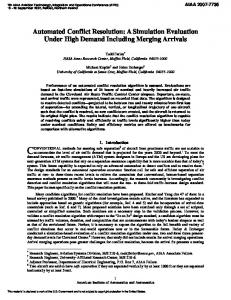
Fig. 2. Resolution trajectory must resolve both primary and two types of secondary conflicts constraints on range and altitude that may also cause the performance envelope to be exceeded. In the event a failure occurs, however, the TS sends an appropriate diagnostic message back to the RMG. The RMG responds by selecting the next-in-priority resolution maneuver and sends new trial resolution parameters to the TS for another attempt to synthesize a trajectory. When TS succeeds in generating a 4D trajectory, it sends the trajectory to the Conflict Detector (CD) to check for conflicts. Both ACES and CTAS contain software processes that detect conflicts by comparing the trial 4D resolution trajectory against the 4D trajectories of all other aircraft in the airspace of interest. A conflict check of the trial resolution trajectory is necessary for two reasons: 1. First, to verify that the trial resolution trajectory has successfully resolved the original (primary) conflict. Verification is necessary because the simplifications, approximations and rules of thumb used by the RMG can introduce significant differences between the trial resolution maneuver and the accurately computed 4D trajectory produced by TS. These differences can result in the primary conflict remaining unresolved in the trial resolution trajectory.
2. Second, to rule out the possible presence of secondary conflicts (which are illustrated in Fig. 2). A conflict caused by a third aircraft whose trajectory intersects the trajectory of the primary conflict downstream is referred to as a downstream secondary conflict. Downstream secondary conflicts are encountered more frequently as the time horizon for conflict detection or the density of traffic is increased. A conflict involving a fourth aircraft found along the trial resolution trajectory is referred to as a trial resolution secondary conflict. Trial resolution secondary conflicts can arise along any trial trajectory, since each resolution is designed to resolve only the primary conflict. If the trial resolution trajectory is free of conflicts for the specified resolution time horizon, the algorithm promotes the trial resolution trajectory to the status of acceptable resolution trajectory. The ground system can now uplink this trajectory to the conflict aircraft and, after receiving a “will comply” message back from the aircraft, update the data base of currently approved 4D trajectories for aircraft in the resolution airspace. If the trial resolution trajectory is found to have conflicts within the specified resolution time horizon, a fault message along with 4
AUTOMATED CONFLICT RESOLUTION FOR AIR TRAFFIC CONTROL
appropriate diagnostic information is sent back to the RMG, which will pick the next-in-priority trial resolution maneuver and send it to the TS for synthesizing another trial trajectory. This iterative process continues until either an acceptable resolution trajectory is found or the reservoir of available trial resolution maneuvers is exhausted. If no resolutions are found, the RMG has additional methods to extend the search for resolutions as described below. Two parameters in the RMG are used to exercise control over the resolution process and to search for additional resolutions. The first parameter is the resolution initiation time horizon (RIH) and the second is the conflict free time horizon (CFH). The RIH is defined as the time before the loss of separation is predicted to occur. It is the moment a conflict first becomes eligible for resolution. For conflicts predicted by the CD, the time to first loss of separation can range from immediately to a maximum of about 20 min. However, the further into the future the prediction is for first loss to occur, the more likely it is that the conflict will be a false alarm. Performance studies of conflict prediction algorithms have shown that if the predicted time to first loss is 8 min or less, the prediction accuracy is sufficient for the conflict to be considered for resolution [10]. Therefore, it is reasonable to set the value of RIH to 8 min , and thus defer resolutions for conflicts with a predicted time to first loss greater than 8 min. The CFH parameter specifies the time interval required to free the resolution trajectory of conflict and will be larger than the RIH. The larger the CFH that is chosen, however, the more difficult it becomes for the algorithm to find a resolution trajectory, because of the increased likelihood that multiple conflicts will have to be resolved. Conversely, the smaller the CFH that is chosen, the less likely it is that secondary conflicts are encountered, thus making it easier to find an acceptable resolution. In simulations of the resolution algorithm described later, a CFH value of 12 min resulted in acceptable performance. The software implementation of the algorithm allows the RIH and CFH parameters
to depend on the conflict type and other factors. Thus, for conflicts between arrivals converging to the same arrival fix, RIH and CFH are set to the same time, which is determined by the time the earliest aircraft is predicted to cross the arrival fix, but not exceeding a maximum of 20 min. This choice of time horizon allows arrival conflicts to be solved efficiently. If the RMG fails to resolve a conflict when the time to first loss falls below the RIH for the first time, the RMG will attempt another resolution when the time to first loss decreases a specified amount, typically 2 min. This process, referred to as deferral of resolution, is repeated in 2 min decrements until a resolution is found or until the time to first loss has decreased to between 1 and 2 min. If still no resolution is found, a final attempt to find a resolution is made by reducing the CFH to 5 min. In the rare circumstance that the algorithm fails to resolve a conflict at this final opportunity, the algorithm passes the conflict to a separate resolution process called TSAFE (as described in the references on the design of AAC [7]). TSAFE serves as a backup and safety net in case the primary resolution algorithm described here fails. 3 Resolution Aircraft and Maneuver Selector (RAMS) The resolution aircraft and maneuver selector (RAMS) is an element within the algorithm that gives strategic, top-level direction to the resolution process. Based on the characteristics of a particular conflict and on the application of rules and procedures coded into it, RAMS selects the preferred aircraft to perform the resolution and the initial preferred maneuver to be used to construct a trial resolution trajectory. Although RAMS is conceptually reminiscent of an expert system, its rules and procedures are derived not only from human experts such as controllers, but also from operational insights and analytical studies that have revealed the general characteristics of efficient resolution techniques. Rules and procedures used by controllers to resolve various types of conflicts provided an 5
HEINZ ERZBERGER
important starting point for the development of RAMS. However, as the development and evaluation of the algorithm evolved to include more complex traffic scenarios, conflict problems were encountered that could not be matched easily with the types of problems controllers typically solve. Complex problems arose primarily when traffic densities and resolution time horizons were substantially greater than those controllers had experience handling. Thus, it became necessary in the development of RAMS to augment the rules and procedures that controllers use with rules designed to handle these new classes of problems. The software was designed to allow for, and to simplify as much as possible, the process of modifying the RAMS rule base. The ability to easily modify and augment the rule base was an important design attribute for this system. It is likely that changing conditions in the airspace and different applications will require the software to be modified over time. From an input-output perspective, RAMS can be viewed as transforming the parameters and other attributes of a given conflict into a resolution strategy. However, the resolution strategy is not a single resolution procedure but rather a set of procedures that have been ordered into a preferred sequence of trial resolutions. The order of the sequence is determined by a combination of relevant controller preferences and by trajectory efficiency and operational considerations. Airspace user preferences are incorporated in the strategy by giving preference to maneuvers that minimize deviations from the original trajectory. Each procedure in the set specifies both the aircraft in the conflict pair that shall perform the trial resolution and the type of the resolution maneuver to be tried. Generally, each aircraft in the conflict pair is eligible to be selected, but in the current algorithm design, only one aircraft at a time is selected to perform the resolution maneuver. This rule excludes using cooperative resolution maneuvers where both aircraft maneuver and execute their maneuvers synchronously. Although in resolving certain types of conflicts, it is known that cooperative
resolutions can be more efficient than single aircraft resolutions, cooperative resolutions are more difficult to implement and, therefore, are not used here. However, nothing in the structure of the algorithm prevents them from being added at a later time. As described in the algorithm overview section, the first trial resolution strategy set specifies both the preferred aircraft and the preferred resolution maneuver for the given conflict. It is the aircraft and the maneuver that will be tried first to determine if the strategy solves the conflict. Resolution maneuvers farther down the preference option list are generally less desirable and will be tried only if the earlier and more desirable trial resolutions are rejected. The number of maneuvers in the set depends strongly on the particular characteristics of a conflict. Three types of maneuvers—changes in altitude, horizontal route, and speed—are used to construct resolution trajectories. In general, each resolution aircraft is eligible to perform any one of the three types of maneuvers. However, compound maneuvers—consisting of two or three types of maneuvers in the same resolution trajectory—are generally excluded in the current implementation of the algorithm. This exclusion notwithstanding, the algorithm does permit the use of horizontal maneuvers while an aircraft is climbing or descending at the time the maneuver is initiated. Although compound maneuvers could contribute flexibility and efficiency to the resolution process, they increase the operation’s complexity and are not justified at this time. If an operational need for compound maneuvers should arise in the future, the algorithm could easily be modified to accommodate them. The resolution process starts with RAMS matching a given conflict with one of the types listed in the first column of Table 1. It is noteworthy to observe that 8 of the 12 conflict types listed in the table involve at least one arrival aircraft. An aircraft is classified as an arrival in this analysis if it is either within 200 nmi or less than 20 min from its arrival fix. An
6
AUTOMATED CONFLICT RESOLUTION FOR AIR TRAFFIC CONTROL
Table 1: List of conflict types and corresponding preferred A/C and maneuver types Conflict Type Cruise vs. cruise, crossing angle large Cruise vs. cruise; converging, crossing angle small or in trail Cruise vs. climb Cruise/Cruising arrival more than 5 min from top of descent Cruise/Descending arrival Climb/Climb
Climb/Cruising Arrival
Climb/Descending Arrival Cruising Arrival / Cruising Arrival (same arrival fix)
Cruising Arrival /Descending Arrival (same arrival fix) Descending Arrival / Descending Arrival (same arrival fix) Arrival vs. arrival (different arrival fixes)
Preferred A/C and Maneuver Sequence A/C farthest from airspace boundary or TOD: Step alt.; other A/C: Step alt., min sep. turn if eligible, path stretch, speed Faster A/C at First Loss: Step alt., path stretch, speed; Slower A/C at first loss: Same maneuver sequence as above Climbing A/C: Temp alt.; Cruise A/C: Step alt., path stretch Arrival A/C: Temp alt.; Cruise A/C: Step alt., path stretch Cruise A/C: Step alt., path stretch; Arrival A/C: Path stretch Lower A/C: Temp. alt.; Higher A/C: Temp. alt.; Lower A/C: Path stretch Climbing A/C: Temp. alt.; Arrival A/C: Temp. alt.; Climbing A/C: Path stretch Climbing A/C: Temp. alt., path stretch; Arrival A/C: Path stretch Leading A/C at Arrival Fix: Speed increase in cruise, faster descent speed profile; Trailing A/C at Arrival Fix: Speed Reduction in cruise, slower descent speed profile Cruising Arrival: Speed, speed profile, temp. alt., path stretch; Descending Arrival: Path stretch Trailing A/C at Arrival Fix: Path stretch; Leading A/C at Arrival Fix: Path stretch A/C farthest from arrival fix or in cruise: Temp. alt., path stretch
arrival fix is defined as the entry point into the terminal area and is typically located about 30 nmi from the airport. Any conflict pair that includes an arrival requires special resolution strategies. The subclass of arrival vs. arrival conflicts converging to the same arrival fix are generally the most difficult to resolve. The types that are coded in RAMS also include types that have been left out of the table because they are encountered infrequently. The second column shows the preferred initial choice for the maneuver aircraft (in bold type) and corresponding resolution maneuver. The second and third preferences for the resolution maneuvers, if applicable, are also given in the table for some cases. The transition to the non-preferred aircraft and the corresponding sequence of trial maneuvers are given for a few important conflict types. This
table is a simplified representation of the logic coded into RAMS. An examination of the preferences listed in the second column of Table 1 reveals that for non-arrival conflicts, altitude changes are favored over horizontal and speed changes as the preferred initial choice for resolution maneuvers. This strategy is referred to as an altitude-first resolver as distinguished from a horizontal-first resolver. A comparison of average delays obtained for these two strategies in fast-time simulations revealed a significant advantage in delay reduction for the altitudefirst resolver. Thus, whenever circumstances permit, all feasible altitude maneuvers will by tried first for the preferred aircraft and then for the non-preferred aircraft before horizontal maneuvers are tried for either aircraft. Resolution strategies vary considerably among controllers, with some favoring horizontal and 7
HEINZ ERZBERGER
some favoring vertical resolutions. An advantage of an automated algorithm is the ability to implement a strategy that provides consistent efficiency benefits. An exception to the altitude-first rule is made for encounters where one of the conflict aircraft is a descending arrival. For such encounters, a horizontal maneuver referred to as a path stretch is used (this is explained in the next section). Finally, it should be mentioned that the software gives users the option of specifying either of the two strategies. The preferred resolution maneuvers used to resolve arrival vs. arrival conflicts converging onto a common fix were chosen to be similar to the proposed trajectories used to control arrival traffic onto a metering fix. The table distinguishes between several types of arrival vs. arrival conflicts. If both arrivals are in cruise, then speed changes in cruise and/or in descent are the preferred maneuvers. For these cases, the sequence order at the arrival fix helps determine the preferred maneuver aircraft. If only one aircraft is in cruise at the time resolution is initiated, only the cruising aircraft is eligible for speed changes. For an aircraft in descent, horizontal maneuvers are the preferred, and only, choice. Since large speed changes may be difficult or impossible for an aircraft to perform while descending to an arrival fix, the algorithm excludes the use of speed changes for an aircraft in descent. However, the option of permitting small speed changes during descent could easily be added to the logic if necessary. An automated method for controlling arrival traffic converging to a metering fix will eventually require a system that integrates arrival scheduling, descent profile management, and conflict resolution. The method for resolving arrival conflicts implemented here is thus limited in scope and performance, but it provides a necessary building block for a future integrated design. Another important characteristic built into the strategy for generating the sequence of trial maneuvers is the principle of minimizing deviation from the original trajectory. This means that the sequence of preferred trial maneuvers, whether they involve changes in
altitude, horizontal position, or speed, generally starts with a trial maneuver that deviates the least from the original trajectory. For each additional trial that is required to resolve the conflict, the deviation from the previously tried maneuver is increased by the smallest usable increment. This principle contributes to the overall efficiency and operational acceptability of the resolutions by ensuring that the maneuvers will not introduce unnecessarily high delays or large deviations from the original flight path unless they are required to solve the conflict. (Additional details for choosing the trajectories that incorporate this principle will be given in the next section.) In order to provide insight into the logic in RAMS, the entire set of trial maneuvers, as well as all transitions from one maneuver aircraft to the alternate aircraft, are shown in Tables 2 and 3 for two conflict types. They are cruise vs. cruise (not in trail) corresponding to the first conflict type listed in Table 1 and cruising arrival vs. cruising arrival corresponding to the ninth type. The maneuver aircraft preference orders and associated trial maneuvers for these two types were chosen because they illustrate the widest difference in the resolution strategy among any of the conflict types. The search for an acceptable resolution trajectory begins by evaluating each of the trial altitude maneuvers for A/C A in the order shown. If an acceptable resolution trajectory is not found, then the search is repeated for A/C B. This process continues by moving down the rows of Table 2, concluding with the set of speed changes for A/C B. The search is terminated for the first trial maneuver encountered that meets the requirements for an acceptable resolution trajectory. In the worst case, this process could require the generation of up to 86 trial trajectories by the 4D trajectory synthesizer. For cruise vs. cruise conflicts or any other type that includes at least one nonarrival aircraft the iteration process generally succeeds in fewer than 5 trials. As will be seen in a later section where performance results are discussed, the average number of trials begins to increase when secondary conflicts are encountered more 8
AUTOMATED CONFLICT RESOLUTION FOR AIR TRAFFIC CONTROL
Table 2. Total maneuver sequences for cruise vs. cruise conflicts (not in trail) Maneuver Type of trial maneuver A/C A/C A Increase altitude up to two flight levels above cruise level Decrease altitude up to 3 flight levels below cruise level A/C B Increase altitude up to two flight levels Decrease altitude up to 3 flight levels A/C A Horizontal maneuvers (path stretch): 4 levels of delays, 2 turn directions, 4 vector angles, tried in sequence A/C B Horizontal maneuvers (path stretch): 3 time delay options, 2 turn directions, 4 vector angles tried in sequence A/C A
A/C B
# of options 5
Table 3. Resolution aircraft and trial maneuver sequence for cruising arrival vs. cruising arrival conflicts Maneuver A/C A/C A A/C B
5
A/C A A/C B
Up to 32
A/C B A/C A
Up to 32
Speed increase, up to 3 6 increments; speed decrease, up to 3 decrements Speed increase, up to 3 6 increments; speed decrease, up to 3 decrements
frequently. That occurs only at the highest traffic densities tested in simulation. For the arrival vs. arrival conflict shown in Table 3, the initial (preferred) maneuver aircraft, designated A/C A, is the one predicted to first cross the arrival fix. Conflicts near an arrival fix are often caused by a phenomenon referred to as compression, which occurs when a faster trailing aircraft is decelerating to specified crossing speed at the arrival fix. A series of speed increases are tried for this leading aircraft. A desirable solution for this type of conflict is to increase cruise speed for the lead aircraft briefly during cruise flight prior to the top of descent because such a maneuver will avoid the need to delay the trailing aircraft. It is well known from the study of arrival traffic management that speeding up a lead aircraft during an arrival rush often has a beneficial domino effect in reducing delays for all trailing aircraft converging on the same arrival fix. If a speed up during the last phase
A/C B
A/C A
Type of trial maneuver
# of options Increase cruise speed in up to 3 3 increments Decrease cruise speed in up to 4 4 decrements Increase cruise/descent speed 3 profile in up to 3 increments Decrease cruise/descent speed 4 profile in up to 4 decrements Decrease cruise altitude in up 10 to 10 flight level decrements Decrease cruise altitude in up 10 to 10 flight level decrements Horizontal maneuvers (path Up to 32 stretch): 4 increments of delay, 2 turn directions, 4 vector angles, tried in sequence Horizontal maneuvers (path Up to 32 stretch): 4 increments of delay, 2 turn directions, 4 vector angles tried in sequence
of cruise flight does not solve the conflict, a coordinated increase in both the cruise speed and descent speed profile is tried for the lead aircraft. If these speed-up maneuvers for the lead aircraft do not succeed, the next set of chosen maneuvers is a series of speed reductions for the trailing aircraft, A/C B. These speed-change maneuvers are followed by altitude reductions and finally by horizontal maneuvers for each conflict aircraft in turn. For arrival vs. arrival conflicts the number of trials that are evaluated before finding a successful resolution can approach the maximum number of available trial maneuvers. A large number of trials can occur when the algorithm is exposed to traffic rates that overload an arrival fix. In order to reduce the number of trial resolution trajectories generated by TS, the algorithm includes logic that analyzes the causes of failure of a trial resolution trajectory and then bypasses or eliminates certain types of untested trial maneuvers. For example, if a conflict is detected during the climb segment of an altitude change resolution maneuver, the logic eliminates all trial flight levels above the 9
HEINZ ERZBERGER
flight level where the trial maneuver conflict was detected, as will be explained further in the next section. The RAMS software has been designed to make enhancing the resolution algorithm as simple as possible. For example, instead of accepting the first successful resolution, as is done in the current implementation, the trial resolution process could be continued to find additional successful resolutions for specified maneuver types. From these, the most efficient resolution could be implemented. Such an enhancement is under consideration. 4 Resolution Maneuver Generator (RMG) The RMG transforms any trial maneuver provided by RAMS into a specification that defines a unique 4D trajectory. The specifications can also be interpreted as representing a highly simplified trajectory, which often lacks the detailed structure and aircraft performance model adaptation required for a pilot or on-board flight management system to be able to fly it. The precise content of the specifications is determined by the set of parameters, logical states, and coordinates that a 4D trajectory synthesis algorithm requires in order to compute a 4D trajectory, which is adapted to a specified aircraft and atmospheric model. The specifications generated by the RMG conform to the input parameters required by the Trajectory Synthesizer (TS) in the Center-TRACON Automation System (CTAS) as well as by ACES. The TS in CTAS is a software component in the Traffic Management Advisor, a subset of the suite of automation tools in CTAS. This fact is relevant here, since the Traffic Management Advisor, including the TS, is deployed and in operational use by FAA at many en route centers. TS may therefore offer an opportunity for reuse in the future by an automated conflict resolver deployed at en route centers. The specifications generated by RMG are also sufficient to serve as input to advanced onboard flight management systems, as well as 4D trajectory planning systems developed elsewhere.
Earlier discussions referred to changes in altitude, horizontal route, and speed profile as the three types of maneuvers used in the construction of resolution trajectories. The next step is to give a precise definition of these resolution maneuvers and to describe how they are calculated. 4.1 Step altitude trial maneuvers for maneuvering aircraft in cruise flight A step altitude resolution maneuver for an aircraft in cruise flight is defined by two parameters. The first specifies the flight level, hstep , at which the aircraft performing the resolution maneuver is assigned to fly for a period of time. The flight level hstep may be a step up or a step down of one or more flight levels relative to the current cruise flight level, hc . The second parameter specifies the time, tr , at which the aircraft initiates its return to the assigned cruise flight level, hc . The initiation time includes a short delay, typically 0.5 min, to allow for pilot reaction time. Altitude changes from hc to hstep and back to hc are calculated to be performed at altitude rates that are nominally used for such maneuvers by the resolution aircraft. Figure 3a shows plots of these step altitude maneuvers as a function of time. The order in which they are tried is also shown in the figure. The altitude steps are changed in 1,000 ft. increments or decrements, equaling the required altitude separation between adjacent flight levels. If, however, the nonmaneuvering aircraft is in a state of climb or descent at the point of first loss of separation, the minimum step change in altitude is increased to 2 flight levels or 2,000 ft. The increased separation margin provides a buffer to help immunize the resolution maneuver against uncertainties in the execution of trajectories that include altitude changes. The trial resolutions proceed from 2 step ups to 3 step downs in altitude. Step ups are preferred because of fuel efficiency considerations. 10
AUTOMATED CONFLICT RESOLUTION FOR AIR TRAFFIC CONTROL
Fig. 3. Trial altitude resolutions for maneuvering aircraft in (a) cruise and in (b) climbing flight Before the trial resolution is accepted and sent to TS, RMG checks its ability to reach the higher flight level. RMG also checks for other constraint violations, including those due to high levels of turbulence and airspace boundaries. If a constraint violation is detected, RMG selects the next step altitude in order and repeats the constraint violation check. This process is repeated until an acceptable step altitude is found. If the choices for step altitude maneuvers become exhausted, RMG switches to the next type of resolution maneuver specified by RAMS. To complete the specification of a step altitude trial maneuver, a method for assigning a value to tr must be provided. The method implemented in RMG sets tr equal to the sum of tcl , which is defined as the time where
minimum separation is first reestablished in the original conflict encounter, and a buffer time increment, typically chosen as 1 min. This method of calculating tr provides only a rough estimate, which may need to be revised as described below. It should be noted here that the interval of time during which loss of separation is predicted to occur is the difference between tcl and t fl , where the latter quantity denotes the time where separation is first lost. Both tcl and t fl are provided to RMG by the Conflict Detector. The parameter calculated above for a step altitude maneuver together with the parameters describing the current state of the maneuver aircraft (position coordinates, speed, and course) and its horizontal route are sufficient for TS to 11
HEINZ ERZBERGER
calculate a trial 4D resolution trajectory. If the conflict check of the trial trajectory generated by TS indicates that the primary conflict was not cleared, RMG uses the diagnostic information provided by the Conflict Detector to determine if an increase in tr could clear the conflict using the same step altitude maneuver. An increase in tr is called for if the first loss time with the primary conflict aircraft occurs after tr .Such a condition indicates that the maneuver aircraft returned too early to its original cruise altitude to clear the conflict. In that case, tr is recomputed using the value of tcl obtained for the trial maneuver. This procedure for revising tr may be repeated a second time if necessary, but it is subject to a maximum time the aircraft can stay at the step altitude flight level. If the primary or a secondary conflict is detected in the initial altitude change segment of a step altitude maneuver, then all other step altitude maneuvers in the same direction of altitude change greater than the step change in the current trial step maneuver will also contain these conflicts. Therefore, RMG will select the next trial step maneuver from available step altitudes in the opposite altitude change direction. Thus, the information obtained from trial resolution failures are used by RMG to bypass some step altitude maneuvers, thereby expediting the process of finding a successful step altitude resolution trajectory. 4.2 Temporary altitude resolutions during climb to cruise altitude In this case the aircraft assigned by RAMS to perform the altitude resolution maneuver is currently climbing toward its assigned cruise altitude. The time of first loss with the conflict aircraft may occur during the climb segment or after the aircraft has leveled out at its cruise altitude. The specification of the parameters for the trial resolution trajectory is the same for both situations. However, a conflict occurring during climb was selected to represent this class of maneuvers, because this type shows
important differences from the cruise case described above. A temporary altitude maneuver for an aircraft in climb is defined by two parameters. Similar to the previous case, the first specifies the flight level, htemp , at which the maneuvering aircraft must level out (also referred to as the temporary altitude level). Only flight levels above the current altitude of the climbing aircraft and below the flight level of the altitude where first loss occurs are eligible to be chosen for htemp . If the non-maneuvering conflict aircraft is in cruise at the point of conflict, the first and preferred temporary altitude flight level is chosen to be the first flight level below the altitude where first loss of separation is predicted to occur. If the non-maneuvering conflict aircraft is either climbing or descending at the first loss altitude, as shown in Fig. 3b, the first trial step altitude flight level chosen must be a minimum of one flight level below the flight level immediately above the level at which the loss of separation occurs. An additional flight level of separation would provide an even higher altitude margin to insure against adverse unpredictable variations in altitude rate changes of either aircraft. The need for the additional level will depend on the accuracy of climb/descent profile prediction. As shown in Fig. 3b, the lowest trial step altitude level (4th trial) is separated from the current altitude of the maneuvering aircraft by an extra flight level. This altitude margin gives the pilot of the maneuvering aircraft sufficient lead time to perform the level-out maneuver. In an attempt to avoid having the maneuvering aircraft level out at a temporary altitude, if at all possible, a reduced climb rate option is tried under the following condition. After a successful resolution trajectory at a temporary altitude has already been found for a conflict in climb, a trial maneuver specifying a reduced climb rate ( for example at 50% of standard climb rate) to fly to the cruise altitude is sent to TS/conflict detector for evaluation. This option is tried only if the conflict occurs at an altitude within about 3 flight levels of the maneuvering aircraft’s final cruise altitude. 12
AUTOMATED CONFLICT RESOLUTION FOR AIR TRAFFIC CONTROL
Controllers occasionally use the reduced climb rate technique because it lessens the workload for both controllers and pilots. The second parameter that defines the temporary altitude maneuver is the time, tc1 , at which the maneuvering aircraft begins its climb to capture the assigned flight level from the 1st trial temporary altitude level. The time to resume climb is shown in Fig. 3b by the dashed vertical line. The resume climb segments for the four trial maneuvers are slightly separated for clarity. Analogous to the step altitude maneuver case, tc1 for the 1st temporary altitude maneuver is determined to be the sum of tcl and a buffer time interval, typically chosen as 1 min. For trial temporary altitude levels lower than the 1st, a simple relation is used to calculate tcn , defined as the time to resume climb from the nth trial temporary altitude level. By using an estimate of the climb rate, hdot , together with the altitude difference between the 1st and nth trial temporary altitude levels, this time is calculated as where tcn = tc1 − ( htemp1 − htempn ) / hdot , htemp1 and htempn are the altitudes at the 1st and nth
trial temporary altitude flight levels. Determining tcn by this procedure maintains the length of time the maneuvering aircraft spends at the different temporary altitude level relatively constant. The effect of this procedure can be seen in Fig. 3b for the 2nd, 3rd and 4th trial temporary altitude. The specification of the temporary flight level and time to resume climb, together with the current state of the maneuvering aircraft, provide sufficient information for TS to generate the trial temporary altitude resolution trajectory. Analogous to the step altitude maneuver case, the conflict information obtained from analysis of the trajectory generated by TS for the 1st trial temporary altitude maneuver provides guidance on how to choose the next trial maneuver. If a conflict, which may be either the original or a secondary, is detected
during the resume climb to cruise segment or in cruise, the same temporary altitude can be retried after replacing tc1 with a larger value, which is simply the new value of tc1 plus a buffer interval. However, retrial of the same temporary altitude is subject to the updated tc1 being less than a specified maximum value, typically 10 min. If any type of conflict is detected at the previously tried temporary altitude flight level, then the next available temporary altitude level must be selected for trial resolution. RMG also generates temporary altitude resolution maneuvers for conflicts in cruise or descent between certain qualifying arrival and non-arrival aircraft as specified by RAMS. The approach used to determine the trial maneuver parameters for this case is somewhat simpler than the climb case and is therefore not described here. 4.3 Horizontal trial resolution maneuvers The template for the construction of all horizontal resolution maneuvers generated in this algorithm is illustrated by the example resolution maneuvers shown in Fig. 2. It consists of a resolution segment and a return segment, both of which are fixed in plan view for climbing, descending or level flight aircraft by the specification of two pairs of coordinates. The first coordinate pair establishes the location of the auxiliary waypoint that defines the end of the resolution vector segment, and the second defines the location of the waypoint where the return segment connects to the original flight plan route. This section will outline the procedures and analytical techniques implemented in the RMG software for calculating these coordinate pairs to resolve a given conflict. There are two distinct ways to conceptualize the problem of resolving conflicts by horizontal maneuvers: one in the spatial, and one in the time domain. Each leads to fundamentally different analytical formulations and algorithms for calculating resolution maneuvers. 13
HEINZ ERZBERGER
Fig. 4. Resolutions for specified separation distance (in A/C A relative velocity coordinates); example shown is drawn approximately to scale for the given parameters Initially, only the spatial domain algorithm was implemented in RMG because it theoretically produces resolution maneuvers that minimize delay for a specified separation, if the conditions assumed in the derivation of the algorithm are met. However, after simulation tests revealed that the required conditions were often violated by the type of conflicts encountered, thus resulting in a high rate of failed trial resolutions, it became necessary to also implement the time domain algorithm. Simulations have shown that the time domain algorithm is generally more successful in producing resolutions for the type of conflict scenarios encountered in en route airspace, although this algorithm cannot claim to produce optimal resolutions. Each algorithm is now used for specific types of conflicts, as will be explained later.
4.3.1 Spatial Domain: Specified separation resolution algorithm The key to the spatial domain formulation is to transform the conflict encounter into relative position and velocity coordinates for one of the two conflict aircraft. Let A and B designate the conflict aircraft and let their velocities be Va and Vb . The crossing angle of the encounter in a fixed earth coordinate system is θ . The location of A is chosen as the origin of the relative coordinate system with the y axis aligned in the direction of Va . The two velocity vectors and the relative position coordinates ( xb , yb ) of B define the parameters of the conflict. Figure 4 illustrates the geometric relationships of an encounter between two aircraft in the relative coordinate system.
14
AUTOMATED CONFLICT RESOLUTION FOR AIR TRAFFIC CONTROL
The figure also gives the solution for an example encounter, which will be discussed shortly. In the relative coordinate system, A is stationary and, therefore, observes B moving along the direction of the relative velocity of B with respect to A, defined as Vr . The flight path for B in this coordinate system lies along the extension of its relative velocity vector, starting at the location of B. After choosing convenient scales for distance and speed, any conflict encounter can be accurately constructed to scale by using only a compass, a protractor, and marked ruler. This construction is carried out for the example conflict parameters given in Fig. 4. The construction involves adding and subtracting the vector velocities of A and B by well-known graphical procedures. The construction shows the point of minimum separation as the point of tangency of a circle with center at A and the extension of the line along the relative velocity vector, Vr , emanating from the position of B. The length of the radius of the separation circle gives the miss distance, which is 2.2 nmi for the example in Fig. 4. This distance is less than the required minimum separation distance, thus indicating that a loss of separation will occur. The time to first loss can also be determined from this construction by measuring the distance from B to the interception point with the separation circle and dividing it by the absolute value of the relative velocity vector Vr . Its length can be measured with a marked ruler calibrated in units of the chosen speed scale. For the example parameters in fig. 4 the time to first loss is 2 min, which is near the lower limit of usability of this resolution method. An extension of the graphical method described above can be used to construct resolution trajectories with required minimum separation. It can be shown graphically that the slower of the two aircraft, assumed here to be B, can have up to 4 different directions of flight (resolution course changes) that will cause the aircraft to fly along one or the other of the two directed line segments that start at the position
of B and that are tangent to the required separation circle, as illustrated in Fig. 4. However, only the two course directions—one to the left and one to the right of the current course of B—that require the smaller angular changes in course relative to the current course of B are potentially usable resolutions. The two usable resolution course changes of B are designed as φbf and φbb , which, respectively, produce front side and back side resolution maneuvers relative to A, as shown in Fig. 4. Because the relative velocities corresponding to the two course changes are generally different, the times to fly to the tangency points of the required separation circle will also differ, resulting in different amounts of delay. The faster aircraft (assumed to be A) has exactly two course change directions—one producing a front side and the other a back side resolution relative to B—that will become tangent to the separation circle of B (not shown in the Fig. 4 to reduce clutter). The graphical construction procedure outlined above gives an insightful geometric representation of the spatial resolution method. A closed-form analytical solution that is the algebraic analog of the graphical solution has been implemented in RMG software. It generates the four usable course changes for the two aircraft (as well as the two non-usable ones, which are discarded), and generates the coordinates and times of tangency to the required separation circle. The approach used here formed the basis for a parametric study of strategic horizontal and speed resolution techniques [11]. Variations of this closed-form solution have been derived in papers published by several authors [4]-[6]. After the maneuvering aircraft, A or B, passes the tangency point to the separation circle, it is necessary to determine the earliest time it can change course to intercept the original flight path at a specified waypoint, referred to as the return waypoint. The time to turn and the course change must be chosen so that the return segment does not intercept the separation circle. The earliest time to turn for a given course change is the time that results in a path that also becomes tangent to the separation 15
HEINZ ERZBERGER
circle, as shown in Fig. 4 by the line labeled “return path.” The position along the resolution path that achieves the tangency condition determines the coordinates of the auxiliary waypoint and establishes the turn back time. An analytical expression for the coordinates of the auxiliary waypoint that produces the double tangency condition was derived in an earlier study [11] and a variation of that approach is used in the algorithm here. The algorithm implemented in RMG calculates the auxiliary waypoint coordinates for the four usable resolutions and estimates the total time to fly each trajectory to the turn back waypoint. The set of up to four feasible resolutions is then ordered by time delay. If the return waypoint is sufficiently far away from the auxiliary (turn-back) waypoint, the delay, δ ti , of the resolution trajectory can be approximated by the relation δ ti = ttbi (1 − cos φi ) , where ttbi denotes the turn back time corresponding to the course change angle φi of the i th resolution maneuver. A more general expression for the delay can be found in [11]. The resolution trajectory that gives the shortest delay is ranked first in the set. The four resolution course change angles and corresponding delays are given in Fig. 4 for an example encounter. A right turn by aircraft A is ranked first because it gives the shortest delay. The next best resolution is a right turn by aircraft B. The last two solutions switch aircraft and have much larger and nearly equal delays. RMG initially sends the first-in-order maneuver and corresponding maneuver aircraft to TS for generating the trial resolution trajectory. If this trajectory is not conflict free, RMG will send the next-in-order maneuver to TS. This process continues either until an acceptable resolution is found or until the available maneuver choices are exhausted. If the first trajectory in the resolution maneuver set produces a successful resolution, and if the assumptions made in the development of the algorithm describe above were to be exactly satisfied, then the resulting trajectory qualifies to be called an “optimum resolution
maneuver” in the sense that it minimizes the delay. Note that the solution is optimal with respect to both the selection of the maneuver and the choice of the maneuver aircraft. Considering the significance of an optimal solution for the critical problem of conflict resolution, it is important that the required assumptions are stated precisely for the solution to be considered optimum. First, both aircraft are assumed to be flying along straight lines at constant speeds and heading relative to an earthfixed coordinate system. They must maintain these flight conditions from their current positions to points well past the region where loss of separation occurs. This implies that they are tracking straight flight segments before and after the encounter. The assumption of constant ground speed implies both aircraft are maintaining constant altitude during the same period. Second, the resolution course changes are assumed to be made instantaneously (no turn dynamics are included) with the speeds of both aircraft remaining constant during the maneuver. This assumption also implies that the wind field is zero everywhere, since the presence of winds would cause the ground speeds to change as the aircraft changes course in executing a resolution course change. Any violation of these assumptions not only invalidates the claim of optimality for the resolution trajectory but also may cause loss of separation. The algorithm attempts to compensate for a failure to obey these assumptions by adding a buffer distance of 2 nmi to the required minimum separation distance of 5 nmi While this buffer does reduce the brittleness of the resolution trajectories, it does so at the cost of additional delay. In order to provide additional resolution options for this method, another set of up to four trial maneuvers is generated by choosing an even larger required separation distance of 10 nmi. All the solutions for this separation distance will have significantly more delay. These solutions are tried only if secondary conflicts are encountered for all of the available solutions computed for the smaller separation distance. 16
AUTOMATED CONFLICT RESOLUTION FOR AIR TRAFFIC CONTROL
4.3.2 Time Domain: Specified delay path stretch resolution algorithm This method of constructing horizontal resolution maneuvers is rooted in the concept of time shifting. In this concept, a conflict occurs in the event that two aircraft have 4D coordinates that fall within a specified 4D conflict volume at some future time. The time shift method hypothesizes that for either aircraft any trajectory change that produces a sufficient time shift in the neighborhood of the conflict point may potentially prevent this event from occurring. Because there are infinite ways to
Fig. 5. Path stretch vector resolutions for specified delay construct trajectories that achieve a specified time shift at a specified spatial position, the designer of an algorithm for time shifting has wide flexibility to define a set of trajectories that are operationally acceptable. The defined set needs only to generate time shifts with sufficient range. Unlike the spatial domain method, the time shift method does not impose special conditions on the characteristics of the original trajectories responsible for the conflict. The time shift method can also be used to generate trajectories that cross arrival fixes at a specified time. This capability is needed for arrival metering. These benefits are balanced by some disadvantages. First, while the trajectories achieve a specified time shift, they do not guarantee that a specified amount of separation
distance or altitude will be achieved between the conflict aircraft. Thus, this indirect approach cannot guarantee that any specified time shift will resolve the conflict. Moreover, when a time shift does solve the conflict, the separation achieved may be greater than is needed or desired. Second, even a time-shifted trajectory that resolves the primary conflict at the original location of the conflict may put the same pair of aircraft back into conflict at a downstream location. This can occur in trajectories containing dogleg segments with multiple crossing points. Such situations are rare but have been observed in actual flight plans. To mitigate these disadvantages and to correct for resolution failures, the time shift method depends critically on the iteration loop between the trial time shift maneuver generator in RMG and TS and its associated conflict detector. The time shift method has been found to be essential for resolving conflicts between descending arrivals on converging routes when the conflicts are predicted to occur close to the arrival fix. Such a scenario is illustrated in Fig. 5, which will be used to derive the basic analytical relations for the method. In the example shown, RAMS has selected A to be the maneuver aircraft, because it is predicted to trail aircraft B at the time B crosses the arrival fix. Let Tr denote the time for the chosen maneuver aircraft to fly from Ps to the return waypoint at Pr along its current arrival route. The location of the return waypoint along the original flight path is not critical for the time shift method. It is nominally located at a point two to three times as far as the conflict point is from the maneuvering aircraft. However, it is also acceptable to locate Pr close to the conflict point, as illustrated in Fig. 5. Locating Pr near the conflict point is necessary when the conflict occurs close to the arrival fix, as illustrated in Fig. 5. Pr can also be located a short distance in front of the conflict point. Ps denotes the start of the time shift maneuver, henceforth referred to as a path stretch. Let ΔT denote the delay to be provided 17
HEINZ ERZBERGER
by the path stretch maneuver. For this type of arrival conflict, ΔT would initially be set to about 1 min. Then the delayed arrival time of A at Pr is simply Tps = Tr + ΔT . Let Dsr be the length of the path from Ps to Pr , measured along the current arrival route. The average ground speed along this path, Vag , is given by Vag = Dsr / Tr . Let R1 denote the direct route
from Ps to Pr . An estimate of the time, TR1 , for A to fly from Ps to Pr via R1 is given by R1 / Vag . This estimate is based on the assumption that if A were to follow R1 it would fly essentially the same speed profile as it planned to fly along its longer original route. The length of the R1 route and the time to fly it are needed as a reference for computing the path stretch maneuver. Using R1 instead of the original arrival route as the reference route has the advantage of making the calculation of the path stretch maneuver independent of the often complex geometry of the original route. In some circumstances the direct route R1 is also selected as a trial maneuver for resolving a conflict. This maneuver gives a negative delay that is interpreted as a time saving. The difference in time between flying the original longer route and the R1 route must be added to the specified delay to determine a corrected path stretch delay measured relative to the time to fly the shorter R1 route. The corrected delay, ΔTc , is given by the relation ΔTc = ΔT + Tr − TR1 . The corrected delay can now be converted into an equivalent increment in path length, δ ps , relative to the length of δ ps = ΔTc ⋅ Vag .
R1
as follows:
Any placement of Paux that increases the path length between Ps and Pr along the twopath stretch segments by an amount δ ps is a candidate for an acceptable solution. An expression for δ ps can be written in terms of variables defined in Fig. 5:
δ ps = Rv + Rr − R1 (1) From the geometry of the maneuver shown in Fig. 5, the variables defining the maneuver are related by the law of cosines for triangles as follows: Rr 2 = Rv 2 + R12 − 2 Rv R1 cosψ v (2) where ψ v is defined as the vector angle for the maneuver, measured relative to the direction of the R1 route. The current course of the maneuvering aircraft, measured relative to the direction of R1 , is defined as ψ A . Thus, ψ v must be corrected by an amount ψ A in order to obtain the change in course required for A to fly along the direction of the resolution vector. These relationships are illustrated in Fig. 5. By using eq. (1) to eliminate Rr by substitution in eq. (2), the length of Rv can be expressed as a function of the variables defining the maneuver: R1 + δ ps / 2 Rv = (3) R 1 + 1 (1 − cosψ v )
δ ps
Since R1 is fixed by the location of the return waypoint and δ ps is known from an earlier expression, Rv becomes a function only of the path stretch vector angleψ v . When plotted in polar coordinates, Rv as a function of ψ v sweeps out an ellipse, with Ps and Pr at the foci. The locus of points on the ellipse defines all possible path stretch maneuvers for a specified delay. By changing δ ps in increments, a set of nested ellipses is generated. Figure 6 shows two example ellipses and several example path stretch vectors and their return paths. The area within each ellipse is seen to be flooded with a continuum of maneuvers ranging from small turns to large turns. This dense maneuver set gives the algorithm many alternative maneuver choices that are useful in helping to resolve secondary conflicts detected in trial maneuvers. However, not all vector angles provide usable path stretch maneuvers. To increase the acceptability of the maneuvers, 18
AUTOMATED CONFLICT RESOLUTION FOR AIR TRAFFIC CONTROL
Fig. 6. Envelope of path stretch vectors for two values of delay, drawn approximately to scale for R1 = 150 nmi and Vg = 300 kn the vector angles must be limited to about 60 degrees relative to the course of R1 . Furthermore, in the tradeoff between course changes at the start and end of the maneuver, it is operationally preferred for the course change angle at the return waypoint, Pr , to be the smaller of the two. The smaller angle helps to ensue a smooth merge-back maneuver to the original path at Pr . Implementation of this preference requires the vector angle to be no less than the value that produces a symmetric path stretch for any given value of R1 and δ ps . A symmetric path stretch is defined as having the aux. waypoint lie on the bisecting symmetry line of the ellipse, as illustrated in Fig. 6. By setting Rr = Rv in eq. 1 and using the resulting equation to eliminate Rv from eq. 3, an expression for the symmetric path stretch angle, ψ vs , is obtained:
ψ vs = cos −1
R1 R1 + δ ps
(4)
If ψ vs is larger than the maximum allowed angle for given R1 and δ ps , no path stretch solution exists. In that case, the algorithm
attempts to increase R1 by moving the return waypoint further downstream. Equation 3 allows a specified value of delay to be achieved with a continuum of vector angles, as long as the angles fall within the prescribed range. This freedom can be used to pre-select an operationally acceptable set of vector angles. The set consisting of 15, 30, 45, and 60 degrees has been found to be adequate. For each specified time delay, the first trial path stretch maneuver always starts with the smallest vector angle from this set that is larger than the symmetric vector angle obtained from eq. 4. The higher angles in the set are used in subsequent trials if needed to solve the conflict. It should be noted that for each choice of vector angle, both left and right turn directions are tried before the next higher angle is chosen. Since path stretch maneuvers generated by this method are designed to achieve a time shift at a specified point, but not a specified separation in distance or altitude at the conflict point, the calculation of a 4D trajectory corresponding to the trial maneuver is an indispensable step in determining whether the trial maneuver has solved the conflict. Analysis of the trial 4D trajectory to the conflict detector provides diagnostic information back to RMG, which uses it to select the next trial maneuver 19
HEINZ ERZBERGER
Fig. 7. Horizontal resolution order selection
when necessary. If conflict detection predicts that loss of separation with the primary conflict aircraft will occur in the vector segment, Rv , then RMG selects the next higher vector angle for the next trial maneuver. If the primary or a secondary conflict is detected in the return segment, Rr then the time shift may be insufficient and a larger time delay will be selected. Additional rules, not described here, decide when the direction of the vector turn should be switched. 4.3.3 Integration of spatial and time domain horizontal resolutions Because each resolution method has strengths and weakness that depend on the characteristics
of the conflict to be resolved, both methods have been incorporated in the resolution algorithm. In order to make best use of the two methods, the algorithm first analyzes the flight plans and associated trajectories of the conflict aircraft to determine which of the two methods should be given first opportunity in solving the conflict. The flow chart for this analysis is summarized in Fig. 7. The selection decision is based on an analysis of the current flight plans and their associated trajectories. If all the conditions given in the top decision diamond are true, then the spatial separation vector method of resolution is tried first. This method has up to 8 maneuver options to find a successful resolution. If none are found, the conflict is 20
AUTOMATED CONFLICT RESOLUTION FOR AIR TRAFFIC CONTROL
handed over to the path stretch method, which has over 30 maneuver options to try. The great majority of conflicts presented to the top decision diamond for analysis are directed to the delay vector method. This includes all conflicts between arrivals that have flying times of less than 20 min from crossing the arrival fix. 4.4 Speed Profile Resolutions Speed profile changes generally play a limited role in the resolution of non-arrival conflicts. These changes become increasingly ineffective for resolving conflicts when the time to first loss falls below 6 min, except for specific types of in trail conflicts. However, special kinds of speed profiles do play an important role in the resolution of arrival conflicts that are detected prior to the top of descent, as was described in the discussion of RAMS. This section summarizes two types of speed resolutions: first, temporary cruise speed changes used primarily for non-arrival conflicts, and second, descent speed profile changes used exclusively for arrival conflicts. A temporary cruise speed change increases or decreases the current cruise speed of the maneuver aircraft. The aircraft maintains the changed speed for a specific period of time, and then returns to its pre-resolution cruise speed. If plotted as a function of time, the set of resolution speed profiles appear similar to the set of step altitude plots in Fig. 3a. Analysis suggests that speed changes made in increments of the smaller of 10 kn CAS (calibrated airspeed in knots) or 0.025 Mach, strike an acceptable compromise between accuracy of control and pilot acceptability. The number of usable increments depends on the range between the minimum and maximum operating speeds for a given altitude and aircraft type. Simple closed form equations have been derived and are used for estimating: • first, whether the available speed range is sufficient to resolve a conflict given the time and path distance to first loss and the predicted minimum separation, • second, how many feasible solutions exist, and
•
third, what the speed changes should be for each feasible solution. For not-in-trail conflicts, up to four speed change solutions that achieve a specified separation distance are feasible. These consist of speed increases and decreases for each of the conflict aircraft, respectively. Furthermore, the time to return to the pre-resolution speed is estimated by setting it equal to the known time where separation is regained plus a buffer time. For straight-line flight paths, the four solutions can also be constructed graphically using the same geometric representation of a conflict in relative coordinates shown in Fig. 4. The graphical procedure for constructing speed resolutions is a variation of the method outlined for constructing horizontal resolutions for specified separation. The analytically estimated feasibility of a speed resolution determines whether to proceed with the next step, which is to submit trial speed change maneuvers to TS in order to generate actual trajectories. This step is taken only if at least one speed resolution is feasible. If no resolutions are estimated to be feasible, then RMG abandons speed resolutions attempts and proceeds with the next-in-order resolution type. Because of the limited accuracy of the closedform equations, RMG requests TS to first generate trajectories at the limits of the speed range corresponding to the speed maneuvers and maneuvering aircraft for which resolutions were estimated to be feasible. Next, the conflict detector determines the separation achieved by these extremum trajectories. If the achieved separation for an extremum trajectory is significantly larger than the specified minimum, RMG uses a simple procedure to estimate a speed change increment /decrement that will move the separation closer to the specified value. The revised speed change is sent back to TS for it to recalculate the trajectory, which is passed on to the conflict detector. The conflict detector will then determine the achieved separation and will check for secondary conflicts. This process is repeated for each feasible extremum trajectory. Analogous to the spatial domain horizontal resolution method, the feasible speed change resolutions are ranked in 21
HEINZ ERZBERGER
the order of least delay. Thus, a speed increasing resolution with the most negative delay will be chosen as the preferred resolution, assuming it is also free of secondary conflicts. It should be noted that the method outlined results in the selection of both the preferred speed maneuver and the preferred maneuver aircraft. The determination of speed resolutions for in-trail conflicts can be considered a degenerate case of the above method. For this case only two solutions are possible, a decrease in speed of the overtaking aircraft to equal the speed of the leading aircraft and an equivalent decrease in speed of the leading aircraft. The operational acceptability of such speed resolutions is a separate issue that lies outside the realm of this paper. A complete development of the descent speed profile method for arrival conflict resolutions would exceed the allowed length of this paper and must, therefore, be deferred to a future publication. Although the descent speed profiles used in the automated resolution algorithm are similar to the type of profiles investigated in previous NASA research projects, their use here has a different objective than before. In previous research, the primary objective has been to cross the arrival fix at a required time. Here, the objective is to resolve any and all conflicts, including arrival vs. nonarrival conflicts as well as secondary conflicts. These are more stringent conditions to achieve than meeting a specified time over the arrival fix. The descent speed profiles used for resolution begin when the maneuvering arrival aircraft is still in cruise and within about 5 min of the top of descent. A resolution speed profile generally involves a coordinated change in both cruise speed and descent speed profile, but may also consist of only a speed change during the descent. A nominal (pre-resolution) descent speed profile typically consists of an initial descent segment flown at a constant Mach number, followed by a segment flown at constant CAS. The Mach number flown in the initial descent segment is usually chosen to be identical to the cruise Mach. The constant CAS segment starts at the transition altitude, defined
as the altitude where the specified descent CAS is first reached while the aircraft is flying the constant Mach segment. As before, speed changes are made in increments or decrements of 10 kn CAS. If the current cruise CAS is less than the nominal descent CAS, then initially only the descent CAS is reduced in steps of 10 knots CAS, with no change in the current cruise CAS. When the decremented descent CAS becomes equal to or less than the cruise CAS, then further decrements in speed produce a single CAS speed used during both cruise and descent. A constant Mach segment no longer occurs in that case. An analogous procedure is used to define speed profiles for a set of increments in CAS and Mach. All trial descent speed maneuvers are sent directly to the TS/conflict detector processes for evaluation. The simple closed-form equations used to estimate the feasibility and the amount of speed change for the cruise speed maneuver case cannot easily be adapted to the descent speed profile case. For each conflict to be resolved by descent speed profile maneuver, RMG first sends two sets of CAS/Mach values to TS for use in calculating two extremum descent trajectories. The first set specifies the combination of maximum cruise Mach and maximum descent CAS that define the fastest descent speed profile for the conflict aircraft that is predicted be in the lead when crossing the arrival fix. The second set specifies the CAS value that defines the slowest descent speed profile for the conflict aircraft that is last to cross the arrival fix. The conflict detector then determines the maximum separations corresponding to these extremum trajectories. A feasible resolution exists if at least one of the achievable maximum separations is larger than the specified separation. If the fastest descent profile was found to give a feasible solution, then the lead aircraft is selected to execute the resolution maneuver. If only the slowest profile is feasible, then the trailing aircraft is selected to execute the resolution. If neither trajectory provides at least the specified separation, then no descent speed profiles are feasible and RMG will select the next-insequence resolution option. If the separations 22
AUTOMATED CONFLICT RESOLUTION FOR AIR TRAFFIC CONTROL
achieved flying the extremum trajectories significantly exceed the required separations, then RMG will estimate the parameters of an intermediate descent speed profile and will send these parameters back to the TS and conflict detection processes for a final separation check. The method outlined above is similar to methods that have been developed for the En Route Descent Advisor [12]. While this procedure will succeed in determining a feasible and minimally changed speed profile that resolves the primary conflict, it does nothing to prevent the appearance of secondary conflicts. If a faster profile should result in an overtaking secondary conflict, the faster profile for the lead aircraft is discarded and replaced by a slower profile, if one is feasible, for the trailing aircraft. If the slower profile creates an overtake secondary conflict with an aircraft trailing the primary conflict aircraft, the descent speed profile is nevertheless accepted. The newly created and unresolved secondary conflict will become a primary overtaking conflict and will be resolved in a subsequent resolution trial. The approach described above for resolving arrival conflicts with multiple in-trail secondary conflicts is an abbreviated explanation of an integrated arrival sequencing and conflict resolution process currently under development. 5 Simulation of Algorithm in ACES The resolution algorithm described above has been implemented as a software process coded in the Java programming language and integrated into the Advanced Concepts Evaluation System (ACES). ACES was developed specifically to provide a general purpose simulation environment for evaluating future air traffic management and control concepts, including automated resolution algorithms. The ability to generate 4D trajectories in ACES is essential to the simulation of the resolution algorithm. ACES generates 4D trajectories that start at the departure airports and end at the arrival airports. By using aircraft type-specific performance data
together with guidance and navigation models, the ACES trajectory engine can accurately replicate the trajectories actually flown by any aircraft. The dynamic and performance models incorporated in the ACES trajectory engine were also found to be well suited for simulating the resolution algorithm. The Cleveland Center airspace was chosen as the evaluation environment for the algorithm because of its reputation as having one of the busiest and most complex air traffic environments in the National Airspace System (NAS). The set of departure times and flight plans recorded over a 24-hour period in the NAS on April 21, 2005, was used as input traffic to drive the ACES simulation. This traffic level, referred to as the 1x level, was increased to 2x and 3x levels by a traffic scaling process. In this process the 2x and 3x traffic levels are created by cloning an original flight plan once and twice for city pairs, respectively, and then time shifting the departure times of the cloned aircraft appropriately. The traffic scaling process was carried out for traffic in the NAS as a whole, not just for flights in and out of the Cleveland Center. The simulation results for the three traffic levels are tabulated in Table 4. The first column entry in the traffic count row—7,000—gives the number of flight plans corresponding to the aircraft that actually operated in the Cleveland Center airspace on that day. The count includes all en route flights and all the transitioning departures and arrivals from and to major airports that lie within the boundaries of the Center. The flight plan counts shown in the 2x and 3x columns are greater than the factors of 2 and 3 that were intended to be achieved. This indicates that traffic in the Cleveland Center airspace is predicted to grow proportionally faster than in other areas. The second row gives the number of conflicts (also given as percentage of flight plans) that were detected while the flight plan aircraft were physically within the Cleveland Center airspace. The growth rate in the number of conflicts at the higher traffic levels is somewhat less than that which the square-ofthe-traffic-ratio law predicts. The reduced rate is 23
HEINZ ERZBERGER
Table 4. Summary of simulation results for three traffic levels; vertical priority resolutions • Cleveland Center Airspace; includes en route and within-Center arrival and departure traffic • Resolution initiation horizon: 8 min for non arrivals, 20 min for arrivals • Conflict free resolution horizon: Non arrivals: 12 min; arrivals: 20 min Traffic level relative to sample day of 4/21/05 Traffic count, 24 hours Total # of conflicts detected /% of flights % non arrivals resolved, seconds delay % arrivals resolved, seconds delay Ratio of failed trial maneuvers to # non-arrival conflicts Ratio of failed trial maneuvers to # arrival conflicts Percentage of Vertical resolutions Percentage of Horizontal resolutions
thought to be due to the effect of airway route structures and flight level stratification of traffic. Only about 30-36% of the detected conflicts were between aircraft in steady cruise flight. ACES was configured to probe for conflicts and make them available to the resolution algorithm only after the aircraft first passed the boundary into the Center’s airspace. Thus, the handoff process was not simulated, which produced many conflicts with very short times to first loss. Resolutions were also attempted for such conflicts as long as their time to first loss was greater than 1 min. These short-range conflicts provided an opportunity to explore the performance of the algorithm at the extreme limit of its operational envelope. The next two rows give the rate of successful resolutions and associated average delays separately for non-arrival and arrival conflicts. A conflict is counted as a non-arrival if at least one of the two conflict aircraft is a nonarrival. Conflicts between aircraft that are converging to the same arrival fix and are
1X 7000 830/12% 100% 22 99% 76 0.8
~2X 17800 3574/20% 100% 25 90% 86 2
~3X 26000 5963/23% 100% 31 94% 113 2.1
3.5 58% 25%
8 56% 28%
6.2 48% 31%
currently less than 20 min of flying time to the arrival fix are counted as arrival conflicts. Table 4 shows that the resolution rate for the non-arrival conflicts is 100% at all three traffic levels. Arrival conflicts are resolved at rates that range from 99% for the 1x level to between 90 and 94% for the 2x and 3x levels, respectively. A less that 100% resolution rate for arrival conflicts is a consequence of the inherent capacity limits of an arrival fix and the delay limit of 5 min for the resolution trajectories. Since metering was not being used here to ensure that the capacity of an arrival fix would not be exceeded, the resolution algorithm encountered arrival conflicts at a rate that were physically impossible to resolve without exceeding the resolution delay limit of 5 min. Examination of failed arrival resolutions confirmed they were not attributable to an inherent limitation of the algorithm but rather to the consequence of the 5 min delay limit, which is a selectable parameter. Although this result was expected, it clearly demonstrates the need for integrating arrival 24
AUTOMATED CONFLICT RESOLUTION FOR AIR TRAFFIC CONTROL
metering and traffic flow management functions for applications of this algorithm to arrival conflicts. The average delays for non-arrival resolutions start at a value of only 22 sec. for the 1x traffic level and rise to 31 sec. for the 3x level. This low rate of increase in delay with a trebling of traffic contrasts sharply with the large rise in the conflict count for the same growth in traffic. It provides an indirect measure that, even at the highest traffic level, free airspace remains for finding resolutions. The average delay for arrival resolutions are about three times those for non-arrival resolution across all three traffic levels. This relatively linear rise in delay as a function of traffic levels underestimates the actual delay rise somewhat, because the potentially higher delays for the failed resolutions are not included. To resolve these by holding or metering decisions would produce equivalent delays. However, the proportional delay rise with proportional increases in traffic levels suggests that even for arrival conflicts sufficient airspace for generating resolution maneuvers remains available. The next two rows of Table 4 give ratios of the total number of failed trial resolution maneuvers resulting from secondary conflicts to the total number of resolved conflicts. These ratios give insight into changes in the difficulty of finding resolutions as a function of increasing traffic levels. The ratio is a sensitive indicator of difficulty since it includes only those conflicts that encountered failed trial maneuvers due to secondaries. The ratio starts at less than one and rises to around 2 at the 3x traffic level for the non-arrivals. The relatively low ratio at even the highest traffic level indicates resolutions are not yet difficult to find for non-arrival conflicts. The situation is not as favorable for the arrival conflicts, which start at a ratio of 3.5 for the 1x traffic and then increase to 8 for 2x traffic. The reversal of this trend from 2x to 3x is not fully understood. It is most likely an artifact of the traffic generation process and not a characteristic
of the algorithm. The generally rising ratio indicates the need at 2x and higher traffic levels to test trial maneuvers further down the options list where delays tend to be higher. This result is another indicator of the difficulty of finding resolutions for arrival conflicts at traffic levels close to or in excess of the capacity of an arrival fix. The percentages given in the last two rows of Table 4 show the changing distribution between vertical and horizontal resolutions as a function of traffic level. Since vertical resolutions are tried first when possible, they are the dominant resolution type at the 1x level, providing 58% of all successful resolutions. Their success rate drops below 50% at the 3x level, because of exhaustion of the vertical resolution maneuver options resulting from the secondary conflicts encountered in trial resolution trajectories. The drop in vertical resolution rate is compensated by a corresponding rise in the rate of horizontal resolutions at increasing traffic levels. Speed resolutions, which are not included in the table, make up the unaccounted fraction of resolutions. An up-to-date collection of simulation results for the automated resolution algorithm can be accessed at a web site [13]. The site provides access to plots of 4D resolution trajectories for all types of conflicts as well as a trial maneuver summaries and run statistics. Each run posted contains results for a 24-hour simulation at a specified traffic level. The site includes brief explanations of features and symbols. 6 Concluding Remarks It is likely that future air traffic control systems will require a broadly applicable and reliable algorithm for resolving conflicts automatically. Such an algorithm must resolve conflicts efficiently and safely over the same range of operational conditions and conflict scenarios that a controller is capable of handling. The algorithm 25
HEINZ ERZBERGER
must also include the ability to resolve conflicts that are predicted to occur as long as 20 min and as short as 1 min from the time aircraft would lose separation. The algorithm must handle conflict scenarios ranging from pairs of aircraft in cruise to multiple descending and decelerating aircraft converging onto an arrival fix, which both aircraft must cross at a specified altitude and speed. The algorithm described in this paper is based on an approach that integrates in its design controller rules and procedures, analytically derived approximations for resolutions and 4D trajectory computations. Candidate resolution trajectories are accepted only if they resolve both the primary conflict and avoid introducing new conflicts as an unintended byproduct of the resolution. Furthermore, when provided with the positions, altitudes, and flight plans of all traffic in neighboring airspace, the resolutions are constructed to be conflict free for a specified time interval that can be specified by the user. The algorithm has been incorporated in an air traffic simulation that operates in non-real time. Initial evaluation of the algorithm using this simulation has demonstrated its potential to handle high levels of traffic and a wide range of conflict types. However, much work remains to be done before an algorithm for automated resolution such as described in this paper can be considered ready for implementation in the NAS. The algorithm must be integrated with other essential automation functions, such as traffic flow management, arrival metering, severe weather avoidance, and, most importantly, systems for fault detection and failure recovery. Decision support tools must be developed to assist controllers in handling unequipped aircraft while the algorithm provides automated resolutions for equipped aircraft operating in the same airspace. Perhaps the biggest challenge will not be technical but cultural. Will airspace users, operators and the public trust and accept automated separation assurance as a replacement for separation assurance provided by controllers?
Acknowledgment The author gratefully acknowledges the contributions of Dr. Ralph Bach and Mr. Christopher Farrell of AerospaceComputing, Inc. Dr. Bach transformed the author’s concepts into logical and analytical specifications, and Mr. Farrell designed and developed the software for the algorithm. This work could not have succeeded without them. References [1] Durand, N; Alliot, J.; and Chansou, O.: Optimal Resolution of En Route Conflicts; Air Traffic Control Quarterly, vol. 3, no.3, 1995. [2] Krozel, J.; Mueller, T.; and Hunter, G.: Free Flight Conflict Detection and Resolution Analysis. AIAA Guidance Navigation and Control Conference, San Diego, Calif., July 1996. [3] Bilimoria, K.; Sridhar, B.; and Chatterji, G.: Effects of Conflict Resolution Maneuvers and Traffic Density on Free Flight. AIAA Guidance Navigation and Control Conference, San Diego, Calif., July 1996. [4] Bilimoria, Karl: “A Geometric Optimization Approach to Aircraft Conflict Resolution”, AIAA paper 20004625, Aug. 2000 [5] Russell A. Paielli: "Modeling Maneuver Dynamics in Air Traffic Conflict Resolution", Journal of Guidance, Control, and Dynamics, vol. 26, no. 3, May-June 2003, pp 407-415. [6] Jardin, M. R.: “Analytical Relationships between Conflict Counts and Air Traffic Density”, AIAA Journal of Guidance, Control, and Dynamics, Vol. 28, No.6, Nov.-Dec.2005, pp. 1150-1156 [7] Erzberger, Heinz; Transforming the NAS: The Next Generation Air Traffic Control System; Proceedings of the International Congress of the Aeronautical Sciences (ICAS), August 30, 2004, Yokohama, Japan. [8] Center–TRACON Automated System. Welcome to CTAS. Gregory L. Wong, webmaster. Last updated May 16, 2006. Accessed May 29, 2006. Describes CTAS and lists papers on TS and conflict prediction [9] Virtual Airspace Modeling Project. Airspace Concept Evaluation System (ACES). Responsible NASA Official: Harry N. Swenson. Last modified March 24, 2005. Accessed May 29, 2006. . Describes ACES.
26
AUTOMATED CONFLICT RESOLUTION FOR AIR TRAFFIC CONTROL
[10] Erzberger, Heinz; Paielli, Russell; Isaacson, D. R.; and Eshow, M. M.: ”Conflict Detection and Resolution in the Presence of Prediction Errors,” 1st USA/Europe Air Traffic Management R&D Seminar, Eurocontrol and Federal Aviation Administration,, Saclay, France, June 1997. [11] Fukuda, Yutaka; Erzberger, Heinz: “Strategic Conflict Resolution Methods of Aircraft”, Electronic Navigation Research Institute (ENRI), Japan, Paper No. 90, January 1998 [12] Coppenbarger R A, Lanier R, Sweet D, Dorsky S. Design and Development of the En Route Descent
Adviser (EDA) for Conflict-Free Arrival Metering, Proceedings of the AIAA Guidance, Navigation, and Control Conference, Providence, Rhode Island, Aug. 16-19, 2004. [13] http://vams.arc.nasa.gov/aacconflictresolutions Performance statistics and resolution trajectories for simulations of resolution algorithm described in this paper.
27