Control of machinery vibration is essential in the industry today to increase running speeds ... These off-line balancing methods are very common in industrial.
Chapter 10
Automatic Balancing of Rotor-Bearing Systems Andrés Blanco-Ortega, Gerardo Silva-Navarro, Jorge Colín-Ocampo, Marco Oliver-Salazar, Gerardo Vela-Valdés Additional information is available at the end of the chapter http://dx.doi.org/10.5772/48621
1. Introduction Rotating machinery is commonly used in many mechanical systems, including electrical motors, machine tools, compressors, turbo machinery and aircraft gas turbine engines. Typically, these systems are affected by exogenous or endogenous vibrations produced by unbalance, misalignment, resonances, bowed shafts, material imperfections and cracks. Vibration can result from a number of conditions, acting alone or in combination. The vibration problems may be caused by auxiliary equipment, not just the primary equipment. Control of machinery vibration is essential in the industry today to increase running speeds and the requirement for rotating machinery to operate within specified levels of vibration. Vibration caused by mass imbalance is a common problem in rotating machinery. Rotor imbalance occurs when the principal inertia axis of the rotor does not coincide with its geometrical axis and leads to synchronous vibrations and significant undesirable forces transmitted to the mechanical elements and supports. A heavy spot in a rotating component will cause vibration when the unbalanced weight rotates around the rotor axis, creating a centrifugal force. Imbalance could be caused by manufacturing defects (machining errors, casting flaws, etc.) or maintenance issues (deformed or dirty fan blades, missing balance weights, etc.). As rotor speed changes, the effects of imbalance may become higher. Imbalance can severely reduce bearing life-time as well as cause undue machine vibration. Shaft misalignment is a condition in which the shafts of the driving and driven machines are not on the same centre-line generating reaction forces and moments in the couplings. Flexible couplings are used to reduce the misalignment effects and transmit rotary power without torsional slip. Many methods have been developed to reduce the unbalance-induced vibration by using different devices such as active balancing devices, electromagnetic bearings, active squeeze film dampers, lateral force actuators, pressurized bearings and movable bearings (see, e.g., Blanco et al., 2003, 2007, 2008, 2010a, 2010b; Chong-Won, 2006; Dyer et al., 2002; El-Shafei,
© 2012Blanco-Ortega et al., licensee InTech. This is an open access chapter distributed under the terms of the Creative Commons Attribution License (http://creativecommons.org/licenses/by/3.0), which permits unrestricted use, distribution, and reproduction in any medium, provided the original work is properly cited.
214 Advances on Analysis and Control of Vibrations – Theory and Applications
2002; Green et al., 2008; Guozhi et al. 2000; Hredzak et al., 2006; Sheu et al., 1997; Zhou y Shi, 2001, 2002). These active balancing control schemes require information of the eccentricity of the involved rotating machinery. On the other hand, there exists a vast literature on identification and estimation methods, which are essentially asymptotic, recursive or complex, which generally suffer from poor speed performance (see, e.g., Ljung, 1987; Soderstrom, 1989; and Sagara and Zhao, 1989, 1990). Passive, semi-active and active control schemes have been proposed in order to cancel or attenuate the vibration amplitudes in rotating machinery. In passive control the rotating machinery is modified off-line, e.g. the rotor is stopped to adjust some of its parameters such as mass, stiffness or damping. Balancing consist of placing correction masses onto the rotating shaft (inertial disk) so that centrifugal forces due to these masses cancel out those caused by the residual imbalance mass. Active vibration control (AVC) changes the dynamical properties of the system by using actuators or active devices during instantaneous operating conditions measured by the appropriate sensors. The main advantage of active control (compared to passive control) is the versatility in adapting to different load conditions, perturbations and configurations of the rotating machinery and hence, extending the system's life while greatly reducing operating costs. Semiactive vibration control devices are increasingly being investigated and implemented. These devices change the system properties such as damping and stiffness while the rotor is operating. This control scheme is based on the analysis of the open loop response. Semiactive control devices have received a great deal of attention in recent years because they offer the adaptability of active control without requiring the associated large power sources. This chapter deals with the active cancellation problem of mechanical vibrations in rotorbearing systems. The use of an active disk is proposed for actively balancing a rotor by placing a balancing mass at a suitable position. Two nonlinear controllers with integral compensation are proposed to place the balancing mass at a specific position. Algebraic identification is used for on-line eccentricity estimation as the implementation of this active disk is based on knowledge of the eccentricity. An important property of this algebraic identification is that the eccentricity identification is not asymptotic but algebraic, in contrast to most of the traditional identification methods, which generally suffer of poor speed performance. In addition, a velocity control is designed to drive the rotor velocity to a desired operating point during the first critical speed. The proposed results are strongly based on the algebraic parameter identification approach for linear systems reported in (Flies and Sira, 2003), which requires a priori knowledge of the mathematical model of the system. This approach has been used for parameter and signal estimation in nonlinear and linear vibrating mechanical systems, where numerical simulations and experimental results show that the algebraic identification provides high robustness against parameter uncertainty, frequency variations, small measurement errors and noise (Beltran et al., 2005, 2006, 2010).
Automatic Balancing of Rotor-Bearing Systems 215
2. Active balancing and vibration control of rotating machinery Many methods for passive balancing have been proposed, such as single plane, two planes or multi-plane balancing. These off-line balancing methods are very common in industrial applications. In these methods, the rotor is modeled as a rigid shaft that without elastic deformation during operation. Rotors operating under 5000 rpm can be considered rigid rotors. For flexible rotors the modal balancing and influence coefficient methods were developed for off-line balancing. Figure 1 shows an inertial disk to be balanced by adding a mass in opposite direction to compensate the residual unbalance.
Figure 1. Inertial disk and eddy current probe displacement sensor.
Thearle (Thearle, 1932) developed a machine for dynamically balancing rotating elements or high speed rotors (figure 2), where an out-of-balance mass of a rotating element or body can quickly and easily be located, providing the exact amount and location of the balancing mass that should be placed or removed to reduce the vibration. The balancing machine contains a balancing head with a clutch which is first opened to release a set of balls to naturally take place in the balancing positions. Subsequently, the clutch is closed producing a clamping of the balls in the adjusted positions, while the body is being rotated above its critical speed and then released. Other automatic balancing devices have been proposed; essentially using one of the four balancing methods; two angular arms, two sliding arms, one angular and sliding arm, or, one spirally sliding arm (Chong-Won, 2006; Zhou y Shi, 2001).
Figure 2. Diagram of the automatic balancer using two masses.
216 Advances on Analysis and Control of Vibrations – Theory and Applications
The use of piezoelectric actuators as active vibration dampers in rotating machines has been considered in the past. Palazzolo, et al. (Palazzolo et al., 1993) first used the piezoelectric pusher for active vibration control in rotating machinery as it is shown in Figure 3.a. The pusher is soft mounted to the machine case to improve the electromechanical stability and connected to the squirrel cage-ball bearing supports of a rotating shaft, to actively control the unbalance, transient and subsynchronous responses of the test rotor, using velocity feedback. The piezoelectric actuators are modeled as dampers and springs. Recently, Carmignani et al. (Carmignani et al., 2001) developed an adaptive hydrodynamic bearing made of a mobile housing mounted on piezoelectric actuators to attenuate the vibration amplitudes in constant speed below the first critical speed. The actuators, arranged at 90° on a perpendicular plane to the shaft axis, exert two sinusoidal forces with a tuned phase angle to produce a balancing or, alternatively, a dampering effect. The authors presented experimental and numerical results. Active Magnetic Bearings (AMBs) are the mostly used devices but their use in the industrial field is still limited due to a low stiffness and the need of additional conventional bearings for fault emergency. An AMB system is a collection of electromagnets used to suspend an object and stabilization of the system is performed by feedback control, see Figure 3.b. In recent decades, AMBs has been widely used as a non-contact, lubrication-free, support in many machines and devices. Many researchers (Lee, 2001; Sheu-Yang, 1997) have proposed a variety of AMBs that are compact and simple-structured. The AMB system, which is openloop unstable and highly coupled due to nonlinearities inherited in the system such as the gyroscopic effect and imbalance, requires a dynamic controller to stabilize the system.
Figure 3. a) Piezoelectric actuator and b) active magnetic bearing.
Another device for AVC in rotating machinery is the one based on fluid film bearings. The dynamics of a rotor system supported by fluid film bearings is inherently a nonlinear problem and these fluid film bearings have been used in combination with other devices, such as piezoelectric actuators, magneto or electro-rheological fluids, etc. (see Figure 4). Guozhi et al. (2000) proposed the use of a fluid bearing with rheological fluids to reduce the vibrations around the first critical speed. Magnetorheological (MR) or electrorheological
Automatic Balancing of Rotor-Bearing Systems 217
(ER) fluids are materials that respond to an applied magnetic or electric field with a dramatic change in rheological behavior. To attenuate the vibration amplitudes around the first critical speed an on/off control is proposed to control the large amplitude around the first critical speed. Hathout and El-Shafei (Hathout and El-Shafei, 1997) proposed a hybrid squeeze film damper (HSFD), (see Figure 4.b), to attenuate the vibrations in rotating machinery for both sudden unbalance and transient run-up through critical speeds. El-Shafei (El-Shafei, 2000) have implemented different control algorithms (PID-type controllers, LQR, gain scheduling, adaptive and bang-bang controllers) for active control of rotor vibrations for HSFDsupported rotors. Controlling the fluid pressure in the chamber, the bearing properties of stiffness and damping can be changed.
Fluid inlet
Electrorheological fluid rotor
Spring
Ball bearing
Ball bearing
Sealed chamber
rotor
Squirrel cage a)
b)
Figure 4. Fluid film bearings: a) using rheological fluids and b) using a pressure chamber.
Sun y Kroedkiewski (Sun and Krodkiewski, 1997, 1998) proposed a new type of active oil bearing, see Figure 5.a. The active bearing is supplied with a flexible sleeve whose deformation can be changed during rotor operation. The flexible sleeve is also a part of a hydraulic damper whose parameters can be controlled during operation as well. The oil film and the pressure chamber are separated by the flexible sealing. The equilibrium position of the flexible sleeve and the bearing journal is determined by load and pressure, which can be controlled during operation. Parameters of this damper can also be varied during operation to eliminate the self exciting vibration and increase the stability of the equilibrium position of the rotor-oil bearing system. Recently, Dyer et al., (Dyer et al., 2002) developed an electromagnetically actuated unbalance compensator. The compensator consists of two rings as shown in Figure 5.b. These two rings are not balanced and can be viewed as two heavy spots. These two rings are held in place by permanent magnetic forces. When the balancer is activated, an electric current passes through the coil and the rings can be moved individually with respect to the spindle by the electromagnetic force. The combination of these two heavy spots is equivalent to a single heavy spot whose magnitude and position can change to attenuate the vibration amplitudes.
218 Advances on Analysis and Control of Vibrations – Theory and Applications
Figure 5. a) Fluid film bearing with flexible sleeve and b) electromagnetically actuated unbalance compensator.
3. Rotor-bearing system 3.1. Mathematical model The rotor-bearing system consists of a planar and rigid disk of mass M mounted on a flexible shaft of negligible mass and stiffness k at the mid-span between two symmetric bearing supports (see Fig. 6 when a=b). Due to rotor imbalance the mass center is not located at the geometric center of the disk S but at the point G (center of mass of the unbalanced disk), the distance between these points is known as disk eccentricity or static unbalance u (see Vance, 1988; Dimarogonas, 1996).
Figure 6. Rotor bearing system with active disk.
In the analysis, the rotor-bearing system has an active disk (Blanco et al., 2008) mounted on the shaft and near the main disk (see Fig. 6). The active disk is designed in order to move a mass in all angular and radial positions inside of the disk given by and , respectively. In fact, these movements can be obtained with some mechanical elements such as helical and the radial distance are designed in gears and a ball screw (see Fig. 7.a). The mass order to compensate the residual unbalance of the rotor bearing system by means of the correct angular position of the balancing mass. The angular position of the unbalance is denote by , see Fig. 7.b.
Automatic Balancing of Rotor-Bearing Systems 219
Figure 7. Schematic diagram and main elements of the active disk.
The mathematical model of the five degree-of-freedom rotor-bearing system with active disk was obtained using Euler-Lagrange equations, which is given by (
+
) +
+
=
( )
(
+
) +
+
=
( )
+
=
+2
+
−
+
+
( )
(1) = =
with ( )= ( )= ( )=
sin( + ) + sin( + ) −
cos( + ) +
sin( + ) +
cos( + ) +
sin( + ) −
sin( + ) − cos( + ) + = +
²+
cos( + ) cos( + )
sin( + ) − cos( + ) ²
Here c is the equivalent viscous damping provided by the isotropic bearings, and are the inertia polar moment and the viscous damping of the rotor, respectively. ( ) is the applied torque (control input) for rotor speed regulation, and are the orthogonal coordinates that describe the disk position, and denote the radial and angular positions of the balancing mass, which is controlled by means of the control force ( ) and the ( ) control torque (servomechanism). The angular position of the rotor is denote by . Defining the state variables as = , = , = , = , = , , = and = , the following state space description is obtained.
= ,
=
,
=
220 Advances on Analysis and Control of Vibrations – Theory and Applications
= =
(
∆
)
+
+
+
−
.
+
−
.
= =
(
+
∆
)
− =
=
−
∆
−
−
−
.
(2)
= =
1
( −
sin
)
+
= =
1
(
−
)
−2 =
+
=
+ +
with = =
+ +
− − , = +
=
, +
,
− − and ∆= +
=−
, −
−
,
.
The rotor-bearing system with active disk is then described by the five degree-of-freedom, highly nonlinear and coupled model (2). The proposed control objective consists of reducing as much as possible the rotor vibration amplitude, denoted in non-dimensional units by =
(3)
for run-up, coast-down or steady state operation of the rotor system, even in presence of small exogenous or endogenous perturbations. In the following table the rotor system parameters used throughout the chapter are presented. = 1.2 =
6
= 100 Table 1. System parameters
= 0.003 =0 = 1.5 × 10
=
= 0.3 = 0.04
= 0.01
Automatic Balancing of Rotor-Bearing Systems 221
3.2. Active vibration control 3.2.1 Active disk control Here it is proposed to use an active disk for actively balancing of the rotor (see Fig. 8). It can be seen that if the mass
̅=
is located at the position
,
=
+
the unbalance can
be cancelled because the centrifugal force due to this mass cancel out those caused by the residual imbalance mass. The balancing mass is placed at an angle of 180 to the unbalanced mass to restore the centre of rotation.
Figure 8. Main components of the active disk.
In order to design the position controllers for the balancing mass dynamics:
, consider its associated
= =
1
( −
sin
)
+
= =
1
(
−
)
−2 = =
From these equations, the exact linearization method (Sira et al., 2005) is applied and the following nonlinear controllers can be obtained with integral compensation to take the balancing mass to the equilibrium position = =
+ +
= ̅= sen cos
,
− +2
=
=
+
: (4) (5)
222 Advances on Analysis and Control of Vibrations – Theory and Applications
with =
∗(
)−
−
∗
( ) −
−
∗
( ) −
−
∗
( )
.
=
∗(
)−
−
∗
( ) −
−
∗
( ) −
−
∗
( )
.
where ∗ ( ) and ∗ ( ) are desired trajectories for the outputs and . Thus, the tracking = − ∗ ( ) and = − ∗ ( ), obey the following set of linear, decoupled, errors homogeneous differential equations: ( )
+
+
+
=0
( )
+
+
+
=0
which can be handle to have the point: ( , ) = (0,0), as an exponentially asymptotically , , , , , stable equilibrium point by selecting the design parameters such that the characteristic polynomials ( )=
+
+
+
( )=
+
+
+
are Hurwitz polynomials. It is evident, however, that the controllers (4) and (5) require information of the disk eccentricity ( , ). In what follows the algebraic identification method to estimate the disk eccentricity ( , ) is applied.
3.2.2 Angular velocity controller In order to control the speed of the rotor, consider its associated dynamics, under the assumption that the effect of the unbalance was cancelled out by the active disk and that the disk eccentricity ( , ) is perfectly known: +(
)
+
+
=
=
(6)
From this equation, the following PI controller to asymptotically track a desired reference trajectory ∗ ( ) can be obtained: = +( =
∗(
)−
+ −
∗(
)
+
) −
−
∗(
)
.
(7)
The use of this controller yields the following closed-loop dynamics for the trajectory tracking error = − ∗ ( ) as follows +
+
=0
(8)
Automatic Balancing of Rotor-Bearing Systems 223
Therefore, by selecting the design parameters , such that the associated characteristic polynomial for (8) be Hurwitz, it is guaranteed that the error dynamics be globally asymptotically stable.
4. On-line algebraic identification of eccentricity Consider the first two equations in (1), where measurements of the position coordinates of the disk ( , ) are available to be used in the on-line eccentricity identification scheme. (
)
+
+
+
=
+ (
)
+
+
=
Multiplying (9) by the quantity following is obtained: ( ) ( )
( )
where
( )
( )=
(
)
+
(
+
+
+ ) +
( )
)
+
+
+ ) +
cos(
and
(9)
+ )
cos(
= sen(
+ ).
+
(10)
( )
+ ).
cos(
( ) are iterated integrals of the form ( )
+ ) +
cos(
and integrating the result twice with respect to time , the
sen( ( )
+ )−
+ )−
+ )+
cos(
+ )
cos(
sen(
sen(
+
=
+ )+
sen(
+
+ )+
sen(
(
⋯
)
⋯
, with
a positive integer.
Using integration by parts, the following is obtained: (
+
)
−4
( )
+2 (
=
(
+
)
−4 =− +
( (
( )
+ )−2
( )
+2
+ )−2
(
( )
+
+ )−2
( )
−2
+ )−2 (
+
+
( )
(
=.
+ ).
( )
(
( )
+ ) +. (
−2 ( )
+
+
+ ) +. + )
(11) ( )
=.
224 Advances on Analysis and Control of Vibrations – Theory and Applications
The above integral-type equations (11), after some algebraic manipulations, lead to the following linear equations system: ( ) = ( )
(12)
= cos , = sin denotes the eccentricity parameter vector to be where = identified and ( ), ( ) are 2x2 and 2x1 matrices, respectively, which are described by ( )=
( ) ( )
−
( ) , ( )= ( )
( ) ( )
whose components are time functions specified as
+ (
sen(
=
sen
−2
( )
sen
.
=
cos
−2
( )
cos
.
=(
+
+ )) +
( )
=(
+
+ (
+ (
)
(2(
+ )
cos(
)
− 4( −2
+ ( + )) −
+ − 4(
( )
+
2
+
)
).
)+
( )
)
)..
cos(
2
sen(
+ ).
+ ).
From equation (12) it can be concluded that the parameter vector is algebraically identifiable if, and only if, the trajectory of the dynamical system is persistent in the sense established by Fliess and Sira-Ramírez (Fliess and Sira-Ramírez, 2003), that is, the trajectories or dynamic behavior of the system satisfy the condition det ( ) ≠ 0 is a In general, this condition holds at least in a small time interval ( , + , where positive and sufficiently small value. The parameter identification is quickly performed and it is almost exact with respect to the real parameters. It is also evident the presence of singularities in the algebraic identifier, i.e., when the determinant den=det(A) is zero. The first singularity, however, occurs after the identification has been finished. In (Beltran, 2010) is described the application of an on-line algebraic identification methodology for parameter and signal estimation in vibrating systems. The algebraic identification is employed to estimate the frequency and amplitude of exogenous vibrations affecting the mechanical system using only position measurements. Some simulations and experimental results are presented using the on-line algebraic identification scheme for an electromechanical platform (ECP™ rectilinear plant) with a single degree-of-freedom massspring-damper system. By solving equations (12) the following algebraic identifier for the unknown eccentricity parameters is obtained:
Automatic Balancing of Rotor-Bearing Systems 225
= = =
+
∀ ∈( ,
+
(13)
= cos
5. Simulation results In Fig. 9 it is depicted the identification process of the eccentricity. A good and fast estimation ( ≪ 0.1 ) can be observed. Fig. 10 shows the dynamic behavior of the adaptive-like control scheme (7), which starts using the nominal value u= 0 . A desired reference trajectory was considered for regulating the evolution of the output variable towards the desired equilibrium = ̅ = 300 / , which is given by a Bezier type polynomial in time.
-4
1.5
x 10
ue [m]
u 1 0.5 0 0
0.001
0.002
0.003
0.004
0.005
0.006
0.007
0.008
0.009
0.01
0.002
0.003
0.004
0.005
0.006
0.007
0.008
0.009
0.01
t [s]
0.8
[rad] e
0.6
0.4 0.2 0 0
0.001
t [s]
Figure 9. Eccentricity (u) and angular position (β) identification.
226 Advances on Analysis and Control of Vibrations – Theory and Applications
y1 [rad/s]
300 200 100
[Nm 1
0 0
50
t [s]
100
150
100
150
0.4 0.2 0 0
50
t [s]
Figure 10. Rotor speed and control torque.
Fig. 11 shows the dynamic behavior of the active disk controllers when the balancing mass is driven to the equilibrium position
̅=
,
=
+
. In this position the active disk
cancels the unbalance, as it is shown in the Fig. 12. The controllers are implemented when the eccentricity has been estimated.
Automatic Balancing of Rotor-Bearing Systems 227
4 3 y3 [rad]
y2 [m]
0.04 0.035 0.03 0.025
2 1
0.02 0.015 0
1
t [s]
2
0 0
3
1
t [s]
2
3
2
3
-3
0.02
1
[Nm] 2
F [N]
0.01 0 -0.01 -0.02 0
1
t [s]
2
3
x 10
0 -1 -2 0
1
t [s]
Figure 11. Dynamic response of the balancing mass: radial position (y2=z₇), angular position (y3=z₉), control force (F) and moment force (τ2).
30
25
R [m/m]
20 Unbalance response without active disk 15
10 Automatic balancing using active disk
5
0 0
50
100
150 z6 [rad/s]
200
250
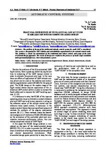
Figure 12. Unbalance response with automatic balancing and without active disk.
300
228 Advances on Analysis and Control of Vibrations – Theory and Applications
6. Conclusions The active vibration control of rotor-bearing systems using active disks for actively balancing a rotor is addressed. This approach consists of locating a balancing mass at a suitable position. Since this active control scheme requires information of the eccentricity, a novel algebraic identification approach is proposed for the on-line estimation of the eccentricity parameters. This approach is quite promising, in the sense that from a theoretical point of view, the algebraic identification is practically instantaneous and robust with respect to parameter uncertainty, frequency variations, small measurement errors and noise. Thus the algebraic identification is combined with two control schemes to place the balancing mass in the correct position to cancel the unbalance of the rotor. A velocity control is designed to take the rotor velocity to a desired operating point over the first critical speed in order to show the vibration cancellation. The controllers were developed in the context of an off-line prespecified reference trajectory tracking problem. Numerical simulations were included to illustrate the proposed high dynamic performance of the active vibration control scheme proposed.
Author details Andrés Blanco-Ortega, Jorge Colín-Ocampo, Marco Oliver-Salazar and Gerardo Vela-Valdés Centro Nacional de Investigación y Desarrollo Tecnológico, CENIDET, México Gerardo Silva-Navarro Centro de Investigación y de Estudios Avanzados del IPN, CINVESTAV, México
Acknowledgement Research reported here was supported by grants of the Dirección General de Educación Superior Tecnológica, DGEST through PROMEP under Project "Vibration control of rotating machinery".
7. References Beltrán F.; Silva, G.; Sira, H. and Quezada, J. (2005). Active vibration control using on-line algebraic identification of harmonic vibrations, Proceedings of American Control Conference, pp. 4820 - 4825, ISBN 0-7803-9099-7, Portland, Oregon, USA, June 8-10, 2005. Beltrán, F.; Sira, H. and Silva, G. (2006). Adaptive-like Active Vibration Suppression for a Nonlinear Mechanical System Using On-Line Algebraic Identification, Proceedings. of the Thirteenth International Congress on Sound and Vibration, Vienna, Austria, July 2-6, 2006. Beltrán F.; Silva, G.; Sira, H. and Blanco, A. (2010). Active Vibration Control Using On-line Algebraic Identification and Sliding Modes. Computación y Sistemas. Vol. 13, No. 3, pp 313-330. ISSN 1405-5546.
Automatic Balancing of Rotor-Bearing Systems 229
Blanco, A.; Silva, G. and Gómez, J. C. (2003). Dynamic Stiffness Control and Acceleration Scheduling for the Active Balancing Control of a Jeffcott-Like Rotor System, Proceedings of The tenth International Congress on Sound and Vibration, pp. 227-234, Stockholm, Sweden, July 7-10, 2003. Blanco, A.; Beltran, F. and Silva, G. (2007). On Line Algebraic Identification of Eccentricity in Active Vibration Control of Rotor Bearing Systems, 4th International Conference on Electrical and Electronics Engineering, pp. 253 - 256, ISBN 978-1-4244-1166-5, México, Sept. 5-7, 2007. Blanco, A.; Beltrán, F. and Silva, G. (2008). Active Disk for Automatic Balancing of RotorBearing Systems. American Control Conference, ACC 2008. pp. 3023 - 3028, ISBN 978-14244-2079-7, Seattle, WA, USA, June 11-13, 2008. Blanco, A.; Beltrán, F.; Silva, G. and Oliver, M. A. (2010). Active vibration control of a rotorbearing system based on dynamic stiffness, Revista de la Facultad de Ingeniería. Universidad de Antioquia. No. 55, pp. 125-133. ISSN. 0120-6230. Blanco, A.; Beltrán, F.; Silva, G. and Méndez, H. (2010). Control de Vibraciones en Sistemas Rotatorios, Revista Iberoamericana de Automática e Informática Industrial. Vol. 7, No. 4, (Octubre 2010.) pp. 36-43, ISSN 1697-7912. Carmignani, C.; Forte, P. and Rustighi, E. (2001). Active Control of Rotors by Means of Piezoelectric Actuators, Proceedings of Design Engineering Technical Conference and Computers and Information in Engineering Conference, p.757-764, ISBN 0791835413, Vol. 6, Pittsburgh, Pennsylvania, USA, September 9-12, 2001. Chong-Won, L. (2006). Mechatronics in Rotating Machinery. 7th IFToMM-Conference on Rotor Dynamics, pp. 25-28, Vienna, Austria, September, 2006. Dimarogonas, A. (1996). Vibration for Engineers. Prentice Hall, ISBN 978-0134562292, 1996. Dyer,, S. W.; Ni, J.; Shi, J. and Shin, K. (2002). Robust Optimal Influence-Coefficient Control of Multiple-Plane Active Rotor Balancing Systems, Journal of Dynamic Systems, Measuremente, and Control, pp. 41-46. ISSN 0022-0434, Vol. 124. El-Shafei, A. (2000). Active Control Algorithms for the Control of Rotor Vibrations Using HSFDS. Proc. of ASME TURBOEXPO 2000, Munich Germany. Fliess, M. and Sira-Ramírez, H. (2003) An algebraic framework for linear identification, ESAIM: Control, Optimization and Calculus of Variations, pp. 151-168, Vol. 9, 2003. Green K, Champneys A.R., Friswell M.I. y Muñoz (2008) A.M.Investigation of a multi-ball, automatic dynamic balancing mechanism for eccentric rotors. Royal Society Publishing, pp. 705-728, Vol. 366, No. 1866. Guozhi, Y., Fah, Y.F., Guang, C., Guang, M., Tong, F. and yang, Q., Electro-Rheological Multi-layer Squeeze Film Damper and its Application to Vibration Control of Rotor System, Journal of Vibration and Acoustics, pp. 7-11, Vol. 122, No. 1, 2000. Hathout, J. P and El-Shafei, A. (1997). PI Control of HSFDs for Active Control of RotorBearing Systems, Journal of Engineering for Gas Turbines and Power, pp. 658-667, ISSN 0742-4795, Vol. 119, No. 3. Hredzak, B. and Guo, G. (2006). Adjustable Balancer With Electromagnetic Release of Balancing Members. IEEE Transactions on Magnetics, pp. 1591-1596, Vol. 42, No. 5.
230 Advances on Analysis and Control of Vibrations – Theory and Applications
Krodkiewski, J. M. and Sun L. (1998). Modelling of Multi-Bearing Rotor Systems Incorporating an Active Journal Bearing, 215-229, Vol. 10, No. 2. Lee, J. H.; Allaire, P. E.; Tao, G. and Zhang, X. (2001). Integral Sliding-Mode Control of a Magnetically Suspended Balance Beam: Analisys, Simulation, and Experiment, Transactions on Mechatronics, pp. 338-346, Vol. 6, No. 3. Ljung, L. (1987). Systems Identification: Theory for the User. Englewood Cliffs, Prentice-Hall. Palazzolo, A. B. ; Jagannathan, S.; Kaskaf, A. F.; Monatgue, G. T. and Kiraly, L.J. (1993). Hybrid Active Vibration Control of Rotorbearing Systems Using Piezoelectric Actuators, Journal of Vibration and Acoustics, pp. 111-119, Vol. 115, No. 1. Sagara, S. and Zhao, Z. Y. (1989). Recursive identification of transfer function matrix in continuous systems via linear integral filter, International Journal of Control, pp. 457-477, Vol. 50, No. 2. Sagara, S. and Zhao, Z. Y. (1990). Numerical integration approach to on-line identification of continuous systems, Automatica, pp. 63-74. Vol. 26, No. 1, 1990 Sandler, B.Z. (1999). Robotics: designing the mechanism for automated machinery. San Diego, CA: Academic Press. Sheu, G.J., Yang, S.M. and Yang, C.D. (1997). Design of Experiments for the Controller of Rotor Systems With a Magnetic Bearing, Journal of Vibration and Acoustics, pp. , Vol. 119, No. 2, 1997. Sira, H., Márquez, R., Rivas, F. and Llanes, O. (2005) Control de sistemas no lineales: Linealización aproximada, estendida, exacta. Editorial pearson. Serie Automática, Robótica. Soderstrom, T. and Stoica, P. (1989). System Identification. New York: Prentice-Hall. Sun, L.; Krodkiewski, J. and Cen, Y. (1997). Control Law Synthesis for Self-Tuning Adaptive Control of Forced Vibration in Rotor Systems. 2nd International Symposium MV2 on Active Control in Mechanical Engineering, S9-25-37. Lyon, France. Thearle, E.L. (1932). A New Type of Dynamic Balancing Machine, ASME Journal of Applied Mechanics, pp. 131-141, No. 54. Vance, J.M. (1988). Rotordynamics of Turbomachinery. New York: John Wiley and Sons Inc. Zhou, S. and Shi, J. (2001). Active Balancing and Vibration Control of Rotating Machinery: a survey, The Shock and Vibration Digest, pp. 361-371, Vol. 33, No. 4, 2001. Zhou, S. and Shi, J. (2002). Optimal one-plane active balancing of a rigid rotor during acceleration, Journal of Sound and Vibration, pp. 196-205, ISSN 0022-460X, Vol. 249, No. 1, 2002.