As pen-based input devices have become more common, sketch recognition systems are being .... Quill: a gesture design tool for pen-based user interfaces.
Automatically Generating Sketch Interfaces from Shape Descriptions
Tracy Hammond HAMMOND @ CSAIL . MIT. EDU MIT Computer Science and Artificial Intelligence Laboratory, 32 Vassar Street, Cambridge MA, 02139 USA
1. Introduction As pen-based input devices have become more common, sketch recognition systems are being developed for many hand-drawn diagrammatic domains such as mechanical engineering, GUI design, course of action diagrams, and many others. These sketch interfaces 1) allow for more natural interaction than a traditional mouse and palette tool by allowing users to hand-sketch the diagram, 2) can automatically connect to a CAD system preventing the designer from having to enter the same information twice, 3) can offer realtime design advice from CAD systems, 4) allow more powerful editing since the shape is recognized as a whole, 5) provide diagram beautification to remove mess and clutter, 6) use display as a trigger to inform the user that the shapes have been correctly recognized. However, sketch recognition systems can be quite time consuming to build if they are to handle the intricacies of each domain. Also we would prefer that the builder of a sketch recognition system be an expert in the domain rather than an expert in sketch recognition at a signal level. Rather than build each recognition system separately, our group has been working on a multi-domain recognition system that can be customized for each domain. To build a sketch recognition system for a new domain, a developer would need only write a domain description which describes how shapes are drawn, displayed and edited in the domain, removing the need for sketch recognition expertise. This domain description would then be automatically translated into shape recognizers, editing recognizers, and shape exhibitors for use with the customizable base domain independent recognition creating a domain specific sketch interface that recognizes the shapes in the domain, displaying them and allowing them to be edited as specified in the description. The inspiration for such a framework stems from work in speech recognition, which has been using this approach with some success. This work describes an implemented prototype system that proves that such a framework is possible; that we can automatically generate a sketch interface for a domain from only a domain description. This work also serves to show that LADDER (Hammond & Davis, 2003) is an acceptable language for describing sketch interfaces and enables us to
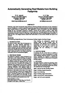
describe everything necessary to automatically generate a sketch interface. To accomplish our goal, we have built 1) LADDER , a symbolic language to describe how shapes are drawn, displayed, and edited in a domain, 2) a base customizable multi-domain recognition system, and 3) a code generator (Hammond & Davis, 2004) that parses a LADDER domain description and generates Java and Jess code to be used by the base customizable recognition system so that it can recognize, display and edit domain shapes. Figure 1 shows how all three parts of the system fit together.
2. LADDER LADDER allows interface designers to describe how shapes in a domain are drawn, displayed, and edited. An example arrow description is shown on the left-hand side of Figure 1. The domain description is transformed into shape recognizers (components and constraints), exhibitors (display section), and editors (editing) which are used in conjunction with a customizable recognition system to create a domain sketch interface. Before creating the language, we performed a user study where over 30 people described shapes with their natural vocabulary and with increasing levels of syntactical constraints in order to ensure an intuitive vocabulary and syntax. We chose a hierarchical symbolic shape-based language as we found it to be more intuitive to describe shapes in this manner, making descriptions easier to create, understand, and correct. We also noticed that not only are shape-based geometrical properties more intuitive (since shape is the salient feature used in human recognition) than feature-based properties such as those used by (Rubine, 1991; Long, 2001), but since the features (and thus recognition) are not based on drawing style, sketchers are able to draw as they do naturally, with no constraints on stroke number, order, or direction. Display and editing are important parts of a sketch interface, and are different in each domain. The display gives the user feedback that an object was recognized and beautification can be used to remove the diagram of clutter. Because the objects are recognized we can define more powerful and intuitive editing gestures, consisting of a trigger
Figure 1. System Framework
and action, for each shape. For instance, we may choose a link to be able to be dragged by its head an tail in rubberband fashion, but a wheel to be moved as a whole no matter where you drag from within the wheel’s bounding box. LADDER is the first language that not only talks about how shapes are to be recognized, but also talks about how shapes are displayed and edited.
3. Customizable Base Multi-Domain Recognition System The customizable base recognition system is shown on the right side of Figure 1. Before the higher level recognizers, exhibitors, and editors are automatically generated, the recognition system contains domain independent modules for recognizing, exhibiting, and editing all of the primitive shapes defined in LADDER. The domain independent modules of the recognition system are the shaded boxes without their inner white domain modules. Recognition is a series of bottom up opportunistic data driven triggers where the recognized shapes in the drawing represent the facts about the world. When a stroke is drawn, the system checks if it is an editing gesture, if not it is assumed to be a drawing stroke, and domain independent recognizers preprocess the stroke into some combina-
tion of primitive shapes (Ellipse, Line, Curve, Arc, Point) using techniques by (Sezgin, 2001). It is possible that more than one interpretation is possible, in which case we choose both interpretations giving them the same unique identifier so we know they come from a single stroke. Higher level recognition is then performed by the Jess rule based system. Jess first performs higher level clean up on the shapes, such as merging lines together. Jess then tries to form higher level shapes based on domain shape rules automatically generated during the code generation process by searching through all possible combination of subshapes and testing the constraints between them. When choosing between competing higher level shapes we use Okhams rule, choosing the higher level shape that accounts for more of the underlying data. If two choices are equivalent, we choose the shape created first, assuming that users prefer their shapes to remain constant on the screen. We have also implemented a greedy algorithm that removes lower level shapes from general processing to improve efficiency and to ensure that the application continues to perform in real time.
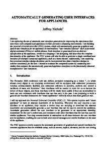
Figure 2. Variety of shapes and domains described and auto-generated.
4. Code Generation The components and constraints sections of a shape description are automatically translated into a Jess rule defining how to recognize that shape. The Jess rule created first searches for the appropriate combination of subshapes, and then tests the constraints between them. We have made the customizable base recognition system as complete as possible, including hand-coding each of the constraints within it, to keep the translation process simple. If a shape consists of a variable number of components such as a polyline (as opposed to an arrow which is composed of a fixed -3- number of components), the shape description is translated into two Jess rules, one recognizing the base case (a polyline composed of 2 lines) and the other recognizing the recursive case (a polyline composed of a line and a polyline). A shape exhibitor is automatically generated as a Java paint method for the shape, which calls functions in the base recognition system defined to work for any shape. A shape can be displayed by one or more of the following: its original strokes, its best-fit primitives, its best-fit primitives with the constraints solved, a collection of Java swing shapes, a bitmap image. A shape editor is automatically generated defining which triggers are turned on for the shape or its subshapes. If the trigger is turned on, then the actions to occur are then defined in an automatically generated edit method. All of the triggers and actions are hard-coded in the base recognition
system to work for any shapes.
5. Evaluation We have have written a LADDER domain description for the following domains: UML class diagrams, mechanical engineering, finite state machines, flowcharts, and a simplified version of course of action diagrams (Figure 2. Using the system presented in this paper, the descriptions have been automatically translated into a sketch interface which recognizes, displays, and allows editing in realtime as specified by the domain description. These descriptions include over one hundred varying shapes, with some shapes containing text, which can be entered using handwriting recognition software provided with all tablet PCs. Figures 3 shows the unrecognized and recognized strokes from a drawing made in an automatically generated mechanical engineering, flowchart, and finite state machine sketch interfaces.
6. Future Work We would like to continue to test our system on more domains and would like to continue to improve the three sections of our framework. We are building a GUI to help debug descriptions and looking for ways to make the language more intuitive and easier to describe shapes. We are in the process of building an API to allow the designer to connect to a CAD system to build more sophisticated sketch systems. (Alvarado, 2004) is working on a multi-
Figure 3. Auto-generated mechanical engineering, flowchart, and finite state machine interfaces
domain sketch recognition system that uses probabilities and context to perform top down recognition to allow for messier sketching. We would like to integrate techniques being developed by (Sezgin, 2003) to build more efficient recognizers.
7. Contributions We have developed a framework in which users can write just a LADDER domain description, and a sketch interface for that domain will be automatically generated. We have implemented a prototype system and tested our framework by writing descriptions for several domains and automatically generating sketch interfaces for these domains. To accomplish our goal, we have created 1) LADDER, a symbolic domain description language, 2) a customizable base recognition system, which performs the domain independent parts of recognition usable for many domains, and 3) a code generator that translates a domain description into higher level domain specific recognition code to be used by the customizable base recognition system.
Acknowledgements I would like to thank Olya Veselova for her help and support in creating this document while at AAAI; I am sure she would have been happier spending more of her time in San Jose outside of the hotel room rather than helping me edit and I appreciate her time and effort. I would like to thank my advisor Randy Davis and my group members
Mike Oltmans, Jacob Eisenstein, Aaron Adler, Metin Sezgin, Christine Alvarado, and Sonya Cates for all of their help in hashing out the ideas presented in this paper. I appreciate the work of Vineet Sinha for organizing the SOW conference and the program members for all of their wonderful comments on the paper. This work is supported in part by the MIT/Microsoft iCampus initiative and in part by MIT’s Project Oxygen.
References Alvarado, C. (2004). Multi-domain sketch understanding. Doctoral dissertation, Massachusetts Institute of Technology. To be published, August 2004. Hammond, T., & Davis, R. (2003). LADDER: A language to describe drawing, display, and editing in sketch recognition. Proceedings of the 2003 Internaltional Joint Conference on Artificial Intelligence (IJCAI). Hammond, T., & Davis, R. (2004). Automatically transforming symbolic shape descriptions for use in sketch recognition. Proceedings of the Nineteenth National Conference on Artificial Intelligence (AAAI-04). Long, A. C. (2001). Quill: a gesture design tool for pen-based user interfaces. Eecs department, computer science division, U.C. Berkeley, Berkeley, California. Rubine, D. (1991). Specifying gestures by example. Computer Graphics (pp. 329–337). Sezgin, T. M. (2001). Feature point detection and curve approximation for early processing in sketch recognition. Master’s thesis, Massachusetts Institute of Technology. Sezgin, T. M. (2003). Recognition efficiency issues for freehand sketches. Proceedings of the 3nd Annual MIT Student Oxygen Workshop.